The 8N model is a well-known piece of equipment that has stood the test of time. When working with this machine, it is crucial to have a clear overview of its internal and external components. This section aims to provide a detailed look at the various elements that make up the model, helping you navigate through its features efficiently.
To maintain optimal performance, it’s essential to familiarize yourself with the arrangement of key elements within the system. This overview will guide you through the model’s layout, ensuring that you can identify specific areas of interest with ease and confidence.
Whether you’re an expert or just getting started, having a clear understanding of the 8N’s configuration can greatly enhance your ability to manage and maintain it. Let’s explore the essential areas and learn how each one contributes to the overall functionality of this iconic model.
Overview of 8N Tractor Components
The 8N tractor is built from various interconnected elements that work together to ensure reliable performance in the field. Understanding these structural elements is essential for maintaining optimal functionality and ensuring the machine operates at its full potential. Below is a breakdown of the major sections that make up the tractor, each contributing to specific operational tasks.
Engine and Transmission
The engine serves as the driving force of the tractor, providing the necessary power to perform tasks such as plowing and towing. Connected to the engine is the transmission system, which regulates the tractor’s speed and movement, ensuring smooth transitions between different gears and terrain conditions.
Hydraulics and Steering
The hydraulic system allows for controlled lifting and lowering of equipment attached to the tractor, making it more versatile for a variety of agricultural activities. The steering mechanism is designed for precise control, allowing the operator to maneuver the
Key Sections in the 8N Parts Layout
The layout of the 8N equipment is organized into distinct categories that ensure efficient maintenance
Understanding the Engine Assembly Diagram
When examining the core components of the engine structure, it is essential to recognize the importance of each element and its role in the overall operation. The layout presents a clear view of how various mechanical elements come together to ensure efficient functioning. By understanding the relationships between these components, maintenance and troubleshooting become much more straightforward.
Main Components Overview
- The core block, which houses the primary mechanisms and provides a solid foundation for all moving parts.
- Internal mechanisms that work together to transform energy into motion, ensuring consistent performance.
- The fluid systems that ensure proper lubrication and cooling, which are crucial for preventing overheating and wear.
Key Connections
- First, look at how the pistons interact
Transmission System: Parts Breakdown

The transmission system is crucial for transferring power from the engine to the wheels, ensuring smooth and efficient vehicle operation. Understanding its structure allows for easier maintenance and repairs, as each component plays a vital role in the overall function. Below, we’ll explore the key elements that make up this essential system.
Main Components
- Gearbox: Responsible for adjusting the torque and speed of the vehicle, the gearbox shifts gears to match driving conditions.
- Clutch Assembly: Engages and disengages power transmission, allowing for smooth gear changes without damaging the system.
- Driveshaft: Connects the transmission to the differential, transferring rotational power from the engine to the wheels.
Additional Elements

- Exploring the Electrical System Layout
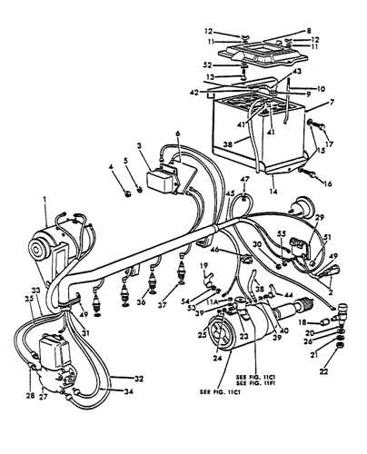
The electrical framework of this model encompasses a network of key connections and components that ensure its efficient operation. Understanding the arrangement of these elements is crucial for troubleshooting and maintenance. This section delves into the various elements that make up the system and how they interact with each other.
- Power Source: The central component responsible for supplying energy throughout the vehicle.
- Wiring Configuration: A network of cables that ensures the smooth transmission of electrical signals to various elements.
- Connection Points: Key junctions where different parts of the system come together to maintain consistent functionality.
- Control Mechanisms: Switches and relays that help regulate the flow of electricity, enabling smooth operation.
By familiarizing yourself with the overall layout, you can better understand how each part functions together to keep the electrical system running smoothly and reliably.
Steering Mechanism: Parts and Connections
The steering system is crucial for ensuring precise navigation and control of a vehicle. It encompasses various components that work together seamlessly to enable smooth movement and responsiveness. Understanding the individual elements and their interrelations is essential for effective maintenance and troubleshooting.
Key elements involved in the steering mechanism include:
- Steering wheel
- Steering column
- Gearbox
- Connecting rods
- Linkages
- Knuckle joints
Each element plays a specific role in the overall functionality:
- Steering Wheel: The driver’s interface for initiating directional changes.
- Steering Column: Connects the steering wheel to the gearbox, transmitting movement.
- Gearbox: Transforms the rotational motion from the steering column into lateral movement.
- Connecting Rods: Link the gearbox to other components, ensuring force transmission.
- Linkages: Assist in transferring motion and stabilizing the system.
- Knuckle Joints: Allow for pivoting and movement of the wheels during steering.
Understanding these elements and their functions allows for better diagnosis of issues that may arise within the steering system, ensuring the vehicle remains safe and responsive.
Hydraulics System Overview for the 8N
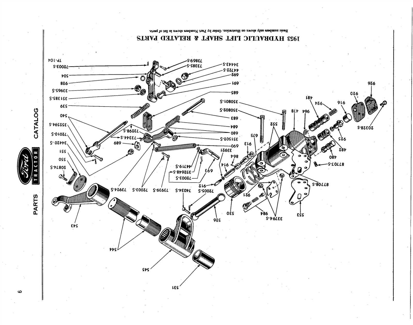
The hydraulic system in the 8N model plays a crucial role in enhancing the overall functionality and efficiency of the equipment. This system utilizes fluid power to facilitate various operations, ensuring that tasks are performed smoothly and effectively.
At its core, the hydraulic mechanism comprises several key components that work in unison. These elements enable the transfer of force and motion through fluid movement, allowing the user to accomplish demanding tasks with ease. The system’s design promotes optimal performance while minimizing wear and tear, ensuring longevity and reliability.
Understanding the workings of the hydraulic system can significantly enhance user experience. By familiarizing oneself with its operation, one can effectively troubleshoot common issues, perform routine maintenance, and optimize the equipment’s capabilities. This knowledge empowers users to harness the full potential of the 8N model for various agricultural and industrial applications.
Brake Components and Their Placement
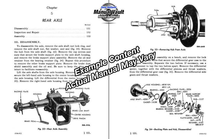
Understanding the elements involved in the braking system is essential for optimal vehicle performance. Each component plays a crucial role in ensuring safe and efficient stopping power. Proper arrangement and functioning of these elements are vital for maintaining control and stability while driving.
- Brake Pedal: The interface between the driver and the braking system, this component activates the brakes when pressure is applied.
- Master Cylinder: This device converts the force exerted on the brake pedal into hydraulic pressure, allowing the system to function effectively.
- Brake Lines: These conduits transport hydraulic fluid from the master cylinder to the brake calipers or wheel cylinders.
- Brake Calipers: These components house the brake pads and apply pressure to the brake discs or drums to create friction and slow the vehicle.
- Brake Pads: These friction material pieces press against the rotor to generate the necessary stopping force.
- Brake Rotors: Mounted on the wheel hubs, they provide a surface for the brake pads to clamp onto, converting kinetic energy into heat.
- Wheel Cylinders: In drum brake systems, these elements push the brake shoes against the drum to create friction and reduce speed.
- Brake Shoes: Found in drum brakes, they expand against the inner surface of the drum to facilitate deceleration.
Each of these components is strategically located within the braking system to ensure effective operation. Regular inspection and maintenance of these elements are recommended to prevent any performance issues and to promote safe driving conditions.
Fuel System Diagram for the 8N Tractor
The fuel mechanism in the 8N Tractor is essential for efficient operation, ensuring that the engine receives the proper mixture needed for optimal performance. Understanding how this system functions can greatly assist operators in troubleshooting and maintenance tasks.
Below is a simplified overview of the components involved in the fuel delivery process, showcasing their arrangement and interaction:
Component Description Fuel Tank Stores fuel and feeds it into the system. Fuel Filter Removes impurities and debris from the fuel. Fuel Pump Transfers fuel from the tank to the engine. Carburetor Mixes fuel with air for combustion. Fuel Lines Transport fuel between components. By familiarizing yourself with these elements, you can ensure that the fuel system operates smoothly, leading to enhanced performance and longevity of the 8N Tractor.
Cooling System Parts and Arrangement
The cooling system plays a crucial role in maintaining optimal operating temperatures within a machinery unit. Its efficient configuration ensures that heat generated during operation is effectively managed, preventing overheating and potential damage. Understanding the components and their layout is essential for proper maintenance and troubleshooting.
Key components involved in the cooling system include:
- Radiator
- Thermostat
- Water pump
- Cooling fan
- Hoses
These elements work in concert to regulate temperature. The radiator serves as the primary heat exchanger, dissipating heat from the coolant. The thermostat regulates the flow of coolant based on temperature readings, while the water pump circulates the coolant throughout the system. The cooling fan assists in enhancing airflow, particularly during low-speed operation or idle conditions.
The arrangement of these components is designed to maximize efficiency. Typically, the radiator is positioned at the front of the engine bay, allowing for optimal airflow. Hoses connect the radiator to the engine block, facilitating the movement of coolant. Each element’s location is strategically determined to ensure that the cooling system functions effectively, contributing to the overall performance and longevity of the equipment.
Maintenance Tips Using the Parts Diagram
Effective upkeep of machinery involves understanding its components and their interrelations. A visual representation of these elements can greatly assist in identifying areas requiring attention and facilitating repairs. By following a few simple guidelines, operators can enhance the longevity and efficiency of their equipment.
Regular Inspections: Conduct frequent checks on the various elements of your machinery. This practice helps in spotting wear and tear early on, allowing for timely interventions before issues escalate. Pay attention to signs of damage or unusual noises that may indicate a malfunction.
Consultation of Visual Aids: Utilize available visual guides to familiarize yourself with the arrangement and function of each component. These resources can provide insights into how parts work together, making troubleshooting more intuitive.
Replacement and Upgrades: When identifying worn components, refer to the visual guide for accurate replacement information. Upgrading certain elements can improve overall performance and energy efficiency, thus reducing operational costs.
Documentation: Keep a maintenance log to track inspections, repairs, and replacements. This record serves as a valuable reference for future maintenance and helps in understanding the equipment’s history, which can inform decision-making.
By applying these strategies and utilizing visual references, operators can ensure their machinery remains in optimal condition, ultimately leading to improved performance and reduced downtime.