In the realm of mechanical and electrical devices, understanding how various elements interconnect is key to ensuring efficient upkeep and repairs. Each unit within a machine has specific elements that contribute to its overall functionality. Recognizing these components and their placement allows for more efficient troubleshooting and repair strategies, saving both time and resources.
Detailed visualization of the internal structure of a device offers a clear overview of its elements. This layout not only aids in identifying the location of each element but also helps in better comprehension of their roles. For those involved in the repair or maintenance process, such clarity is invaluable for ensuring that replacements and repairs are carried out smoothly and correctly.
Whether dealing with regular maintenance or unexpected malfunctions, having a detailed understanding of the unit’s layout is critical. By studying the arrangement and connections between various internal elements, it becomes easier to identify potential issues and take appropriate corrective actions. This process helps maintain the device’s optimal performance and prolong its operational life.
970l48022a0 Parts Breakdown
The following section provides a detailed overview of the individual components and their arrangement within the system. Each element plays a crucial role in ensuring proper functionality, and understanding the structure helps in effective maintenance and repair.
- Component A – Key for overall operation, often positioned at the core.
- Element B – Integral to the system’s mechanical functions, typically located near the main assembly.
- Module C – Supports electrical processes, connecting various internal sections.
- Section D – Ensures stability and balance within the framework, securing multiple layers.
- Unit E – Frequently acts as a protective casing or cover, safeguarding sensitive areas.
By familiarizing yourself with these elements, it becomes easier to identify potential issues and conduct necessary repairs with greater precision.
Key Components Overview
The following section provides a detailed description of the essential elements and structures that form the core of the system. Each component plays a significant role in ensuring the smooth operation and efficiency of the entire unit. Understanding these elements is crucial for maintaining optimal performance and diagnosing potential issues.
Main Structural Units
The primary units are responsible for the overall stability and functionality of the system. These include foundational elements that hold the entire structure together, as well as those that facilitate movement and control. Their robust design ensures long-term durability and reliability under varying conditions.
Operational Mechanisms
The operational mechanisms consist of intricate systems that regulate the flow of processes and ensure precise coordination. These mechanisms are finely tuned to provide seamless interaction between different sections, enhancing the efficiency of the system. Proper care and regular maintenance are necessary to avoid disruptions and ensure continued functionality.
Exploded View of Main Assembly
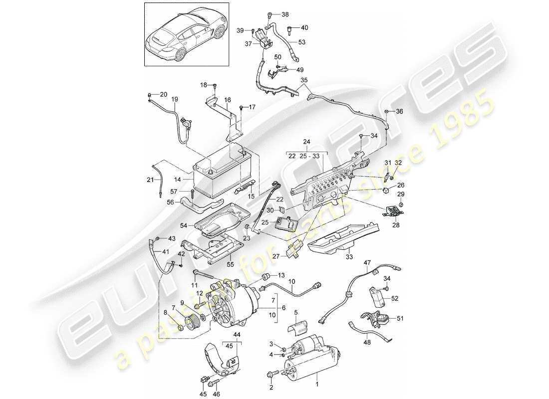
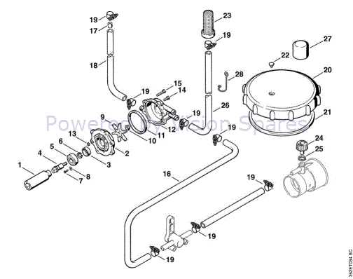
The breakdown of the central structure provides a clear and detailed visualization of each element, showing how individual components are arranged and how they fit together. This view simplifies the understanding of the entire unit, allowing for a comprehensive look at how all the sections interact.
Main Components Overview
The visual breakdown highlights key sections, showing each element in its proper position. From the core framework to smaller connecting parts, the arrangement ensures a logical flow for anyone examining the assembly.
Detailed Layout Explanation

This exploded representation offers an in-depth look at every critical part, emphasizing their placement and function. The expanded layout is designed to guide you through the structure step-by-step, making it easier to understand the overall construction.
Detailed Sectional Breakdown
The sectional breakdown provides an in-depth look at the components and their arrangement within the mechanism. This structure enables a clear understanding of how each element is interconnected and contributes to the overall functionality. Through a step-by-step approach, the layout of individual units is explained, offering clarity for maintenance and assembly.
Each segment within the system is carefully analyzed, highlighting its importance and relationship to neighboring elements. Special attention is given to the sequence in which the items are organized, ensuring a coherent flow of information for those needing to explore the internal workings of the device.
Understanding the configuration of these sections is essential for efficient troubleshooting and repair, as it allows for precise identification of key areas within the unit. The breakdown offers an accessible guide to follow during both routine checks and more detailed assessments.
Parts Identification Guide
Understanding the various components of your device is essential for efficient maintenance and repair. This guide aims to help you recognize and identify different sections, making it easier to manage upkeep or replacements when necessary.
| Component | Description |
|---|---|
| Main Assembly | The core structure that houses and connects all other elements. |
| Control Unit | Manages the overall functionality and settings, ensuring proper operation. |
| Connector Elements | Links different sections together, facilitating seamless communication between them. |
| Power Supply Section | Provides necessary energy to drive the system efficiently. |
| Fastening Elements | Securely holds the components in place, maintaining stability during operation. |
Material Composition and Specifications
This section explores the various materials and specifications used in the assembly, highlighting their significance in functionality and durability. Understanding the composition is essential for comprehending the overall performance and longevity of the components involved.
Key Materials
The components are primarily crafted from high-quality metals and polymers, ensuring a robust and reliable structure. These materials are selected for their excellent resistance to wear and environmental factors, which contributes to the longevity of the unit. For instance, the use of corrosion-resistant alloys helps maintain integrity under adverse conditions.
Specifications Overview
Specifications play a crucial role in determining compatibility and efficiency. Key factors include dimensions, weight, and tensile strength, all of which must meet stringent industry standards. Weight specifications ensure that the components are easy to handle and install, while dimensions are critical for proper fitting within the assembly. Additionally, tensile strength measurements indicate the ability of the materials to withstand operational stresses without failure.
Replacement Procedures for Damaged Parts
Ensuring the longevity and optimal performance of any equipment often involves timely intervention when components suffer wear or damage. This section outlines the essential steps for effectively replacing these compromised elements, helping maintain functionality and safety.
Preparation for Replacement
Before initiating the replacement process, it’s crucial to gather the necessary tools and materials. Proper preparation minimizes complications and facilitates a smoother operation.
- Identify the specific component needing replacement.
- Gather appropriate tools, such as screwdrivers, pliers, or wrenches.
- Acquire the correct replacement item, ensuring compatibility.
- Review any manufacturer instructions or guidelines related to the procedure.
Step-by-Step Replacement Process
Follow these steps to successfully replace the damaged component:
- Ensure the equipment is turned off and disconnected from any power source.
- Carefully remove any coverings or access panels to reach the damaged element.
- Loosen and detach the old component using the appropriate tools.
- Install the new part, ensuring it aligns correctly with existing fixtures.
- Reassemble any panels or coverings, making sure all fasteners are secure.
- Reconnect the power source and conduct a test to confirm functionality.
Regular maintenance and prompt replacements are vital for prolonging the life of your equipment. Following these guidelines will help ensure that replacements are executed efficiently and effectively.
Critical Components Maintenance

Ensuring the optimal performance of essential elements in any machinery is vital for prolonged functionality and efficiency. Regular upkeep and monitoring not only enhance the longevity of these components but also prevent unexpected failures that could lead to costly repairs or downtime. This section will delve into effective maintenance practices tailored for key parts of the system.
Regular Inspections
Conducting frequent assessments of critical elements is fundamental in identifying wear and tear before they escalate into significant issues. Inspecting these parts for signs of damage or degradation allows for timely interventions, ensuring that any potential problems are addressed swiftly. Utilizing a systematic approach for evaluations can significantly improve the reliability of the machinery.
Lubrication and Cleaning
Proper lubrication is essential for minimizing friction and wear on moving parts, which directly impacts overall performance. It is equally important to maintain cleanliness by removing debris and contaminants that can interfere with operation. Implementing a consistent cleaning and lubrication routine will safeguard against premature component failure and ensure smooth functionality.
Connection Points and Interfaces
This section explores the various connection points and interfaces found within the specified model, highlighting their significance in ensuring optimal functionality and seamless integration with other components. Understanding these elements is essential for efficient assembly and troubleshooting, as they serve as critical pathways for data and power transfer.
Types of Connection Points
Connection points play a vital role in the interaction between different parts of the system. They can vary in form and function, facilitating electrical connections, fluid transfer, or mechanical coupling. Recognizing the types of connection points is crucial for maintaining system integrity and performance.
| Type | Description | Function |
|---|---|---|
| Electrical Connector | Points for connecting wires or cables to transmit power or signals. | Ensures electrical communication between components. |
| Fluid Port | Openings designed for the entry and exit of fluids. | Facilitates fluid movement within the system. |
| Mechanical Interface | Surfaces designed for physical connection between parts. | Provides structural support and stability. |
Significance of Interfaces
Interfaces are essential for the proper functioning of interconnected systems. They ensure compatibility between different components, allowing them to work harmoniously. Recognizing the importance of these interfaces aids in the effective operation and maintenance of the overall system.
Component Numbering and Labeling
The process of assigning identification numbers and labels to individual elements is crucial in any mechanical assembly. This systematic approach enhances clarity and aids in effective communication among technicians, engineers, and operators. A well-organized numbering system simplifies maintenance and troubleshooting efforts, ensuring that components can be easily located and replaced when necessary.
Importance of a Clear System
A clear and concise identification system serves multiple purposes:
- Facilitates quick reference during maintenance tasks.
- Reduces the risk of errors in component selection.
- Improves inventory management and tracking.
- Enhances documentation accuracy and accessibility.
Best Practices for Labeling
Implementing effective labeling involves several best practices:
- Use consistent numbering formats across all elements.
- Ensure labels are durable and resistant to environmental factors.
- Incorporate color-coding to differentiate categories or functions.
- Regularly update the labeling system to reflect changes in design or components.
By adhering to these principles, organizations can maintain a reliable framework for managing their mechanical assemblies, promoting efficiency and reducing downtime.
Compatible Parts and Substitutes

In the realm of machinery and equipment, identifying alternative components is crucial for ensuring optimal performance and longevity. Understanding which replacements can effectively serve as stand-ins for original elements allows users to maintain functionality even when original items are unavailable or costly. This section aims to highlight various alternatives that can seamlessly integrate into existing systems.
Alternative Components
When seeking substitutes, it is essential to consider options that match the specifications and compatibility requirements of the original items. Various manufacturers offer similar replacements designed to meet or exceed the performance standards of the originals. These alternatives often come at a more accessible price point, providing an economical solution without sacrificing quality.
Benefits of Using Compatible Replacements
Utilizing compatible substitutes can lead to enhanced flexibility in maintenance and repairs. Users benefit from a broader selection of components, which can expedite the procurement process. Additionally, many alternative components are designed to be interchangeable with their original counterparts, ensuring straightforward installation and operation.