| Battery |
How to Read Electrical Circuit Maps
Understanding the layout of electrical pathways is crucial for working with complex systems. These visual guides help trace the flow of energy and identify the connections between different components. Whether it’s a simple or intricate setup, knowing how to interpret the pathways can save time and prevent errors.
Identifying Key Symbols
Each electrical map uses a set of standardized symbols to represent different components. Resistors, capacitors, switches, and other elements are shown in symbolic form. Familiarizing yourself with these symbols is the first step to efficiently reading any map. Many resources provide comprehensive lists, so it’s important to have them on hand when reviewing.
Following the Flow of Energy
Another essential skill is tracking the flow of current through the network of lines. Lines on these maps show the connections between components, and by following these, you can determine how energy moves through the system. Keep in mind that some maps may include various pathways, so attention to detail is key when interpreting the full setup.
Mechanical Parts Representation in Auto Blueprints
The visual portrayal of key structural components in technical drafts plays a crucial role in understanding how various systems function together. Each item is carefully illustrated, providing a clear overview of its placement and role within the overall mechanism. These depictions offer valuable insights into how different systems interact and how they are engineered to work in harmony.
Below are some key aspects that are often highlighted when examining technical sketches:
- Connection points between different components
- Specific alignment and orientation details
- Dimensional accuracy for manufacturing and repair
- Details of fasteners and assembly methods
- Material specifications and tolerances
Each of these elements is crucial for ensuring that the machine functions efficiently and reliably over time. By understanding how these are presented in blueprints, technicians and engineers can more effectively diagnose, repair, and improve the overall design.
Decoding Engine Layout Diagrams
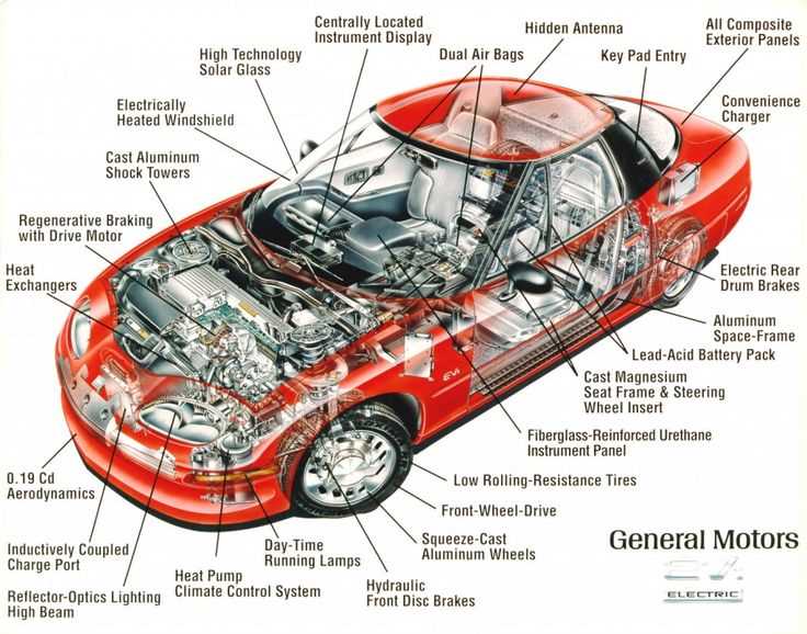
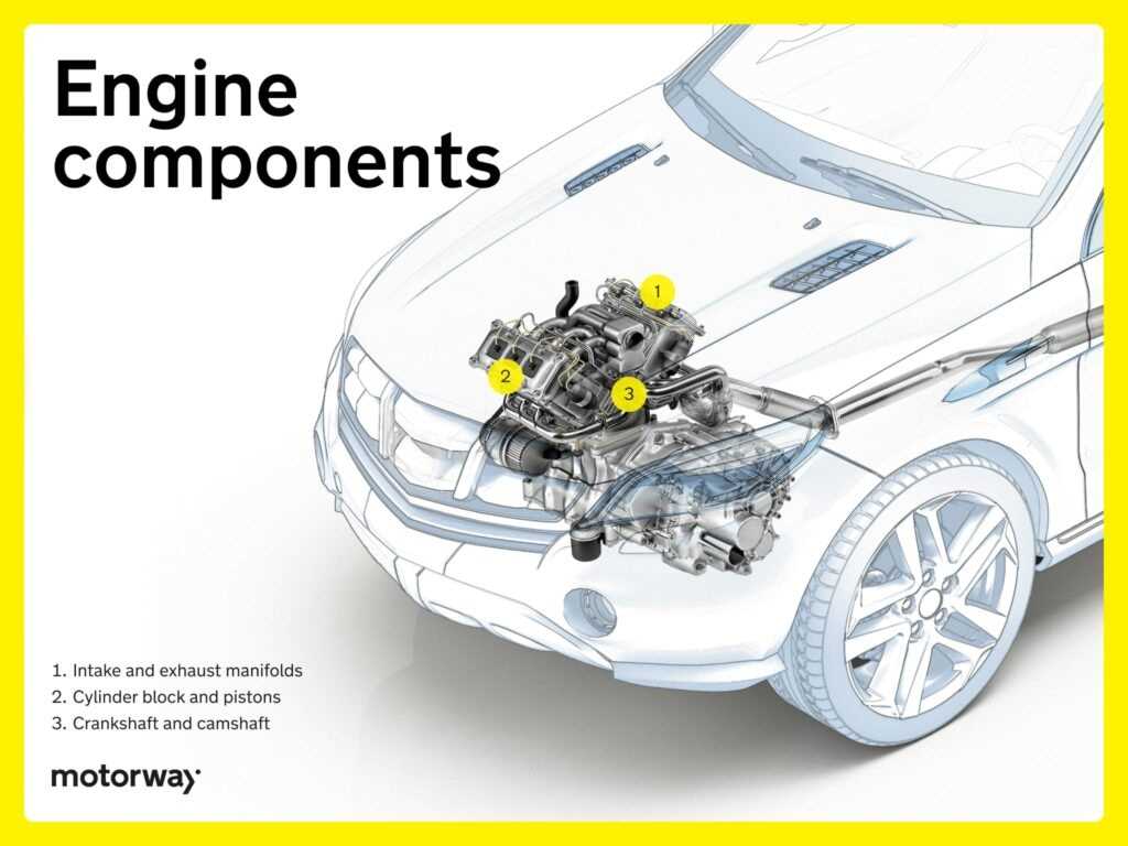
Understanding the organization of mechanical components in a motor can seem complex at first glance. The various elements are arranged in a specific order to ensure optimal performance and efficiency. Each component has a unique role, and their placement follows a structured logic that balances power distribution, cooling, and other essential functions.
By analyzing the structure, you can gain insight into how different systems interact with each other. Whether it’s fuel delivery, cooling systems, or exhaust, every piece is positioned for a reason. Learning to interpret these layouts helps you navigate and maintain these intricate systems more effectively.
Familiarity with these configurations allows for easier troubleshooting and performance enhancements. Once you grasp the core principles behind the arrangement of these systems, working with them becomes far more manageable and intuitive.
Transmission System in Vehicle Schematics
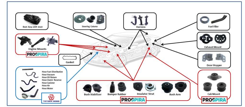
The transmission system plays a vital role in transferring power from the engine to the wheels, ensuring smooth and efficient movement. This section explores the key components involved and how they interact to regulate speed and torque distribution. Understanding this mechanism is essential for anyone looking to maintain or troubleshoot their vehicle’s operation.
Main Components and Their Functions
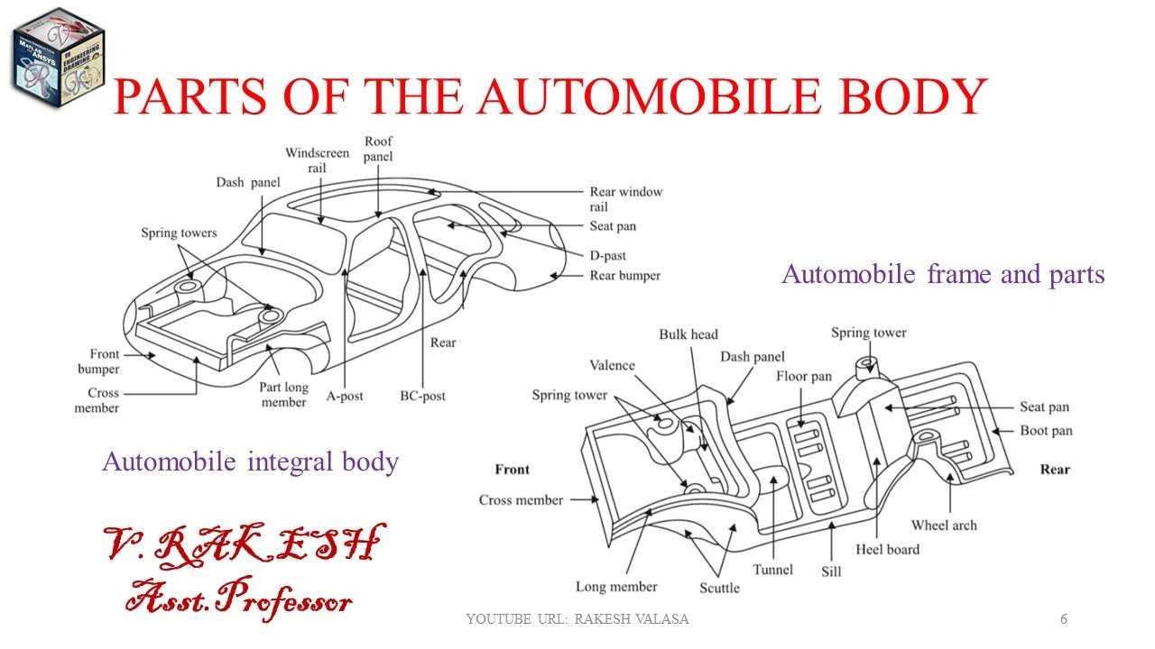
- Gearbox: Controls the speed and torque by adjusting the gear ratios based on the engine’s power.
- Clutch: Engages and disengages power flow from the engine, allowing for gear shifts and vehicle control.
- Driveshaft: Transmits rotational force from the gearbox to the wheels for movement.
Types of Transmission Systems
- Manual: Requires the driver to manually shift gears using a clutch pedal and gear stick.
- Automatic: Automatically adjusts gears based on the vehicle’s speed and load without driver input.
- Semi-Automatic: A hybrid system offering both manual and automatic control over gear shifts.
Identifying Brake Components in Auto Charts
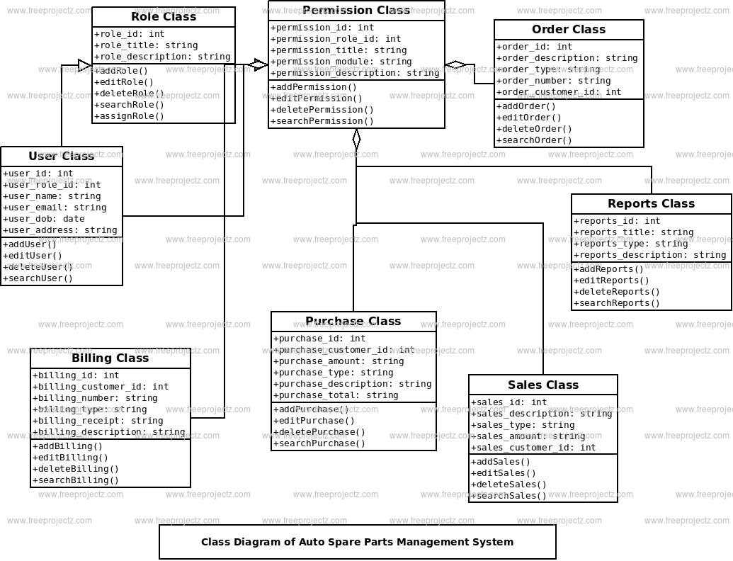
Understanding the key elements responsible for a vehicle’s braking system is essential for proper maintenance and repairs. These systems consist of various interconnected elements, each playing a critical role in ensuring safety during operation. Accurately identifying these elements in technical illustrations is crucial for mechanics and enthusiasts alike.
The primary elements often highlighted include the brake pads, which are responsible for creating friction, the rotors that interact with the pads, and the calipers, which apply pressure to the pads. Other supporting mechanisms, such as hydraulic lines and the master cylinder, also contribute to effective braking performance.
By familiarizing yourself with the positioning and function of these components, you can enhance your understanding of the overall system, making troubleshooting and repairs more efficient. Paying close attention to how these parts are illustrated will provide valuable insights into their operation and maintenance requirements.
Fuel System Representation in Car Diagrams
Understanding the fuel delivery process is essential for efficient vehicle performance. Various elements come together to ensure a smooth supply of fuel from the tank to the engine. These components, working in harmony, highlight the complexity and importance of this system. This section will provide insights into how these elements are depicted, focusing on their functional roles.
Main Components Overview
The fuel tank serves as the starting point, housing the necessary supply. From there, a pump pushes the fuel through lines, which are critical in transporting the fuel to the engine. Filters are positioned to ensure cleanliness, preventing debris from entering the engine. The injectors then deliver precise amounts of fuel to the combustion chambers, enabling optimal energy conversion.
Depiction of Flow and Control
In many representations, the flow is shown from the fuel tank through various valves and regulators. These regulators control the pressure, ensuring that the right amount of fuel reaches the engine. Understanding these connections helps identify potential issues, such as blockages or pressure drops, that can affect performance. Visuals often emphasize the connectivity between these elements to provide a clear picture of fuel flow dynamics.
Bodywork and Structural Elements in Drawings
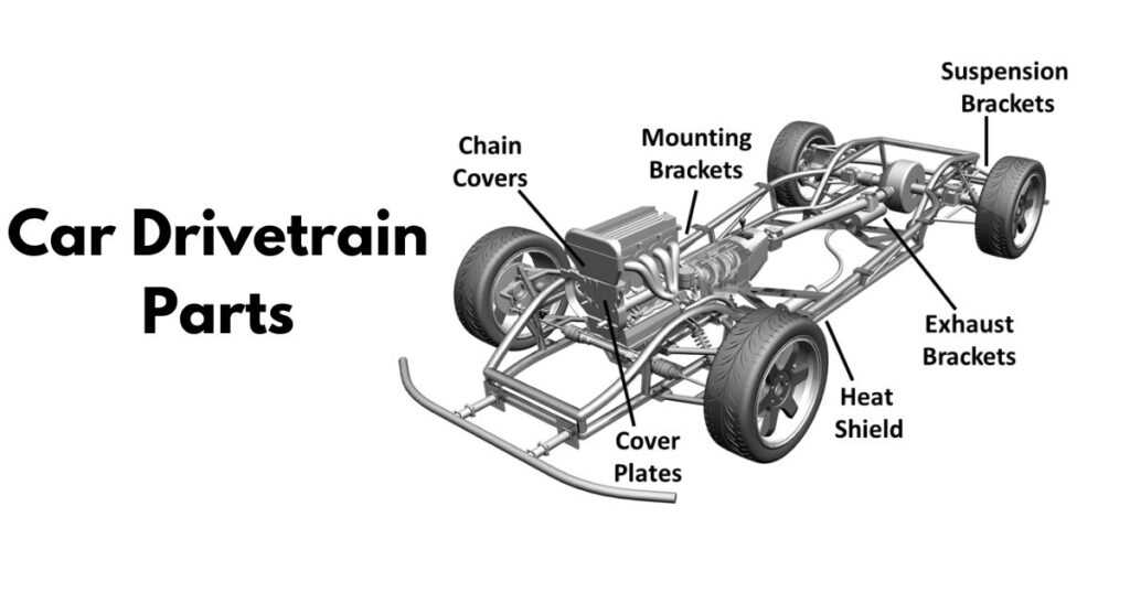
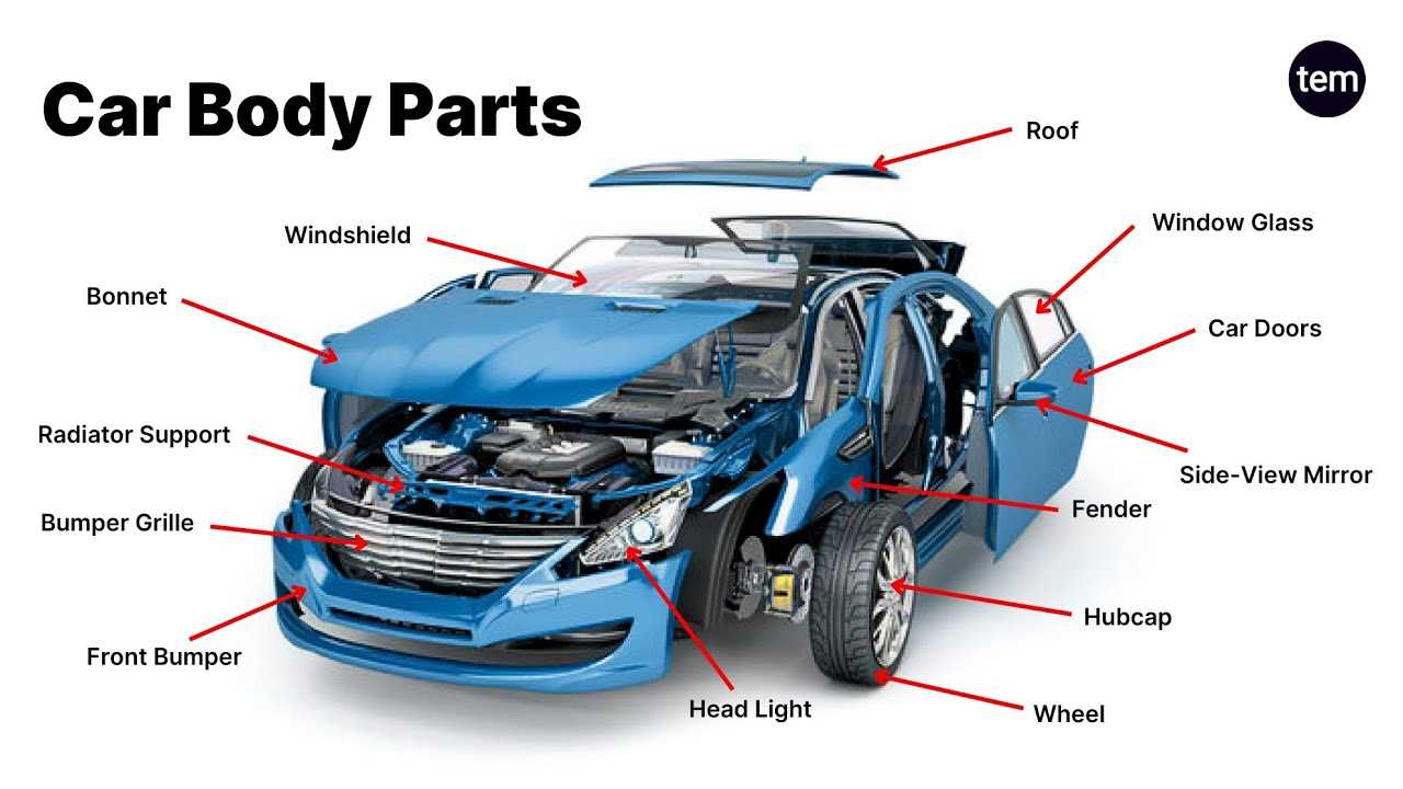
The representation of external coverings and foundational components is crucial for understanding the overall configuration of a vehicle. These illustrations serve as visual guides, highlighting the various sections that contribute to the integrity and aesthetics of the machine. The accurate depiction of these elements ensures that both designers and technicians can comprehend the intricacies involved in assembly and repair.
External Shells: The outer casings, crafted from various materials, protect the inner mechanisms while providing an appealing finish. They are essential for aerodynamics and safety, influencing the performance of the vehicle.
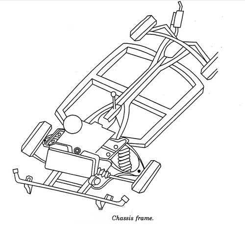
Support Framework: The structural framework provides the necessary strength and stability, supporting the entire assembly. This framework is designed to absorb impacts and distribute loads, ensuring durability and resilience during operation.
Understanding these elements in detailed representations allows for enhanced collaboration among engineers and mechanics, facilitating effective problem-solving and innovation in the design process.
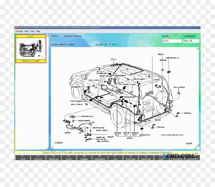
Wiring Harness Layouts in Vehicle Schematics
The configuration of wiring systems plays a crucial role in the functionality and efficiency of any vehicle’s electrical framework. Understanding the arrangement of these systems can significantly enhance troubleshooting processes and maintenance efforts.
Key Components of Wiring Arrangements
- Connectors: Junctions where wires meet, enabling communication between various systems.
- Cables: Conductors that transmit electrical signals throughout the structure.
- Ground Points: Critical locations that establish a return path for current, ensuring system stability.
- Fuse Boxes: Protective units that safeguard circuits from overloads and shorts.
Importance of Proper Layout
- Enhances the reliability of electrical systems.
- Facilitates efficient diagnostics and repairs.
- Reduces the likelihood of electrical failures.
- Promotes safer operation of all components.
Cooling System Depiction in Automotive Blueprints
The representation of thermal management structures in vehicle schematics plays a crucial role in ensuring efficient temperature regulation. These frameworks are essential for maintaining optimal operating conditions and preventing overheating, thereby safeguarding the performance and longevity of the engine. A well-designed schematic provides insights into the various components and their interconnections within the cooling apparatus.
Key Components of Thermal Management Frameworks
- Radiator: Facilitates heat exchange with the environment.
- Water Pump: Circulates coolant throughout the system.
- Thermostat: Regulates coolant flow based on temperature.
- Cooling Fans: Enhance airflow across the radiator.
- Hoses: Connect different elements, allowing for fluid movement.
Understanding the Interconnections
The synergy between components is vital for the cooling process. Each element works in concert, with coolant flowing through a closed loop, absorbing heat from the engine and dissipating it through the radiator. Understanding these interactions is essential for troubleshooting and optimizing performance.
- Inspect the coolant levels regularly.
- Ensure the radiator is free from obstructions.
- Check hoses for wear and leaks.
- Test the thermostat function periodically.
Steering Mechanism in Technical Diagrams

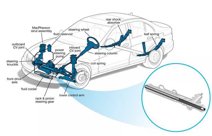
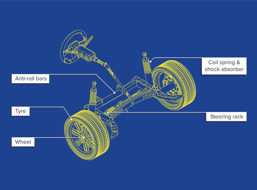
The steering system is a crucial component in any vehicle’s layout, responsible for guiding its direction and ensuring stability during operation. This section explores the intricacies of this essential mechanism, highlighting its design and functionality within schematics.
Understanding the steering mechanism involves examining various elements such as the column, gears, and linkages that facilitate control. These components work in unison to translate the driver’s input into precise movements, allowing for responsive handling and maneuverability.
In technical representations, the steering mechanism is often depicted with clear symbols and annotations that illustrate how forces are transferred throughout the system. This visual representation aids engineers and technicians in troubleshooting and optimizing performance, ensuring a safe and effective driving experience.
