Understanding the internal structure and organization of a compact excavator is essential for efficient maintenance and repair. This type of equipment is known for its reliability in a variety of demanding tasks, and having detailed knowledge of its design can significantly reduce downtime during servicing.
In this article, we will explore the layout of the machine’s key elements, providing a clear overview of how its various mechanisms work together. This knowledge is invaluable for ensuring optimal performance and longevity, helping operators and technicians alike to identify and address potential issues early.
By reviewing the arrangement of the main components, one can gain deeper insights into the efficient operation of these versatile machines. Whether you’re involved in routine upkeep or a more complex repair, having a clear understanding of the equipment’s internal setup will make your job easier and more effective.
Overview of the Bobcat 331 Component Layout
The structure of this compact machine is built to ensure efficiency and durability in various applications. Understanding the arrangement of its core elements is crucial for both maintenance and operation. By exploring the layout, one can gain insights into how the primary systems work together seamlessly.
- Engine Placement: Positioned for optimal access, allowing easy maintenance and repair tasks.
- Hydraulic System: Centrally located to provide balanced power distribution and fluid control across all functions.
- Cylinder Block: The foundation of the motor, housing crucial moving parts such as pistons and connecting rods.
- Crankshaft: Converts the linear motion of the pistons into rotational energy to power other systems.
- Camshaft: Coordinates the timing of the intake and exhaust valves to control airflow in and out of the engine.
- Timing Belt: Ensures synchronization between the crankshaft and camshaft for precise operation.
- Oil Pump: Provides lubrication to reduce friction and wear on
Detailed View of the Undercarriage Components
The undercarriage plays a crucial role in ensuring stability and smooth movement across different terrains. Understanding its components is essential for maintaining optimal performance. This section offers an overview of the essential elements that contribute to the efficient functioning of the system beneath the machine.
Component Function Tracks Provides traction and helps the machine move over rough surfaces. Sprockets Engage with the tracks to drive the movement. Rollers Support the weight of the vehicle and guide the tracks smoothly. Electrical System Layout and Connections
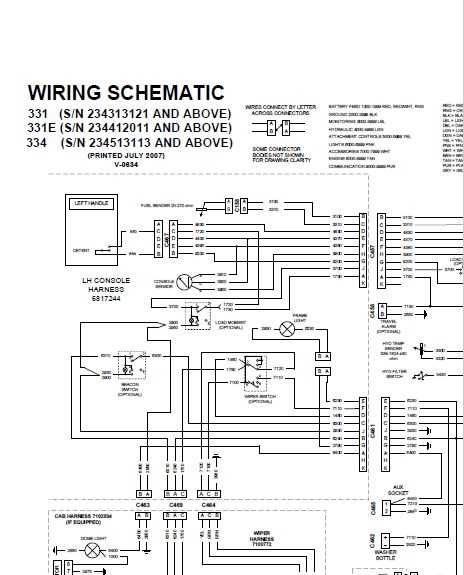
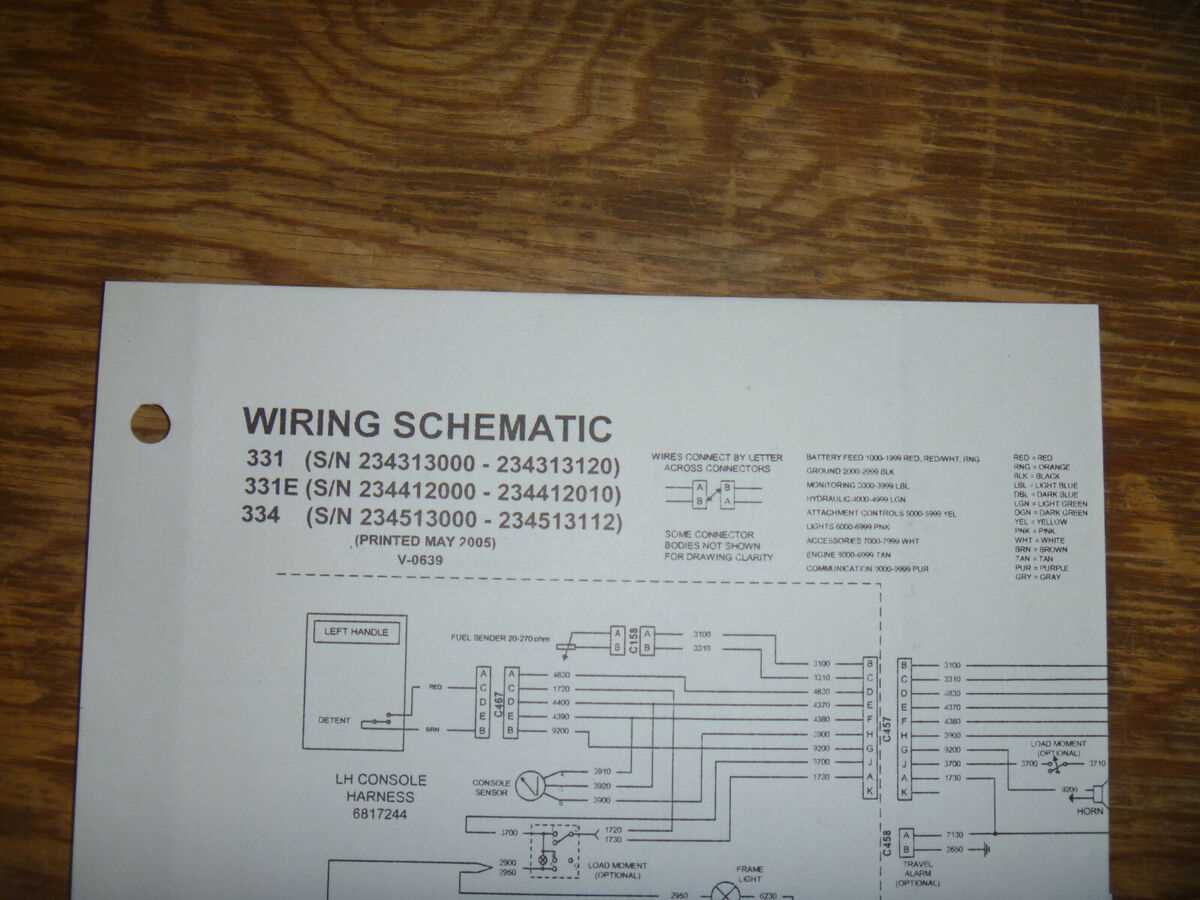
The electrical system is a crucial component, ensuring the proper functioning of all integrated features. It encompasses various circuits and connectors, designed to provide reliable power distribution and communication between different systems. Understanding the layout of these elements is essential for efficient maintenance and troubleshooting.
This section focuses on the arrangement of wiring paths and the specific connections that link power sources to operational units. By tracing the flow of electricity, one can easily identify key areas of interest, ensuring optimal performance and addressing any potential issues with the wiring network.
Additionally, the integration of connectors, switches, and relays within the system plays a vital role in controlling electrical signals. A clear grasp of these components is necessary for ensuring smooth operations and diagnosing malfunctions.
Control Mechanism Overview
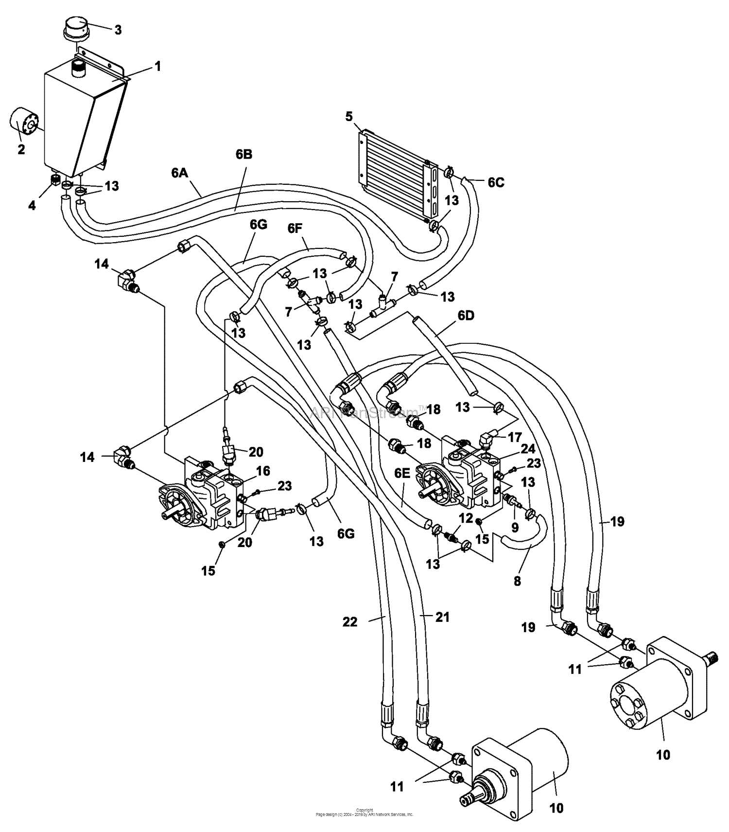
The control system in compact machinery plays a crucial role in ensuring precise operation and optimal performance. This intricate setup is designed to manage various functions, allowing operators to maneuver the equipment efficiently. Understanding the components involved in this system is essential for effective handling and maintenance.
At the heart of the control mechanism lies the interface through which the operator communicates with the machine. This includes levers, pedals, and buttons that translate user input into actionable commands. Each element is engineered for responsiveness, contributing to seamless interactions and improved operational efficiency.
Additionally, the system incorporates hydraulic and electrical components that facilitate the movement of various parts. These elements work in unison to execute tasks ranging from lifting to digging, demonstrating the importance of a well-coordinated control mechanism. Regular inspection and maintenance of these components ensure reliability and longevity of the equipment.
Track System and Tensioning Parts Explained
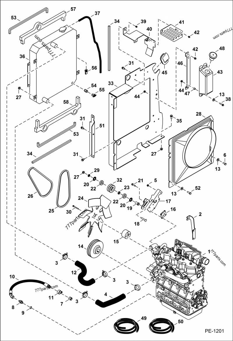
The track mechanism is a vital component of compact machinery, ensuring optimal movement across various terrains. This section delves into the essential elements that contribute to the functionality and stability of the track system, highlighting their roles and significance.
Components of the Track System
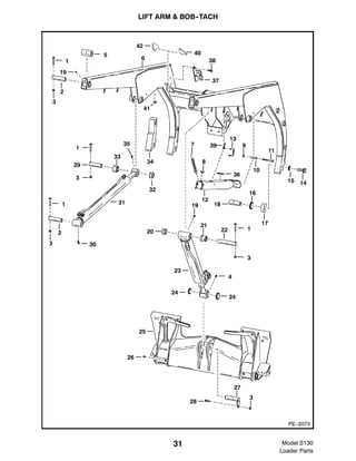
- Tracks: The robust bands that facilitate movement, designed to provide traction and distribute weight.
- Sprockets: Circular gears that engage with the tracks, aiding in the movement of the machinery.
- Idlers: Wheels that support the track system, helping to maintain the track’s alignment and tension.
- Rollers: Components that reduce friction between the track and the ground, ensuring smoother operation.
Tensioning Mechanisms
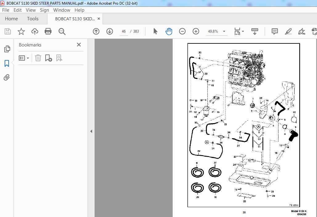
Proper tensioning is crucial for the effective functioning of the track system. Maintaining the correct tension prevents excessive wear and enhances performance.
- Tensioning Cylinder: This hydraulic element adjusts the track tension, ensuring optimal tightness.
- Adjustable Bolts: Used to fine-tune the tension, allowing for easy adjustments based on operational needs.
- Track Adjusters: Devices that facilitate quick changes to the track tension, enhancing convenience during maintenance.
Identifying Key Parts of the Boom Assembly
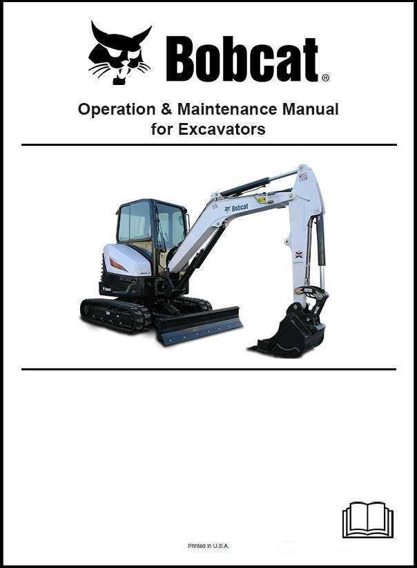
The boom assembly is an essential component of various heavy machinery, playing a crucial role in lifting and maneuvering loads. Understanding its key elements is vital for maintenance and operational efficiency. This section will explore the primary components found within the boom assembly, highlighting their functions and importance.
Component Description Arm The elongated structure that extends from the main body, allowing for vertical and horizontal movement. Pivot Pin A cylindrical fastener that connects the arm to the main chassis, facilitating rotation. Cylinder The hydraulic unit that provides the force necessary to lift and lower the boom. Linkage A series of rods and joints that connect different parts of the assembly, ensuring synchronized movement. Brace Support structures that reinforce the boom, enhancing stability during operations. Cab and Operator Controls Diagram Overview
This section provides an insight into the various components and functionalities associated with the operator’s enclosure and control mechanisms of compact machinery. Understanding these elements is crucial for effective operation and maintenance.
Key Features of the Operator’s Enclosure
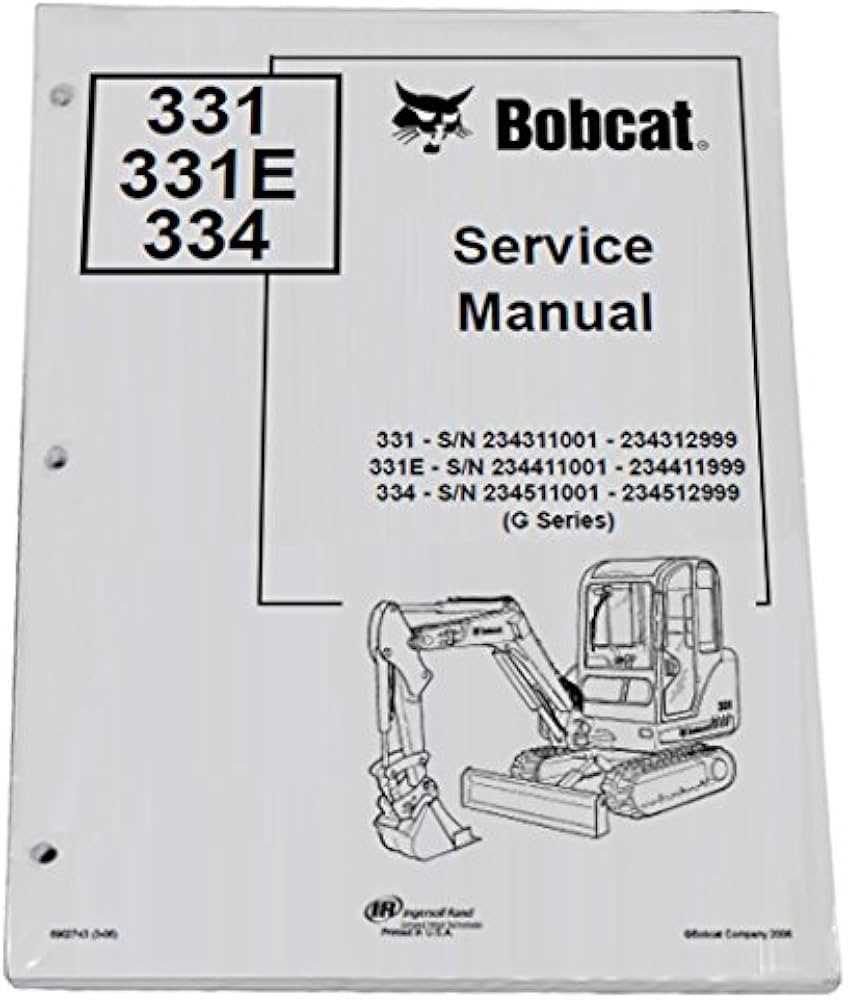
- Spacious design for enhanced comfort during operation
- Noise insulation to minimize external sound interference
- Ergonomic layout for easy access to controls
- Visibility enhancements for improved safety
Control Mechanisms
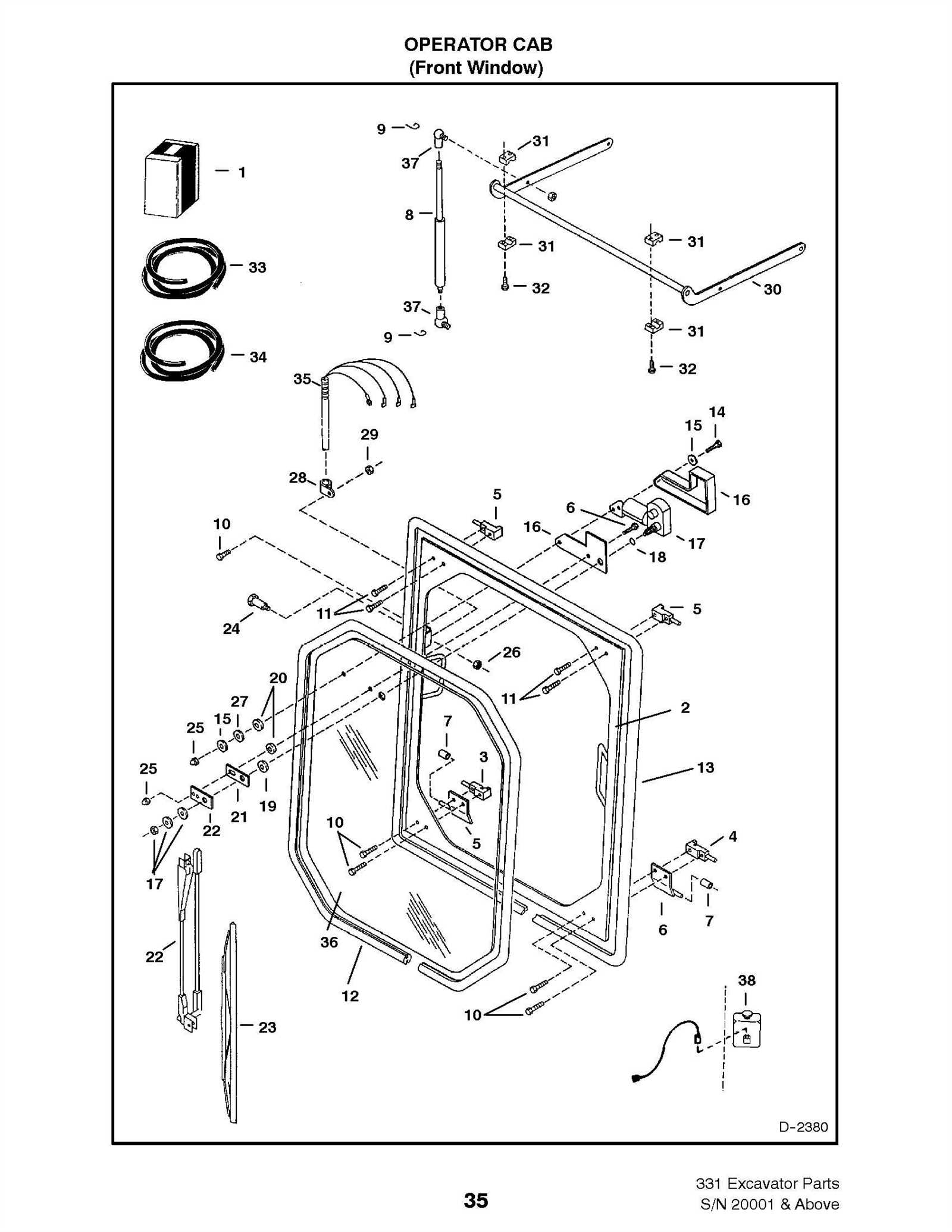
- Joystick controls for precise maneuvering
- Foot pedals for engine speed and hydraulic functions
- Control levers for various attachments and implements
- Dashboard indicators for monitoring system performance
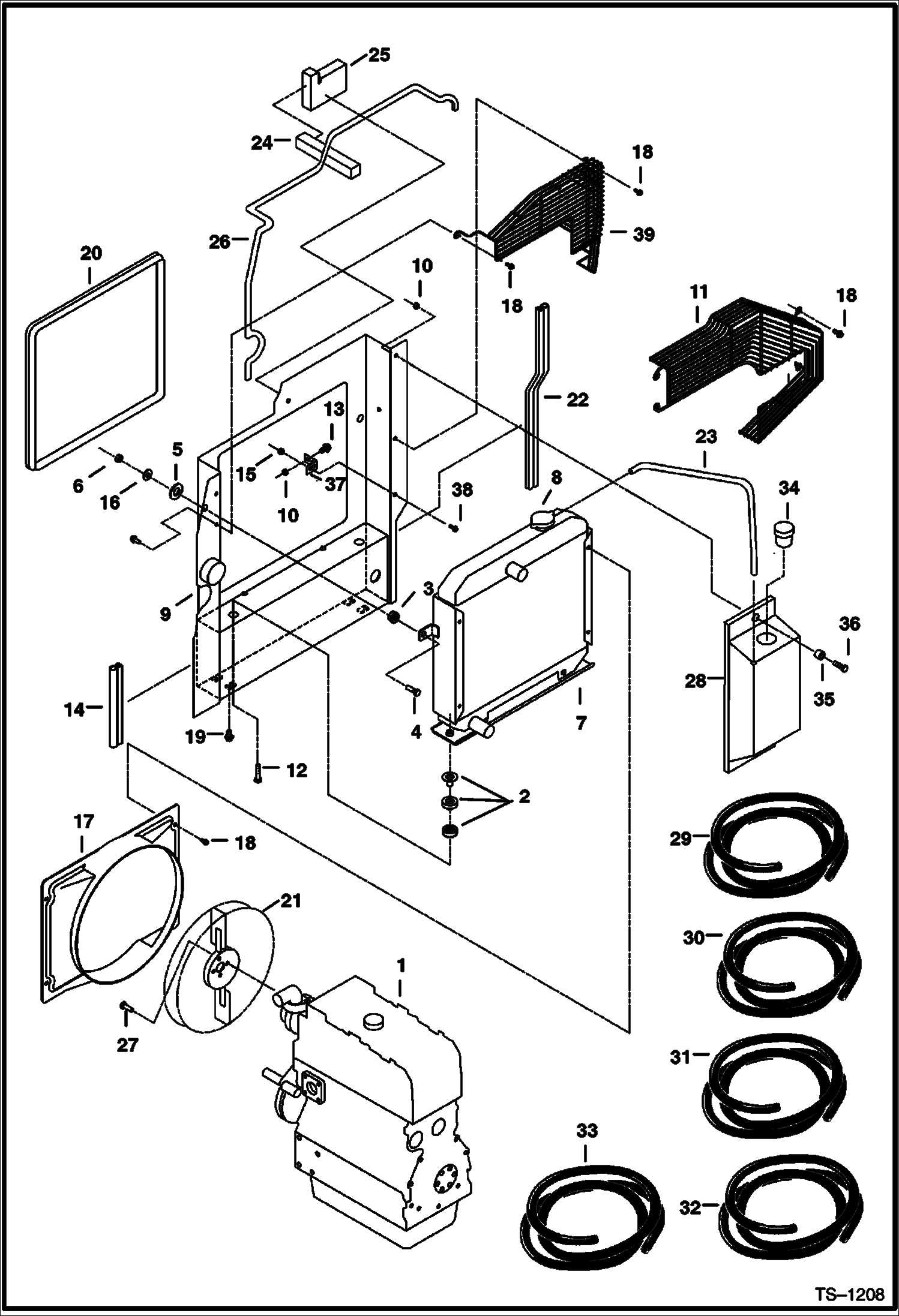
Cooling System Parts and Connections
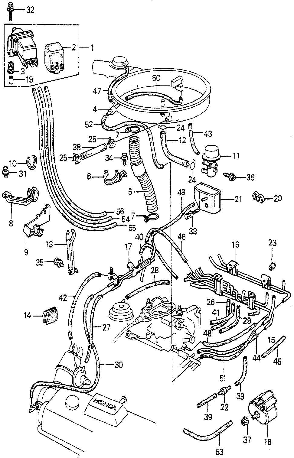
The efficiency of any machinery relies heavily on its ability to maintain optimal operating temperatures. A well-functioning cooling system plays a crucial role in preventing overheating and ensuring the longevity of the engine. Understanding the components and their interconnections is essential for effective maintenance and troubleshooting.
Key elements of a cooling mechanism include the radiator, water pump, hoses, and thermostat. Each component serves a specific function in regulating temperature. The radiator dissipates heat from the engine coolant, while the water pump circulates the fluid throughout the system. Hoses connect these parts, allowing for a seamless flow of coolant, and the thermostat monitors and controls the temperature.
Proper connections between these components are vital for maintaining pressure and ensuring efficient operation. Leaks or blockages can lead to performance issues, highlighting the importance of regular inspections and prompt repairs. Keeping the cooling system in optimal condition is fundamental to the overall health of the machinery.
Understanding the Hydraulic System Structure
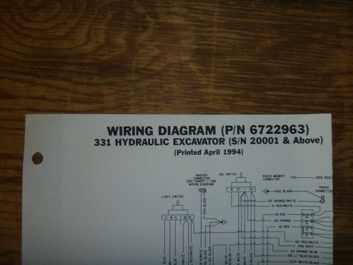
The hydraulic system plays a crucial role in machinery, offering the power needed to operate various components efficiently. By utilizing fluid pressure, this system transfers energy to move parts and perform tasks with precision. Its design ensures the smooth transmission of power, enabling machines to handle even the most demanding operations.
Core Components and Their Functions
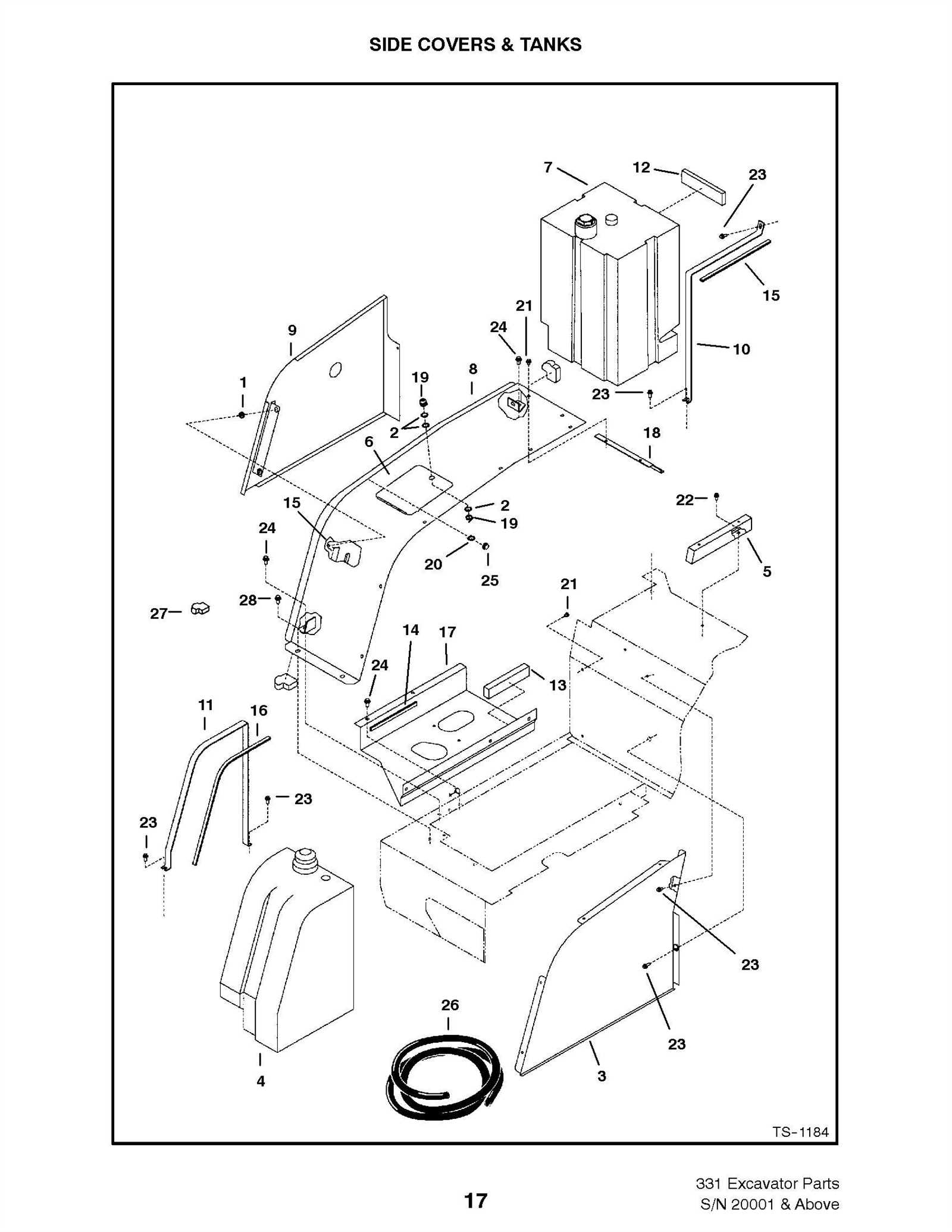
A typical hydraulic system consists of several key elements that work in unison. These include pumps, valves, cylinders, and hoses, each with specific roles. The pump generates the necessary pressure, while valves control the flow of fluid. Cylinders convert hydraulic energy into mechanical force, and hoses ensure the seamless movement of fluid between components.
Efficiency and Maintenance
Maintaining optimal performance in a hydraulic system requires regular checks and proper upkeep. Leaks, pressure drops, or contamination can significantly reduce efficiency. Regular maintenance helps prevent malfunctions and extends the longevity of the system, ensuring reliable operation.
Engine Assembly Breakdown for the Bobcat 331
The engine assembly consists of multiple interconnected components that work together to ensure smooth operation. Understanding the layout and the function of each element within the system is essential for effective maintenance and troubleshooting.