bobcat t450 parts diagram

When it comes to maintaining and repairing modern construction equipment, having a clear understanding of how each element is interconnected is essential. The ability to visualize the various elements involved in a machine’s design allows for easier identification of what might need attention during service or replacement.

In this section, we’ll explore the detailed layout of a compact piece of machinery. By breaking down each component, you’ll gain a clearer picture of how they work together, ensuring efficient performance and minimizing downtime. Whether you are troubleshooting or performing regular maintenance, understanding these key aspects will streamline the entire process.

From the engine block to the hydraulic system, every element has its role to play. By familiarizing yourself with the internal setup, you can avoid costly mistakes and keep the equipment in peak condition for years to come. Let’s take a closer look at the structure to deepen your knowledge and simplify any future

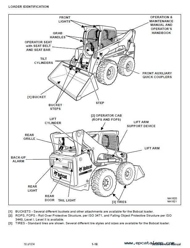
Understanding the Bobcat T450 Components
bobcat t450 parts diagram

In this section, we will explore the various elements that make up this versatile machine, providing insight into how these individual pieces contribute to its overall functionality. Each component is carefully designed to ensure optimal performance, whether it’s used in demanding tasks or routine operations.

Key Systems Overview
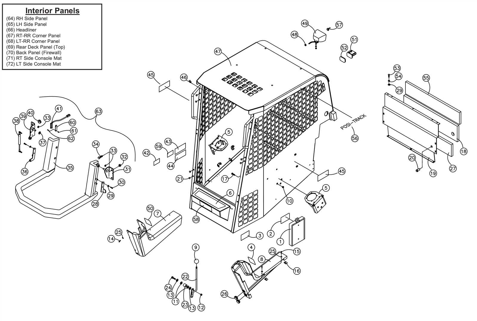
bobcat t450 parts diagram

The machine’s key systems include its propulsion unit, control mechanisms, and work attachments. These systems work in harmony to provide efficiency, power, and precision. The propulsion unit drives the machine forward, while the control mechanisms allow for smooth operation. Work attachments can be swapped easily to suit a variety of tasks.

Component Breakdown
bobcat t450 parts diagram

Below is a breakdown of the main components, showcasing how each contributes to the machine’s performance and ease of use:

Component Function
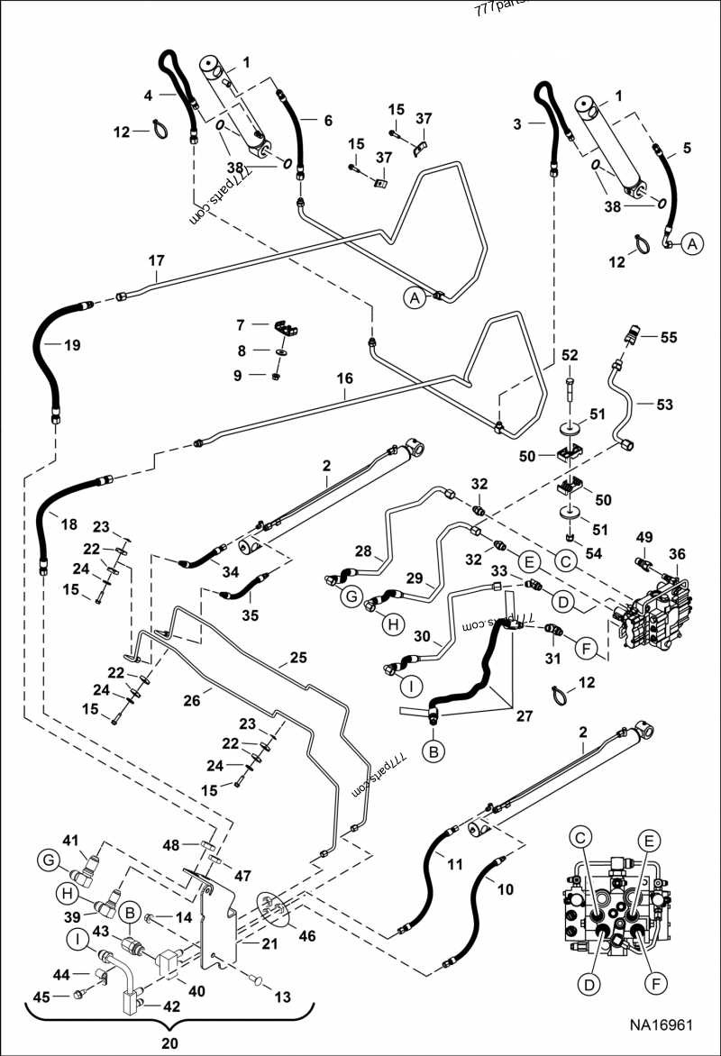
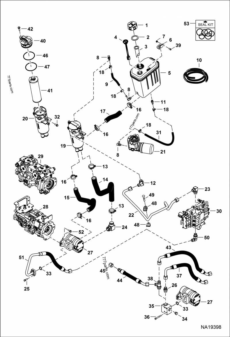
Detailed Layout of Hydraulic System

The hydraulic system is a critical component in the efficient operation of machinery. It is designed to facilitate the movement of various mechanical parts by transmitting force through pressurized fluid. Understanding its layout provides insight into the flow of energy and how it powers essential functions. This section will outline the primary connections and flow paths within this system, explaining how each element works together to ensure smooth performance.

Main Hydraulic Components

The hydraulic system is composed of key elements such as the pump, valves, and cylinders. The pump is responsible for generating the required fluid pressure, which is then directed through a series of valves that control the flow and direction of the hydraulic fluid. Cylinders convert this pressurized fluid into mechanical force,

Track Assembly Overview for Bobcat T450

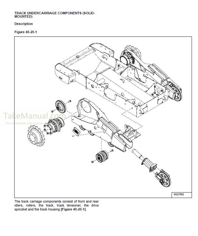
The track system plays a crucial role in the movement and stability of the machine. This section will cover the essential components involved in the assembly and how they contribute to the overall performance of the vehicle on various terrains.

The track structure is designed for durability, allowing the machine to handle heavy loads while maintaining optimal traction. The key components include the rubber tracks, rollers, idlers, and drive sprockets, each working together to provide smooth movement and stability.

Tracks provide grip and distribute weight evenly, preventing excessive wear and ensuring a firm hold on the ground. The rollers support the tracks, allowing them to rotate freely and absorb impact from uneven surfaces. Idlers help maintain tension in the track system, while the drive sprockets ensure effective power transmission from the engine to the track, propelling the vehicle forward.

This interconnected assembly is vital for maximizing operational efficiency

Exploring the Engine Compartment Design

bobcat t450 parts diagram

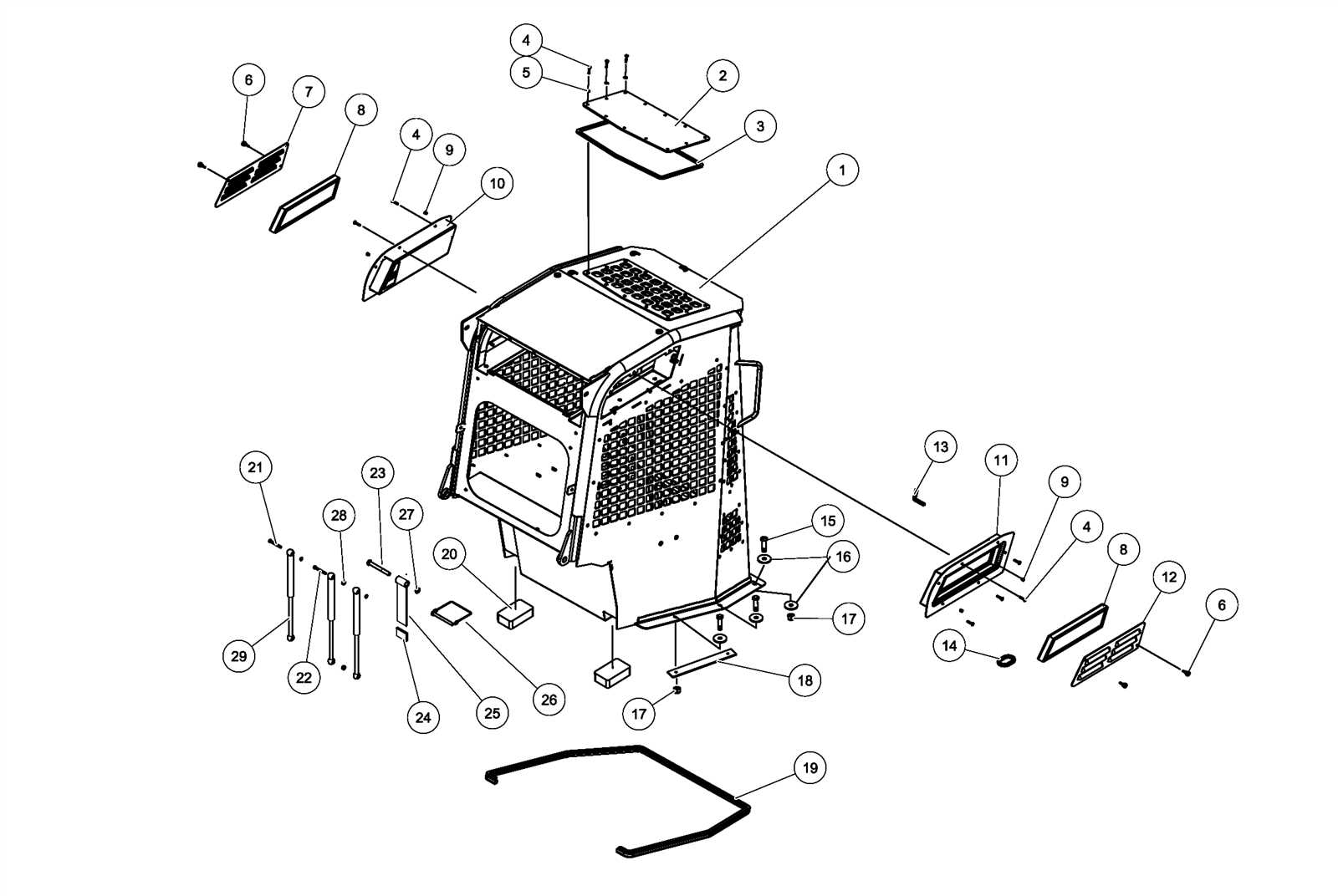
The engine compartment of modern machinery plays a critical role in housing and protecting the core power system. Its design is crafted with both functionality and maintenance in mind, ensuring that key components are easily accessible for service while maintaining a compact and efficient layout. This thoughtful arrangement supports optimal performance and durability, even in demanding working environments.

Accessibility and Layout are essential factors in this space. The compartment is structured to provide quick access to essential elements, minimizing downtime during routine inspections or repairs. Well-placed panels and latches offer seamless entry, allowing technicians to work efficiently.

In addition to accessibility, the ventilation system within the compartment is des

Analyzing the Cooling System Components

bobcat t450 parts diagram

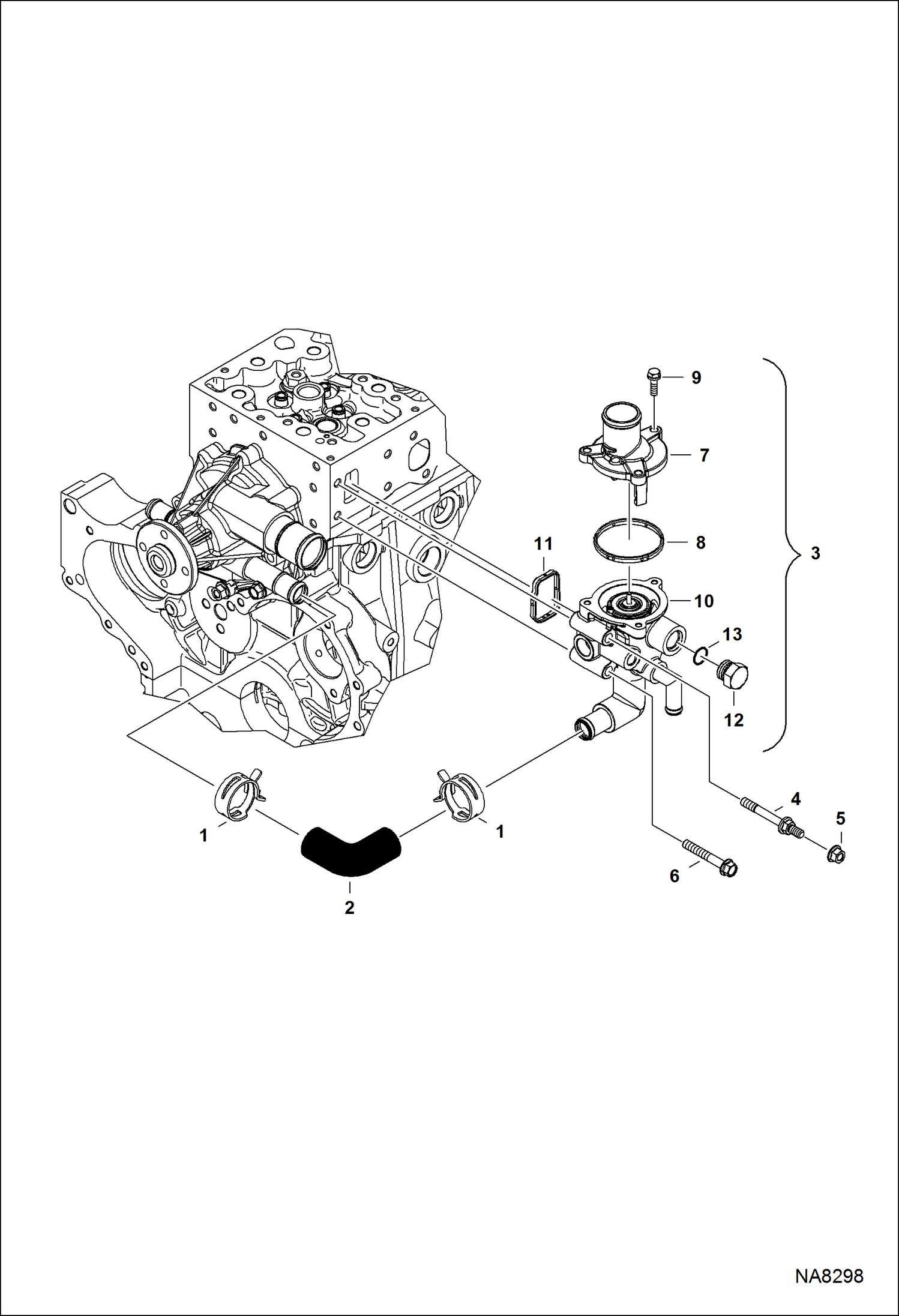
The cooling system is a vital part of any equipment, ensuring that the internal mechanisms operate within the proper temperature range. By keeping the engine cool and preventing overheating, it safeguards the longevity of various mechanical elements. This section explores the primary components involved in maintaining temperature stability and their roles within the system.

Main Elements of the Cooling System

bobcat t450 parts diagram

Several essential elements work together to regulate temperature. These components ensure that heat generated during operation is efficiently dispersed. Proper maintenance of these components is crucial to prevent failures caused by excessive heat buildup.

Component Function
Radiator Disperses heat from the coolant, ensuring the temperature is reduced before recirculation.
Thermost

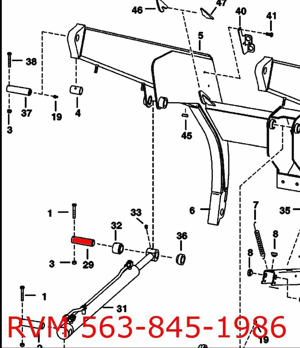
Functionality of the Lift Arm Assembly

bobcat t450 parts diagram

The lift arm assembly plays a crucial role in the operation of various heavy machinery, enabling the raising and lowering of attached implements. This system is essential for tasks that require significant vertical movement, such as lifting, digging, or loading materials. Its design ensures stability and control, allowing operators to perform their tasks efficiently and safely.

Components of the Lift Arm Assembly

bobcat t450 parts diagram

The lift arm assembly consists of several key components that work together to achieve its functionality. These include the lift arms, hydraulic cylinders, and pivot points. Each part contributes to the overall performance of the assembly, ensuring smooth operation during various tasks.

Operational Mechanism

The operational mechanism of the lift arm assembly relies on hydraulic power. When activated, hydraulic fluid is directed into the cylinders, causing the lift arms to extend or retract. This process allows for precise control over the height and angle of the attached implement, enhancing the machine’s versatility.

Component Function
Lift Arms Support the implement and provide the primary lifting motion.
Hydraulic Cylinders Convert hydraulic pressure into mechanical force for movement.
Pivot Points Allow the lift arms to rotate and provide stability during operation.

Electrical System Breakdown for Bobcat T450

The electrical framework of a compact utility machine plays a vital role in its overall functionality and performance. Understanding the intricate components and their interconnections is essential for effective maintenance and troubleshooting. This section delves into the various elements that comprise the electrical setup, providing insights into their roles and importance.

Key Components of the Electrical Setup

At the heart of the electrical configuration is the battery, which supplies the necessary energy for the operation of various systems. This energy is distributed through a network of wiring harnesses, ensuring that each part receives the power required for optimal performance. Additionally, sensors and control modules work in tandem to monitor and regulate different functions, enhancing operational efficiency.

Troubleshooting Common Electrical Issues

bobcat t450 parts diagram

Identifying and resolving electrical problems can be challenging, yet essential for maintaining the functionality of the machinery. Common issues include disconnected wires or faulty connectors, which can disrupt the flow of energy. Regular inspections and diagnostics help in pinpointing these issues, allowing for timely repairs and ensuring that all components operate harmoniously.

Maintenance Tips for the Fuel System

bobcat t450 parts diagram

Ensuring the optimal performance of the fuel delivery system is crucial for the efficient operation of your machinery. Regular upkeep and attention to this vital component can prevent issues that lead to reduced efficiency and costly repairs. Below are essential practices to help maintain the fuel system effectively.

Regular Inspection

bobcat t450 parts diagram

Consistent examination of the fuel system components is necessary to identify wear and potential failures. Check for leaks, cracks, and corrosion, especially in hoses and connectors. Pay attention to the fuel filter and replace it as needed to ensure clean fuel flow.

Fuel Quality Management

Using high-quality fuel is fundamental for the longevity of the engine. Avoid mixing different fuel types and ensure the fuel tank is filled with fresh fuel. Additionally, add a fuel stabilizer to prevent degradation during periods of inactivity.

Maintenance Task Frequency Notes
Inspect hoses and connectors Monthly Look for signs of wear or leaks.
Replace fuel filter Every 250 hours Follow manufacturer’s guidelines.
Clean fuel tank Annually Remove contaminants and sediment.
Check fuel lines Monthly Ensure no blockages are present.

Key Parts in the Operator’s Cabin

bobcat t450 parts diagram

The operator’s cabin of a compact machine is designed to enhance comfort, control, and visibility for efficient operation. Understanding the essential components within this space is crucial for effective use and maintenance.

  • Control Panel: This is the central interface where the operator manages various functions and settings of the equipment.
  • Seating: Ergonomically designed seats provide support during extended work periods, allowing for adjustments to suit individual preferences.
  • Instrumentation: Gauges and displays offer real-time information on machine performance, including engine status and hydraulic levels.
  • Foot Pedals: These are used to control speed and direction, providing precise maneuverability during operations.
  • Steering Wheel: A well-placed wheel enables accurate handling and navigation of the machine in tight spaces.
  • Visibility Features: Large windows and mirrors improve sightlines, aiding in awareness of surroundings and enhancing safety.
  • Storage Compartments: Conveniently located areas allow operators to keep tools and personal items organized and within reach.

By familiarizing oneself with these crucial elements, operators can ensure optimal functionality and comfort while managing their machinery.

Steering Mechanism and Control Details

The steering system is a vital component that influences the maneuverability and stability of a machine. Understanding its design and function is essential for effective operation and maintenance. This section delves into the intricacies of the steering mechanism, highlighting its key features and control aspects.

Overview of the Steering System

bobcat t450 parts diagram

The steering assembly typically consists of various interconnected parts that work together to enable precise directional changes. Key elements include:

  • Steering wheel or lever
  • Linkage components
  • Hydraulic or mechanical actuators

Each of these components plays a crucial role in translating user inputs into corresponding movements of the wheels or tracks.

Control Mechanisms

bobcat t450 parts diagram

Control systems are designed to provide operators with intuitive handling. Important features include:

  1. Feedback Mechanisms: Offer resistance or response based on the steering angle.
  2. Adjustable Sensitivity: Allow customization of steering responsiveness for various tasks.
  3. Safety Features: Ensure automatic adjustments in extreme conditions to maintain control.

Understanding these control details is essential for effective operation and safety during use.

Understanding the Boom and Attachment Points

bobcat t450 parts diagram

The boom serves as a crucial component in various machinery, facilitating lifting and extending capabilities. Its design plays a significant role in the overall functionality of equipment, enabling operators to perform a wide range of tasks efficiently. Understanding the different aspects of the boom and how it connects with attachments is essential for maximizing operational effectiveness and ensuring safety.

Key Features of the Boom

  • Construction: Typically crafted from robust materials to withstand heavy loads and stresses.
  • Articulation: Many models feature an articulated design, allowing for enhanced maneuverability and reach.
  • Hydraulic System: Equipped with hydraulic mechanisms that enable smooth movement and control.

Attachment Points Explained

bobcat t450 parts diagram

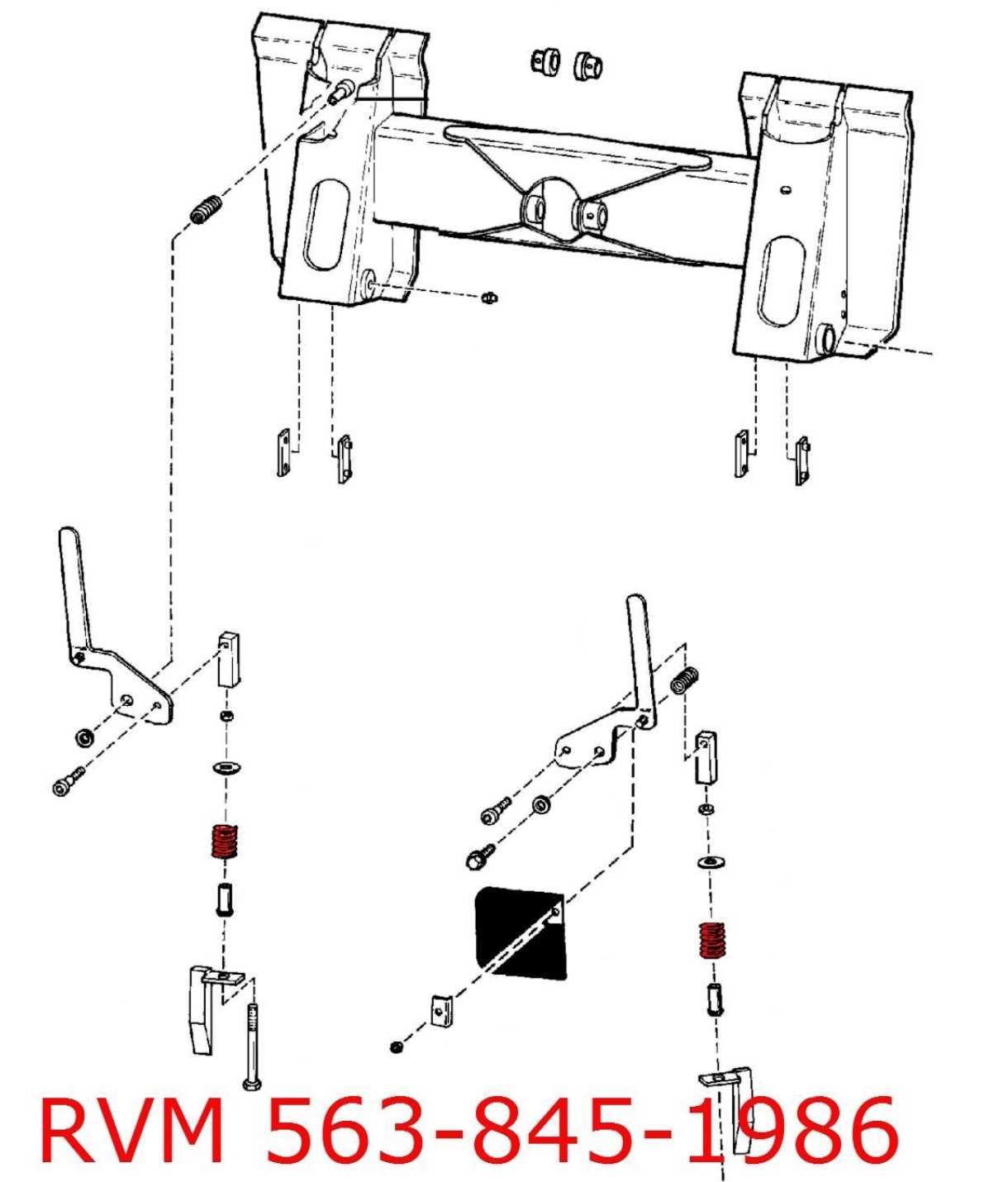
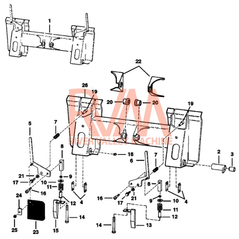
Attachment points are integral for connecting various implements to the boom. Understanding these points is vital for safe and effective operation.

  • Types of Attachments:
    • Buckets for digging and moving materials.
    • Forks for lifting and transporting pallets.
    • Brush cutters for vegetation management.
  • Connection Mechanisms:
    • Pin and latch systems for secure attachment.
    • Quick-attach systems for rapid changes between tools.

Familiarity with the boom’s structure and the various attachment points will enhance productivity and safety during operations, ensuring that users can effectively adapt their machinery for different tasks.

Brake System Components and Layout

bobcat t450 parts diagram

The braking system is a crucial aspect of any machinery, ensuring safety and control during operation. This section explores the various elements that comprise the braking mechanism, detailing their arrangement and function within the overall system. Understanding these components is essential for effective maintenance and troubleshooting.

At the core of the braking system are the brake pads, which create friction against the rotors when engaged. This friction generates the necessary force to slow down or stop the machine. Additionally, the hydraulic lines are vital, transferring pressure from the brake pedal to the braking components, ensuring a responsive and reliable braking action.

The layout of the braking assembly typically includes a master cylinder, which converts the force from the operator’s foot into hydraulic pressure. This pressure is then directed to the wheel cylinders, where it activates the brake shoes or calipers. Each of these components is strategically placed to optimize performance and enhance safety during operation.

Regular inspection and maintenance of the braking system components are imperative to ensure efficient functionality. Proper care not only prolongs the lifespan of the individual parts but also guarantees the overall safety and reliability of the machinery.

Examining the Air Filtration System

The air filtration system plays a crucial role in maintaining the optimal performance of machinery by ensuring that clean air is supplied to the engine. This section delves into the components and functions of this vital system, highlighting its importance in overall operational efficiency.

Key components of the air filtration system include:

  • Air Filter: The primary element responsible for trapping dust, dirt, and other contaminants.
  • Pre-Filter: A secondary filter that captures larger particles before they reach the main air filter.
  • Intake Duct: The pathway through which air enters the filtration system.
  • Seals and Gaskets: These ensure that no unfiltered air bypasses the filter, maintaining the integrity of the system.

Maintaining this system is essential for:

  1. Enhancing Performance: Clean air improves combustion efficiency, leading to better engine performance.
  2. Extending Equipment Life: Proper filtration reduces wear and tear on engine components.
  3. Reducing Emissions: A well-maintained air system contributes to lower emissions, supporting environmental compliance.

Regular inspection and replacement of filters, along with cleaning of the intake duct, are recommended to ensure the system functions effectively. By understanding and maintaining the air filtration system, operators can enhance the longevity and efficiency of their machinery.