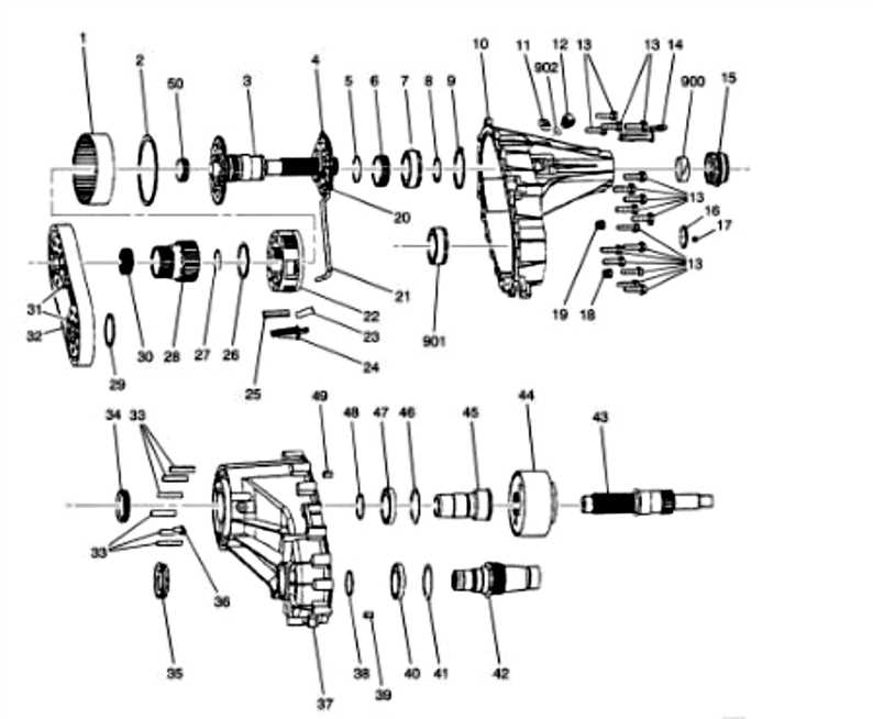
Delving into the intricate design and operational features of this mechanical component reveals the essential connections that ensure its functionality. Exploring the structure and organization of each element provides a clearer understanding of how various parts come together to deliver precise performance in various conditions. This section aims to break down the core elements that make up this system, giving insight into its operation and the relationship between individual components.
By focusing on the unique assembly, it becomes easier to grasp the roles played by each distinct piece. This approach helps identify the significance of each section and its contribution to the overall mechanical efficiency. Whether it’s the central hub or smaller, supporting mechanisms, every element serves a purpose. The following analysis will shed light on the interplay between these crucial elements and the overall impact they have on the system’s performance.
Understanding the Structure of the Bw4446
The mechanism in question is a highly sophisticated component designed to manage power distribution effectively. It consists of multiple interlocking elements that work in harmony to ensure smooth operation under varying conditions. This section will explore the internal layout, detailing how each component interacts to provide a seamless driving experience.
- First, the primary casing protects all internal elements from external damage and houses the essential moving parts.
- Within the core, a series of gears and clutches are responsible for transferring force efficiently, adjusting power flow between different sections of the system.
- The control module is the brain behind the operation, receiving signals and adjusting the mechanics as needed for optimal performance.
- Fluid channels circulate
Components Inside the Transfer Case
The mechanism under discussion contains various key elements that work together to manage power distribution between the vehicle’s front and rear wheels. These internal components ensure smooth operation and adjust the torque, adapting to different driving conditions.
- Main Shaft: A central axis that transfers energy to different sections of the drivetrain.
- Planetary Gear Set: This assembly adjusts the gear ratios, allowing for changes in speed and torque distribution.
- Clutch Pack: A series of friction plates that engage and disengage to modulate the flow of power between the wheels.
- Chain Drive: Responsible for linking the internal shafts, ensuring synchronized movement of components.
- Shift Fork: A movable arm that directs the position of
Exploring Key Mechanical Elements
In this section, we will delve into the core mechanical components that contribute to the efficient operation of the system. Understanding these individual elements is crucial for ensuring the overall functionality and performance of the unit, as each part plays a specific role in the mechanical coordination.
- Gear Assemblies: These form the heart of the mechanism, responsible for transferring torque and ensuring the smooth interaction between rotating elements.
- Shafts and Bearings: Vital for stabilizing the rotating components, they reduce friction and wear, thus prolonging the lifespan of the system.
- Seals and Gaskets: These components ensure that fluids and contaminants do not enter or leak from sensitive areas, maintaining internal efficiency and protection.
- Synchronization Mechanisms: These elements work to align different parts of the system, ensuring they function
Role of Bearings and Gears
The efficiency and functionality of mechanical systems heavily rely on the seamless interaction between rotational components. These essential elements enable the smooth transfer of motion and energy, ensuring optimal performance even under demanding conditions.
Bearings: Ensuring Smooth Operation
Bearings are fundamental to minimizing friction between moving elements. They allow rotational movements with reduced resistance, preventing excessive wear and tear. This significantly extends the lifespan of critical components and ensures the system operates efficiently under various loads.
Gears: Transmitting Power
Gears serve as the primary means of transferring motion and force between interconnected components. By altering torque and speed, gears enable precise control over the system’s performance. Their design
Identifying Key Shafts and Seals
The structural integrity and performance of any mechanical assembly heavily depend on the proper alignment and functionality of its internal components. Among the most crucial elements are the various cylindrical connectors and protective barriers that ensure smooth motion and prevent leaks. Understanding these components and their placement is essential for efficient maintenance and repair.
Crucial Cylindrical Connectors
These connectors serve as the backbone of the system, transmitting power and ensuring rotational movement between different sections. Precision in their installation is key to avoiding operational issues. Their design and function allow them to handle significant stress while maintaining stability within the system.
Protective Barriers
These barriers are essential for preventing contamination and ensuring that fluids remain contained within specific areas. Their role is not only to preserve the internal environment but also to extend the lifespan of surrounding components by reducing friction and exposure to external elements
Function of the Chain and Sprockets
The interconnection between the loop mechanism and the cogwheels plays a crucial role in transmitting motion and power within a mechanical system. This synergy ensures that energy is efficiently transferred from one component to another, enabling smooth operation and optimal performance.
The loop mechanism serves as a flexible conduit that wraps around the cogwheels, facilitating the transfer of rotational force. As one cogwheel rotates, it engages with the loop, causing it to move in tandem. This interaction translates rotational motion into linear movement, allowing various parts of the system to work harmoniously.
Moreover, the size and design of the cogwheels can significantly influence the overall performance of the mechanism. By adjusting the ratio between the sizes of the loop and the cogwheels, engineers can achieve different speed and torque outputs, tailoring the system’s functionality to meet specific requirements.
In essence, the collaboration between the loop mechanism and the cogwheels is fundamental to the efficient operation of numerous machines, from simple devices to complex machinery, highlighting their importance in mechanical engineering.
Clutch and Torque Management Mechanism
The effective operation of a vehicle’s powertrain relies heavily on the integration of a mechanism responsible for managing rotational force and engagement. This system plays a critical role in ensuring smooth transitions between various modes of operation, ultimately enhancing performance and efficiency.
At its core, this mechanism consists of several key components, each contributing to the overall functionality:
- Engagement System: This part is responsible for connecting and disconnecting power from the engine to the drivetrain, allowing for seamless shifts in power delivery.
- Force Distribution: A critical feature that balances torque across the different wheels, optimizing traction and stability during acceleration and cornering.
- Adaptive Controls: Utilizing sensors and control units, this component adjusts the engagement and torque distribution based on driving conditions, enhancing responsiveness and handling.
- Durability and Wear Resistance: Constructed from materials designed to withstand high stress and heat, ensuring long-lasting performance under various driving scenarios.
By effectively coordinating these elements, the mechanism not only improves drivability but also contributes to the overall longevity of the vehicle’s drivetrain. Regular maintenance and inspection of these components are essential for optimal operation and reliability.
Examining Sensors and Electrical Connections
Understanding the functionality of various sensors and their associated electrical connections is crucial in ensuring optimal performance of complex systems. These components play a significant role in monitoring and controlling different parameters, providing essential data that influences the overall operation. A thorough exploration of these elements can unveil insights into their interdependencies and the impact they have on system reliability.
Types of Sensors
Sensors are designed to detect specific changes in the environment, converting physical phenomena into readable signals. Common types include temperature, pressure, and position sensors, each serving a distinct purpose. Their correct placement and connection are vital for accurate data collection.
Electrical Connections Overview
The effectiveness of sensor operation often relies on the integrity of electrical connections. Proper wiring and connectors facilitate seamless communication between sensors and control units, ensuring that data transmission is both reliable and efficient. Regular inspection of these connections can prevent malfunctions and enhance system longevity.
Sensor Type Function Common Applications Temperature Measures thermal conditions HVAC systems, automotive engines Pressure Monitors force exerted by fluids Industrial processes, hydraulic systems Position Detects location or movement Robotics, automation equipment Lubrication System and Its Parts

The efficiency and longevity of machinery are significantly influenced by its lubrication mechanism. This crucial system ensures that moving components operate smoothly, reducing friction and wear. A well-maintained lubrication system not only enhances performance but also contributes to the overall reliability of the equipment.
Key Components of the Lubrication Mechanism
The lubrication setup comprises several essential elements, each playing a specific role in maintaining optimal function. Understanding these components is vital for effective maintenance and troubleshooting.
Component Description Oil Pump Responsible for circulating lubricant throughout the system, ensuring that all moving parts receive adequate protection. Filters Remove contaminants from the lubricant, preventing damage to the components and maintaining system integrity. Oil Reservoir Holds the lubricant and allows for easy access and monitoring of fluid levels. Distribution Lines Transport lubricant from the reservoir to various components, ensuring thorough coverage. Importance of Regular Maintenance
Routine inspection and maintenance of the lubrication system are crucial to prevent failures and ensure optimal performance. Regularly checking fluid levels, replacing filters, and examining components for wear can significantly extend the lifespan of machinery.
How to Maintain and Replace Parts
Proper upkeep and timely substitution of components are essential for ensuring the longevity and efficiency of any mechanical system. Regular inspections and preventive measures can help identify wear and tear before they escalate into significant issues. Understanding how to effectively care for and replace essential elements can save time and resources in the long run.
Routine Inspection
Conducting regular checks is vital for spotting potential problems early. Look for signs of damage, such as cracks or unusual wear, and ensure that all components are securely fastened. Keeping a maintenance log can also help track the condition and performance of each element over time.
Replacement Procedures
When it’s time to swap out any part, always refer to the manufacturer’s guidelines for the correct procedure. Gather the necessary tools beforehand, and ensure that the replacement is compatible. During installation, take care to align all pieces correctly, and double-check connections to maintain optimal functionality.
Troubleshooting Common Component Failures
When dealing with mechanical systems, it is essential to identify and resolve issues that may arise from individual elements. Regular maintenance and prompt diagnostics can significantly enhance the lifespan and functionality of the entire unit. This section aims to provide a structured approach to recognizing typical malfunctions and their underlying causes.
Step 1: Visual Inspection is the first line of defense. Examine the various components for any signs of wear, corrosion, or damage. Look for loose connections or misalignments that may hinder performance. Taking note of any unusual odors or sounds can also provide clues to potential issues.
Step 2: Functional Testing allows for a more in-depth analysis. By operating the system under normal conditions, you can observe how each part interacts. Pay attention to any irregularities, such as inconsistent performance or failure to respond. This may indicate a failing component that requires further investigation.
Step 3: Electrical Checks are crucial for systems with electronic components. Use a multimeter to measure voltage and resistance at various points. This can help pinpoint electrical failures, such as shorts or open circuits, that could lead to malfunctions.
Step 4: Consult Documentation provides valuable information regarding specifications and troubleshooting steps. Refer to manuals or technical resources for guidance on potential problems and solutions specific to the system being evaluated.
By following these systematic approaches, you can efficiently identify and address common failures, ensuring optimal performance and reliability of the overall assembly.