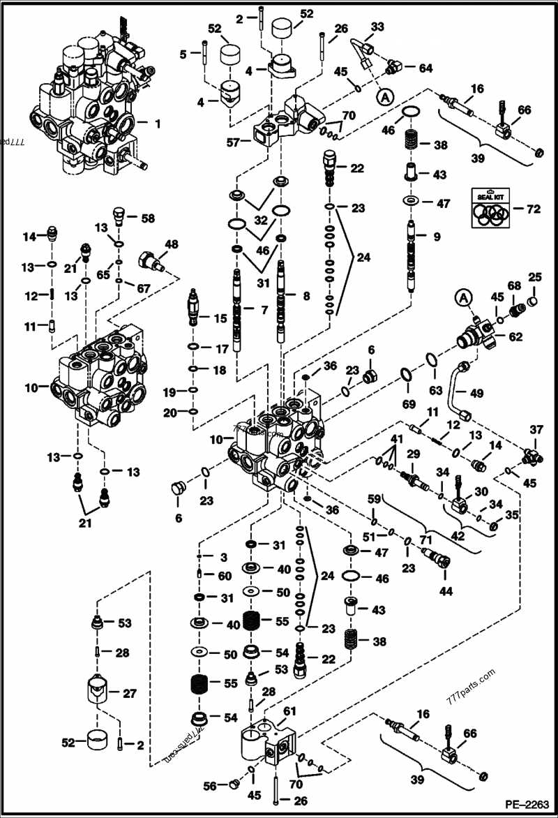
In complex mechanical systems, it is essential to understand how various control mechanisms work together to manage the flow of energy. These systems are designed to precisely regulate the movement of fluids within industrial machinery, ensuring smooth and efficient operation. The key elements in this process often involve multiple interconnected components that serve to direct, block, or adjust the flow of liquid or gas depending on the system’s requirements.
The inner workings of such systems can be intricate, with several critical parts playing a role in managing the direction and pressure. Each element must be carefully constructed and arranged to guarantee optimal performance. Studying the arrangement and function of these elements provides valuable insight into maintaining and troubleshooting mechanical setups effectively.
By analyzing how these control systems are constructed and how their parts interact, it becomes easier to identify potential issues or inefficiencies in operation. Understanding the core principles behind these designs can significantly aid in ensuring long-term reliability and
Hydraulic Valve Functionality Overview
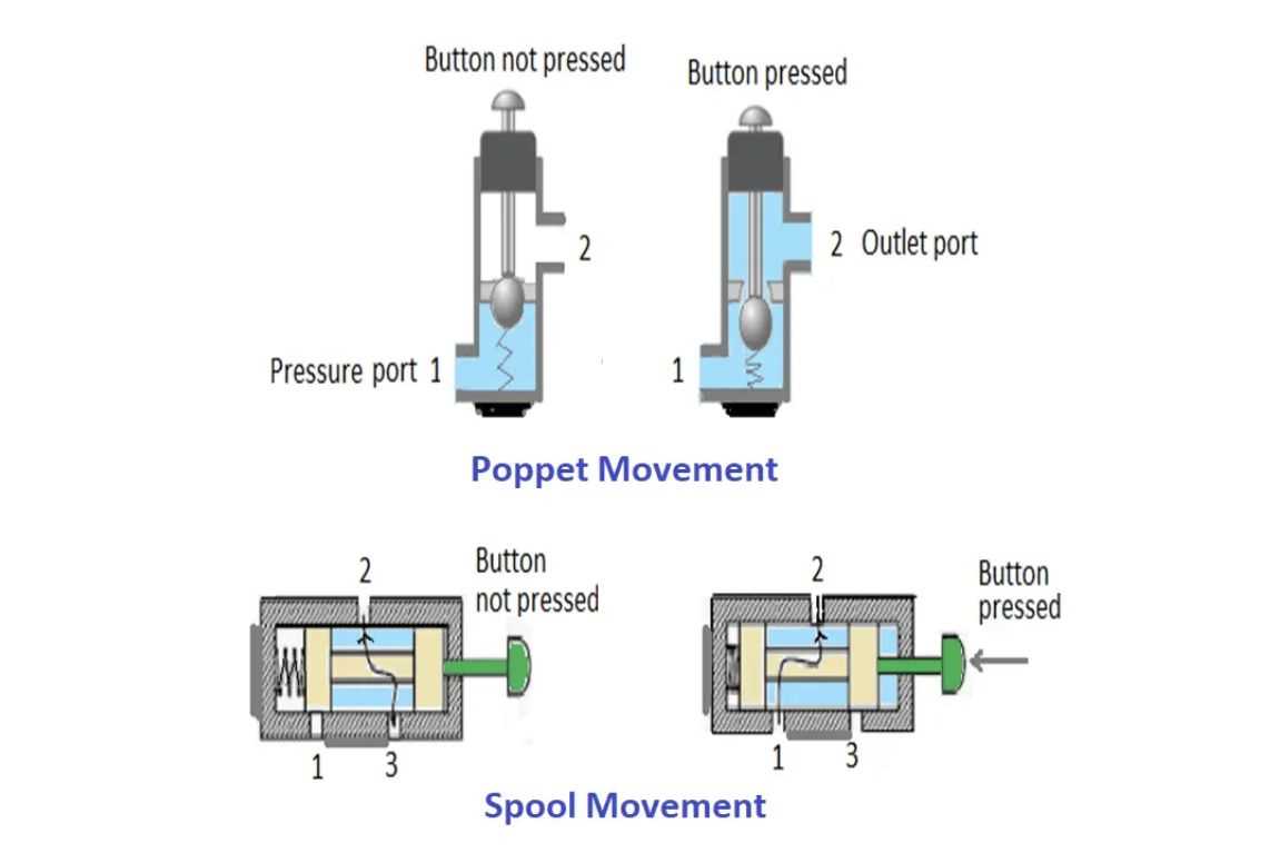
In mechanical systems, control units are designed to regulate the flow of fluids, ensuring that force is properly distributed to achieve desired movements. These devices play a crucial role in directing energy within machines, guiding fluid streams where needed for specific actions.
Their primary function is to manage pressure and volume, adjusting the force and speed at which fluid is delivered. By opening, closing, or restricting pathways, they maintain balance and control over various operations. These systems work under precise conditions to ensure seamless functionality in different machinery applications.
Main Components of a Cross Hydraulic Valve
Understanding the core elements of this fluid control mechanism is crucial for efficient system operation. Each component plays a specific role, ensuring smooth and precise management of liquid flow under pressure. These elements are designed to work together, enhancing performance and reliability in different applications.
Key Structural Elements
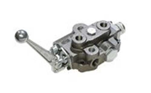
The structure consists of several essential components that enable fluid regulation. These include an actuator, responsible for initiating movement, and a control chamber that guides the fluid direction based on input signals. In addition, sealing elements are critical for preventing leaks and ensuring system integrity.
Functional Components
The functional aspects involve a mechanism for adjusting pressure and flow rate. A return spring restores the mechanism to its neutral position after use, while the internal passages help distribute the fluid within the system. These parts work in unison to maintain balance and control
Flow Control Mechanisms in Hydraulic Systems
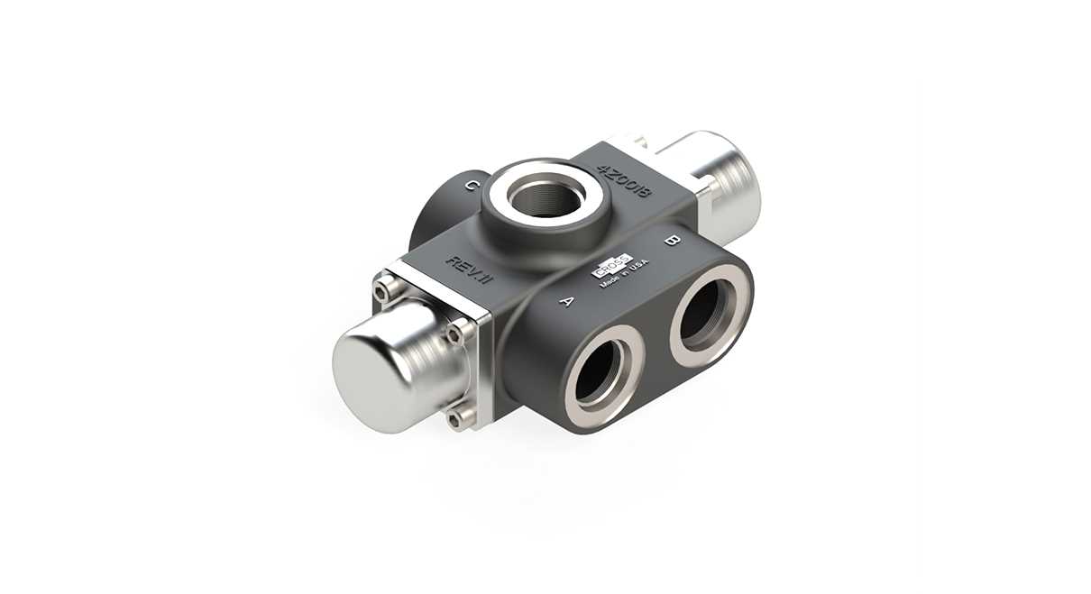
Flow management in fluid-powered systems is essential for ensuring optimal performance and efficiency. By adjusting the movement of fluid, these mechanisms allow for precise control of speed and force within machinery. Understanding how these controls operate is key to designing effective and reliable systems.
Main Types of Flow Control
- Manual regulation: Involves physical adjustment of flow channels to manage fluid speed. This method is often employed in simpler systems where automatic adjustments are unnecessary.
- Automatic regulation: Utilizes sensors and controllers to dynamically adjust flow rates. This ensures more consistent and responsive performance, particularly in complex operations.
Key Components Involved
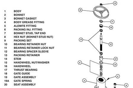
- Flow restrictors: These elements create a controlled reduction in fluid movement to maintain system balance and prevent overloading.
- Adjustable throttles:
Pressure Regulation Techniques in Valves
Effective pressure management is essential for ensuring the optimal performance of flow control devices. Proper regulation prevents excessive force buildup, which can cause damage to equipment or lead to inefficient operation. By employing various mechanisms, these systems maintain desired levels of control over the internal force, ensuring safety and reliability in fluid management processes.
Technique Description Spring-Loaded Mechanism Uses a calibrated spring to control internal Directional Control Valve Structure
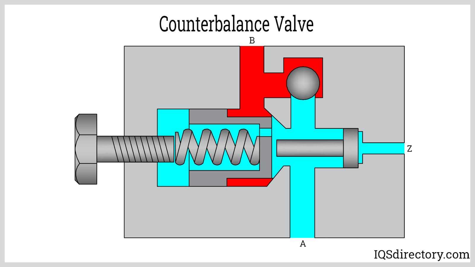
The directional control system is an essential component in regulating fluid movement within various mechanical setups. It manages the flow direction, allowing for smooth transitions and precise operation of machinery. Understanding its internal framework is crucial for identifying how each element interacts to control pressure and fluid paths effectively.
At the core of this system, various internal components work together to direct flow, including moving elements that shift positions to open or close passages. These elements interact with springs, spools, and chambers, ensuring consistent pressure regulation. The design of this control mechanism ensures that the system operates efficiently and responds to input changes with high accuracy.
Seals and Gaskets in Hydraulic Valves
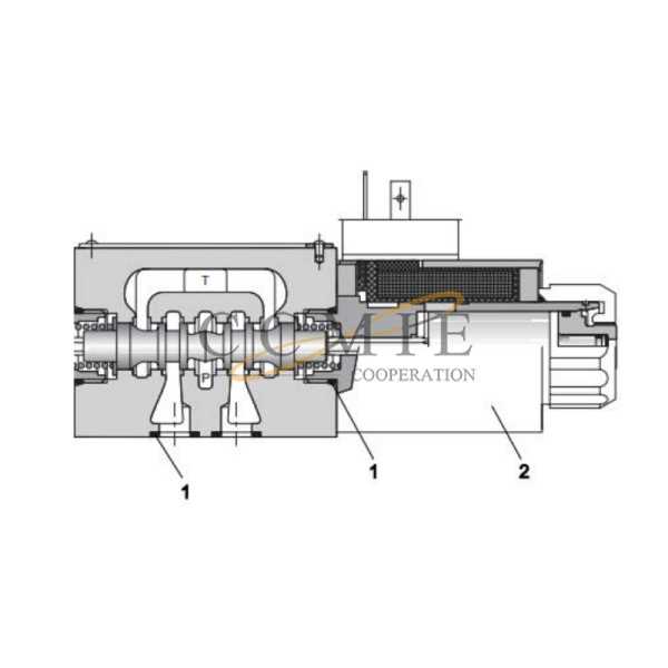
In various mechanical systems, components that ensure tightness and prevent leakage are crucial for maintaining efficiency and reliability. These elements play a vital role in sealing interfaces, safeguarding against contamination, and sustaining optimal performance during operation.
Types of Sealing Elements
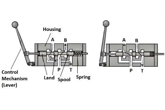
- O-rings: Commonly used due to their versatility and ease of installation.
- Flat gaskets: Provide a reliable barrier between flat surfaces, often made from materials like rubber or metal.
- Backup rings: Used in conjunction with O-rings to prevent extrusion and enhance durability.
Importance of Quality Materials
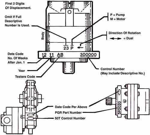
The selection of materials for these sealing components is essential. Factors such as temperature resistance, chemical compatibility, and wear resistance determine their effectiveness. High-quality materials help prevent premature failures, ensuring long-term reliability and performance of the entire system.
How Spool Valves Operate in Systems
Spool mechanisms play a crucial role in controlling the flow of fluid within various systems. They facilitate the regulation of pressure and movement, enabling precise operation of connected components. By directing the fluid through different channels, these mechanisms ensure that the system functions efficiently and meets operational demands.
When the spool is activated, it shifts positions, altering the path of the fluid. This movement creates an opening or blockage in specific routes, allowing for the precise management of the flow direction and pressure. As a result, the connected elements respond accordingly, executing tasks such as lifting, rotating, or pushing. The seamless coordination of the spool’s actions ensures that the entire system operates smoothly and effectively.
Maintenance of the spool mechanism is essential for optimal performance. Regular inspections help identify any wear or malfunction that could disrupt fluid flow. By ensuring that the spool operates correctly, systems can maintain their reliability and efficiency over time, reducing the risk of costly downtime or repairs.
Relief Valve Placement and Purpose
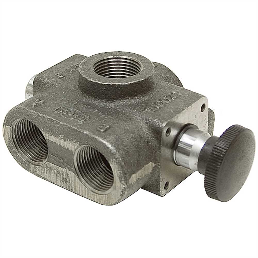
Understanding the positioning and function of a specific device is crucial for ensuring the efficiency and safety of any fluid control system. Proper placement enhances the overall performance and reliability of the mechanism, allowing for effective pressure management.
The main objectives of this component include:
- Preventing excess pressure buildup that could lead to system failure.
- Maintaining optimal operating conditions by allowing excess fluid to escape.
- Protecting other components from potential damage caused by high pressure.
Placement considerations typically involve:
- Locating it close to the source of pressure generation for quick response.
- Ensuring accessibility for maintenance and inspection purposes.
- Positioning it in a way that minimizes the risk of fluid leakage or contamination.
In summary, the strategic installation of this element plays a vital role in maintaining the integrity and functionality of the entire fluid system.
Actuators and Their Role in Valves
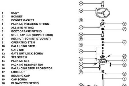
Actuators serve a vital function in the operation of control mechanisms, translating energy into motion to regulate the flow of various substances. They are essential components that facilitate the precise movement required for effective system management.
These devices can be categorized into different types, including electric, pneumatic, and hydraulic. Each type utilizes specific energy sources and mechanisms to perform their tasks, ensuring optimal performance across various applications. The choice of actuator directly influences the efficiency and responsiveness of the entire system.
In the context of regulation, actuators enable seamless control by responding to signals from monitoring systems. This responsiveness is crucial for maintaining desired conditions and preventing system failures. By adjusting the position of the controlling element, actuators contribute significantly to the overall functionality and safety of industrial operations.
Internal Channels for Fluid Flow
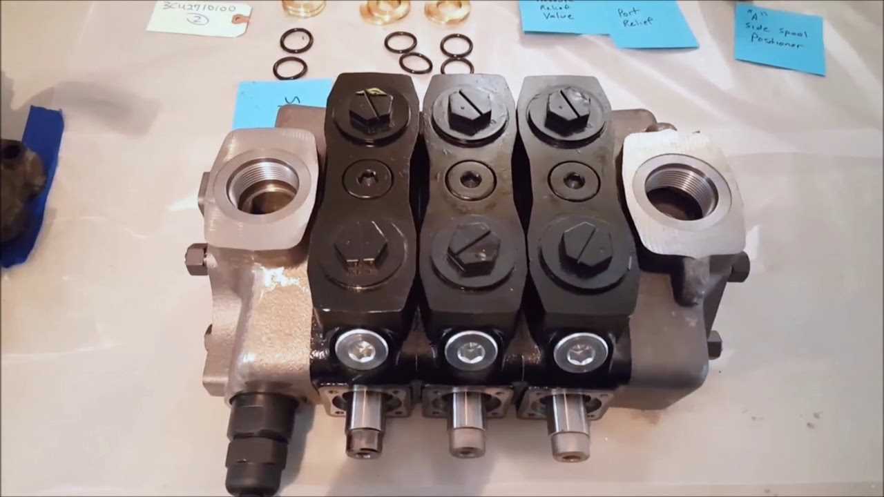
The design of internal pathways plays a crucial role in the movement of liquids within mechanical systems. These channels facilitate the controlled transmission of fluids, ensuring that the flow is efficient and effective. Properly engineered routes can significantly enhance performance and reliability in various applications.
Fluid dynamics within these pathways is essential for achieving desired outcomes. The configuration and dimensions of the channels impact factors such as pressure, velocity, and direction of the flow. Optimal channel design minimizes turbulence and energy loss, promoting smoother transitions and better overall functionality.
Additionally, the materials used in constructing these pathways must withstand the stresses of fluid movement. Corrosion resistance and durability are critical for maintaining integrity over time, especially in challenging environments. As technology evolves, advancements in manufacturing processes and materials continue to improve the effectiveness of these internal structures.
Importance of Pilot Operated Valves
In various fluid control systems, the role of certain mechanisms is crucial for effective operation. These devices allow for precise management of flow and pressure, enhancing overall system performance. Their functionality not only ensures reliability but also improves efficiency in diverse applications.
Benefits of Utilizing These Mechanisms
- Enhanced Control: They provide superior control over flow rates, allowing for more accurate adjustments in response to system demands.
- Increased Efficiency: These mechanisms minimize energy consumption by optimizing operational parameters, leading to cost savings.
- Improved Safety: Their design helps to prevent malfunctions and reduces the risk of system failures, ensuring a safer environment.
Applications in Various Industries
- Agriculture: Used in irrigation systems for effective water management.
- Manufacturing: Essential for automated processes that require precise fluid control.
- Construction: Utilized in heavy machinery to enhance operational efficiency.
Maintenance Tips for Valve Components
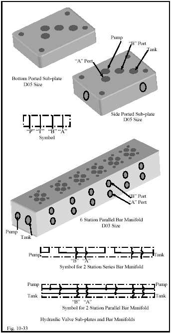
Regular upkeep of flow control mechanisms is essential to ensure optimal performance and longevity. Implementing a few simple practices can significantly reduce the risk of malfunction and enhance the efficiency of these critical components.
First, always keep the mechanism clean and free from debris. Accumulation of dirt or foreign materials can obstruct movement, leading to potential failures. Use appropriate cleaning agents that are compatible with the materials involved.
Second, conduct routine inspections for signs of wear or damage. Look for leaks, cracks, or unusual wear patterns that may indicate the need for replacement or repairs. Early detection can prevent more extensive issues down the line.
Additionally, lubricating moving parts as recommended by the manufacturer will help reduce friction and prevent premature wear. Ensure that the lubricant used is suitable for the specific type of mechanism to maintain its functionality.
Finally, maintain a proper operating environment. Extreme temperatures and humidity can adversely affect the performance of flow control devices. Keeping them within the recommended conditions will help preserve their integrity and functionality.