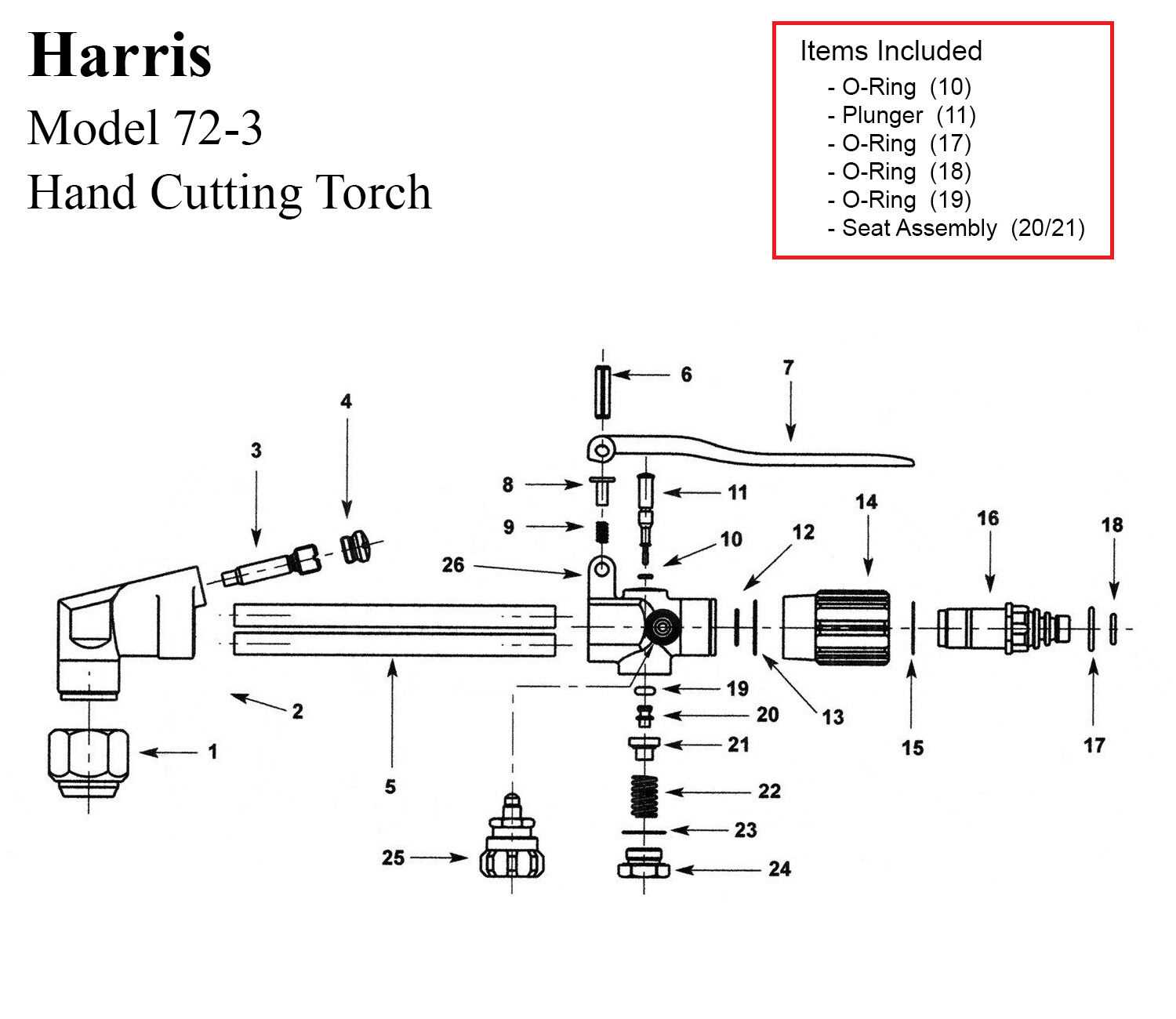
The functionality of a thermal cutting device relies on a variety of integral elements working in harmony. Each component plays a crucial role in ensuring the efficiency and precision of the operation. Gaining insight into these individual segments enhances the user’s ability to maintain and troubleshoot the equipment effectively.
By familiarizing oneself with the arrangement and purpose of these essential components, operators can improve their skills and ensure optimal performance. This knowledge is vital not only for effective usage but also for identifying potential issues that may arise during operation.
In this section, we will explore the various sections of the tool, delving into their specific functions and interactions. Understanding these relationships is key to mastering the art of precise thermal manipulation, paving the way for successful outcomes in various applications.
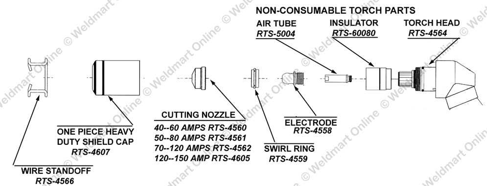
This section will delve into the essential elements that make up a specific tool used in metalworking and fabrication. By breaking down the fundamental components, readers will gain a clearer understanding of how these elements work together to achieve efficient results. Each part plays a crucial role in the overall functionality of the apparatus, contributing to its effectiveness in various applications.
1. Overview of Key Elements
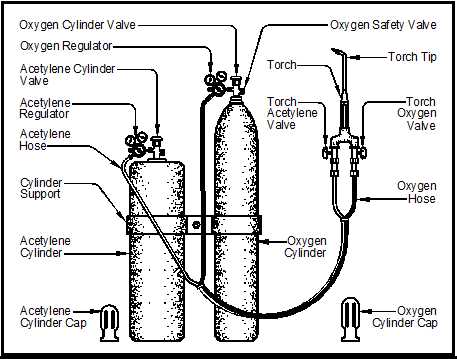
This subsection will provide a brief introduction to the significant elements found within the device, highlighting their importance in operation.
2. Fuel Supply Mechanism
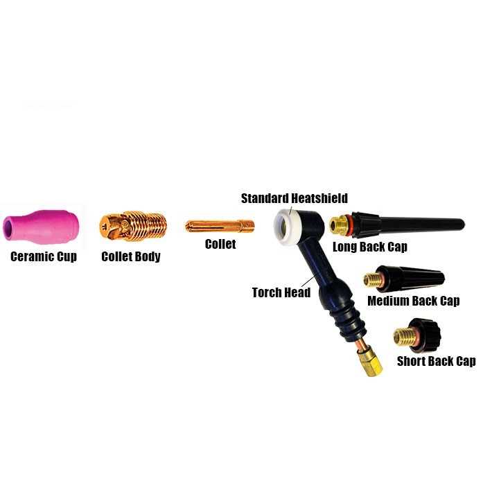
The system responsible for delivering the necessary fuel will be examined, detailing how it impacts performance and efficiency.
3. Oxygen Delivery System
Exploration of the oxygen pathway, explaining its critical function in the combustion process.
4. Mixing Chamber Role
A discussion on how the mixing chamber facilitates the correct ratio of fuel and oxygen for optimal operation.
5. Nozzle Functionality
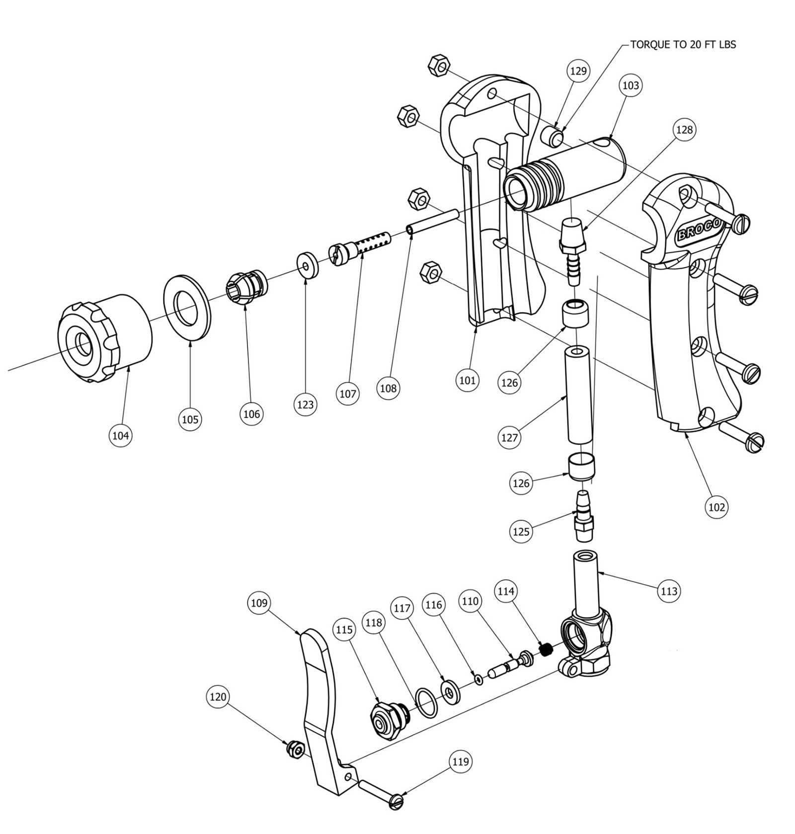
This section will analyze the nozzle’s design and its influence on the quality and precision of the cut.
6. Regulator Importance

An overview of the regulator’s role in controlling pressure levels, ensuring safe and effective usage.
7. Safety Features
A review of the built-in safety mechanisms that protect the user during operation.
8. Maintenance Considerations
Guidelines on maintaining the device to ensure longevity and reliability over time.
9. Common Issues and Solutions
A summary of frequent problems encountered during usage and practical solutions for troubleshooting.
10. Conclusion and Best Practices
Final thoughts on utilizing the tool effectively, emphasizing best practices for users.
| Component | Function |
|---|---|
| Fuel Supply Mechanism | Delivers necessary fuel for operation. |
| Oxygen Delivery System | Provides oxygen needed for combustion. |
| Mixing Chamber | Mixes fuel and oxygen for efficient burning. |
| Nozzle | Shapes and directs the flame for cutting. |
| Regulator | Controls pressure levels for safety. |
Types of Cutting Torches Available
In the realm of thermal severing tools, various designs cater to diverse applications and user preferences. Each variant offers unique features tailored for specific tasks, enhancing efficiency and precision in metal processing. Understanding the different options available can significantly impact workflow and productivity.
Popular Variants
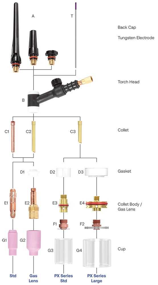
The market presents an array of models, each designed for particular functionalities and environments. Some are suited for heavy industrial use, while others excel in light-duty operations. Below is a summary of the most common types:
| Type | Description | Applications |
|---|---|---|
| Oxy-Acetylene | Utilizes a mixture of oxygen and acetylene for high-temperature cutting. | Heavy industrial fabrication, metalworking, and repair work. |
| Plasma | Employs ionized gas to achieve extreme heat, allowing for rapid severing. | Thin materials, intricate designs, and high-speed cutting tasks. |
| Propane | Uses propane as a fuel source, providing a cost-effective option. | Light-duty tasks, maintenance, and home workshops. |
Choosing the Right Tool
Selecting the appropriate severing implement hinges on various factors, including the material type, thickness, and the desired cutting speed. By evaluating specific requirements, users can optimize their choice, ensuring effective and safe operation.
Function of Each Part Explained
This section delves into the roles played by various components within a gas-operated cutting device. Understanding these functionalities enhances the efficiency and effectiveness of the tool, ensuring optimal performance during operations.
Key Component Functions
Regulator: This element controls the flow of gas, maintaining consistent pressure for a steady flame. Proper adjustment of the regulator is essential for achieving the desired temperature and cutting capability.
Ignition System
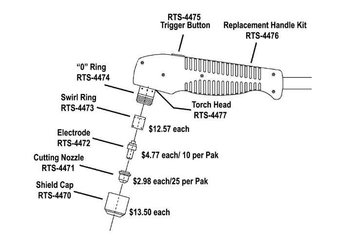
Igniter: The igniter initiates the combustion process, producing the flame needed for cutting through materials. Its reliability is crucial, as a faulty igniter can disrupt the operation and lead to inefficiencies.
Safety Features of Cutting Equipment
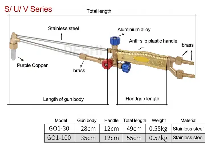
Ensuring the well-being of operators is paramount when working with thermal devices. Various mechanisms and designs are implemented to minimize risks associated with their use. These safety measures aim to protect users from potential hazards, enhancing overall operational security.
Key elements contributing to safe operation include:
| Feature | Description |
|---|---|
| Automatic Shut-off | This function halts operation when the device is not in use, preventing accidental ignition and conserving energy. |
| Flame Control | Adjustable settings allow users to control the intensity of the flame, reducing the risk of unintended ignition and material damage. |
| Protective Gear Compatibility | Designs accommodate the use of protective clothing and gear, ensuring operators remain safeguarded from heat and sparks. |
| Pressure Relief Valves | These valves release excess pressure, preventing equipment failure and potential explosions during operation. |
Implementing these safety features is essential for maintaining a secure working environment, enabling operators to perform tasks confidently and effectively.
Common Materials Used in Construction
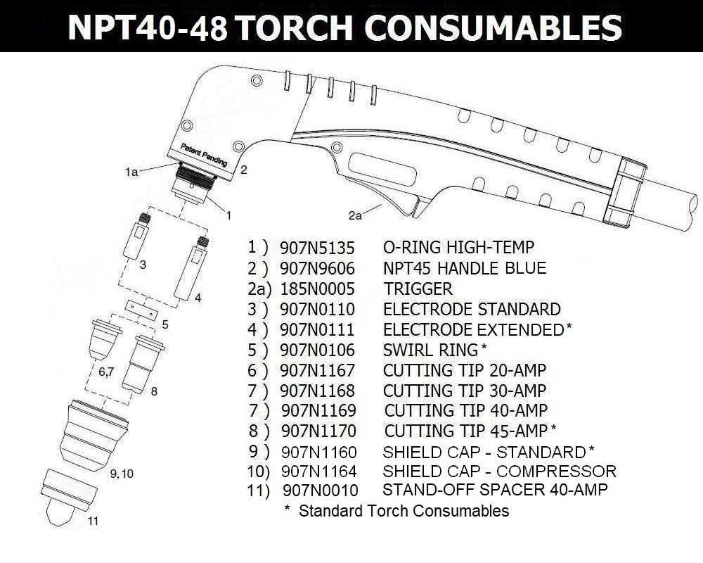
In various industries, the selection of materials plays a crucial role in ensuring the integrity and functionality of structures. Different materials are chosen based on their properties, applications, and the specific requirements of the project at hand. Understanding these materials can greatly enhance the quality and efficiency of construction efforts.
Metals and Alloys
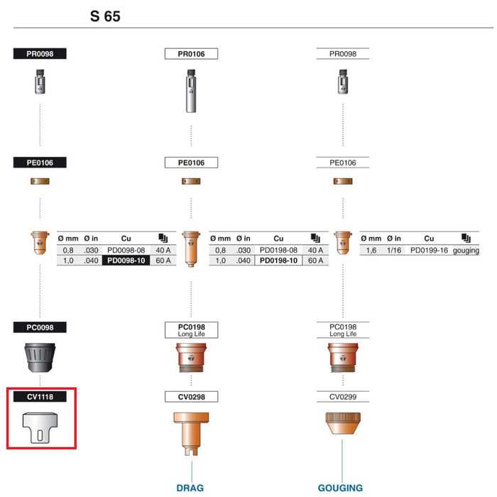
Metals are among the most widely utilized materials in construction due to their strength, durability, and versatility. Commonly used metals include steel, known for its high tensile strength, and aluminum, favored for its lightweight characteristics. These materials are essential in creating frameworks, reinforcements, and various structural components.
Composite Materials
Composite materials combine two or more substances to achieve enhanced properties. For instance, fiber-reinforced polymers offer excellent strength-to-weight ratios and resistance to corrosion, making them ideal for a range of applications. These materials are increasingly popular in modern construction for their ability to provide both performance and aesthetic value.
Maintenance Tips for Longevity
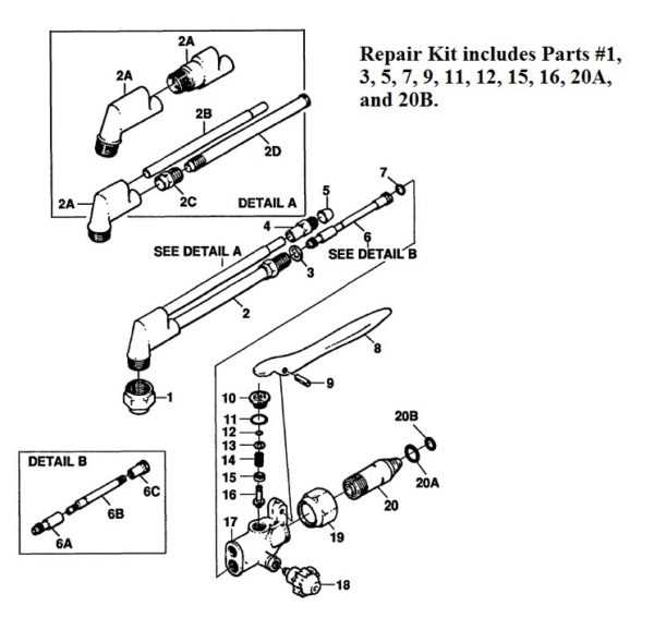
Ensuring the durability and efficiency of your equipment requires regular care and attention. Implementing simple maintenance practices can significantly extend the lifespan of your tools while enhancing their performance. Below are some essential tips to help you maintain your apparatus effectively.
Regular Cleaning
Cleaning your equipment after each use prevents the buildup of debris and contaminants that can affect performance. Follow these steps:
- Use a soft brush or cloth to remove residue.
- Wipe down surfaces with a suitable cleaner.
- Inspect for any signs of wear or damage.
Routine Inspections
Conducting periodic checks allows you to identify potential issues before they escalate. Consider the following:
- Examine connections and fittings for tightness.
- Look for cracks or corrosion on surfaces.
- Test functionality to ensure optimal operation.
Identifying Wear and Tear Signs
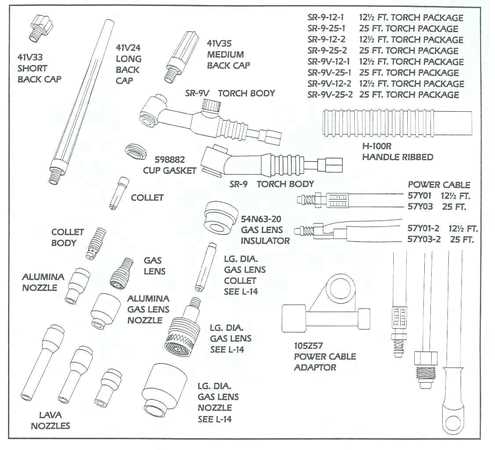
Recognizing indicators of deterioration is crucial for maintaining the efficiency and safety of your equipment. Regular inspection helps ensure optimal functionality and prevents unexpected failures that could lead to costly repairs or hazardous situations. Understanding common symptoms of wear can guide you in timely replacements or maintenance actions.
Common Indicators of Damage
Several visible signs can indicate wear and tear on your equipment. Look for cracks, deformation, or any unusual discoloration that may suggest overheating or excessive use. Additionally, components may exhibit looseness or abnormal movement, which can compromise overall performance.
Maintaining Equipment Longevity
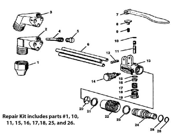
To prolong the lifespan of your tools, perform routine checks for wear. Clean components regularly and ensure proper storage to minimize exposure to elements that could accelerate degradation. Promptly addressing minor issues can prevent them from escalating into significant problems.
Upgrading Components for Better Performance
Enhancing the elements of your tool can significantly improve its efficiency and effectiveness. By selecting higher-quality or more suitable components, users can experience greater precision and durability in their tasks. This section will explore various options available for upgrading.
Consider the following components that can be optimized:
- Regulators: Upgrading to a more efficient regulator can help maintain a stable flow, leading to better control.
- Hoses: High-grade hoses reduce wear and enhance the flow of gas, ensuring a reliable performance.
- Nozzles: Switching to specialized nozzles allows for better versatility and adaptability in various applications.
Implementing these upgrades can result in:
- Increased operational efficiency
- Improved safety measures
- Enhanced longevity of the equipment
Evaluating and upgrading these elements not only maximizes performance but also contributes to overall user satisfaction.