
Understanding the intricate relationships and configurations of various elements within a system can be crucial for maintenance, troubleshooting, and upgrades. By studying the layout of individual units and their connections, users can gain valuable insights into the functionality and alignment of mechanical or electrical setups.
Exploring visual representations of assembly structures allows for a clearer understanding of how different segments interact. Whether you’re dealing with mechanical systems or more complex setups, breaking down the connections between different components can provide clarity and facilitate smoother operations.
In many cases, the arrangement of individual units reveals not only their positions but also the specific roles they play within a larger mechanism. Analyzing these configurations helps to optimize processes and ensure that each element is functioning as intended, contributing to the overal
Understanding Equipment Components
In many machines and tools, understanding the individual components is essential for efficient operation and maintenance. These elements work together to ensure the smooth functioning of the whole system, each playing a critical role in the overall process. Knowing the structure and role of each component can help with repairs, upgrades, and optimal use.
- Core Elements: These are the central units that handle the primary functions of the system.
- Supportive Units: Secondary elements provide stability and enhance the performance of core units.
- Connecting Components: These parts link different units, ensuring communication and movement between sections.
- Physical size and shape
- Color coding of different elements
- Labeling or numbering present on the items
How to Identify Key Delta Parts
Understanding the essential components of a system is crucial for efficient operation and maintenance. Recognizing the significant elements can aid in troubleshooting, replacement, and overall functionality enhancement. This guide will outline methods to help you effectively identify these crucial components.
Visual Inspection Techniques
Begin by examining the unit visually. This initial step can provide insights into the arrangement and condition of the components. Pay attention to:
Utilizing Reference Materials
Employing available reference materials can significantly facilitate identification. Resources may include:
- User manuals that provide illustrations and descriptions
- Online forums where experts share insights and images
- Manufacturer websites that offer detailed breakdowns of components
Common Issues with Delta Diagrams
In various fields, visual representations can often lead to misunderstandings or misinterpretations. Such graphical illustrations, designed to clarify complex systems or components, sometimes encounter recurring challenges that can hinder effective communication.
Misinterpretation of Symbols
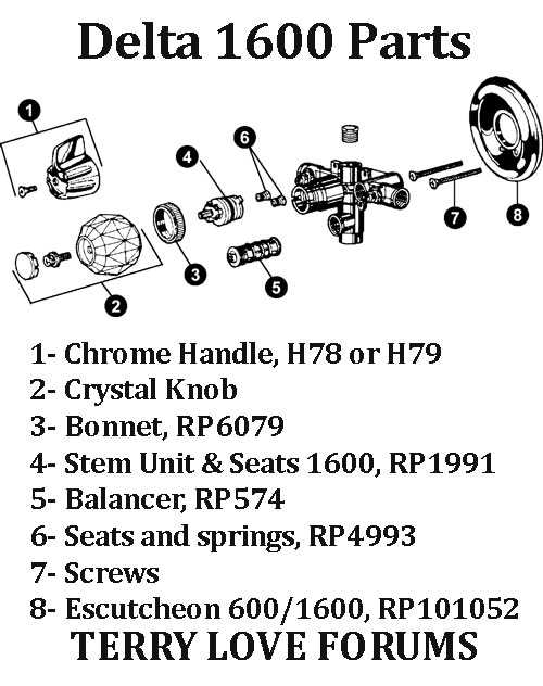
One prevalent problem arises from the ambiguity of symbols used in these visuals. Different interpretations can stem from varying backgrounds or experiences of the users, resulting in confusion regarding the intended message. Ensuring clarity in symbol usage is essential to minimize such discrepancies.
Inaccurate Connections
Another frequent issue involves the accuracy of connections depicted between elements. Misleading lines or arrows may suggest relationships that do not exist or obscure actual connections, leading to flawed analysis or conclusions. It is crucial to verify that all links are correctly represented to maintain the integrity of the information conveyed.
Locating Delta Parts on a Diagram
Understanding the arrangement of components within a schematic is essential for effective analysis and troubleshooting. By familiarizing oneself with the layout and symbols used, one can efficiently identify various elements necessary for maintenance or replacement tasks.
Common Symbols and Indicators
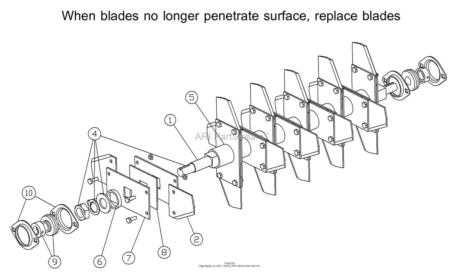
Many illustrations utilize standardized symbols to represent different components. Here are some frequently encountered indicators:
- Circle: Often denotes a connection point.
- Square: Typically represents a device or unit.
- Arrow: Indicates the direction of flow or movement.
Steps for Effective Identification
To successfully locate elements within the schematic, follow these guidelines:
- Start by reviewing the legend or key that explains the symbols used.
- Trace connections to understand how different units interact.
- Use a highlighter to mark identified components for easier reference.
Interpreting Symbols in Delta Schematics
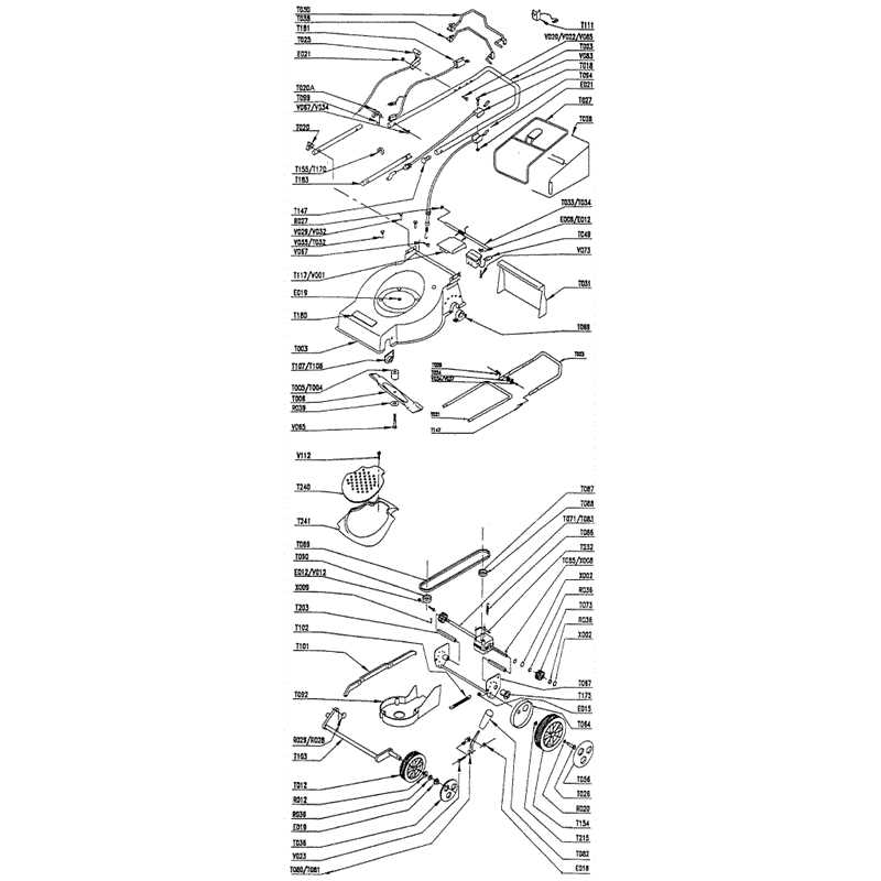
Understanding the visual language used in technical illustrations is essential for effective analysis and maintenance. Each symbol represents specific components or functions, forming a comprehensive picture of the system’s operation. Grasping these representations allows individuals to navigate the complexities of the design with confidence.
Commonly Used Symbols
Here are some frequently encountered icons and their meanings:
- Resistor: Indicates resistance in the circuit.
- Capacitor: Represents energy storage capacity.
- Inductor: Denotes coil-like components that store energy in a magnetic field.
- Ground: Symbolizes the reference point for the electrical potential.
Reading the Layout
When interpreting these visuals, consider the following guidelines:
- Start by identifying the main components highlighted by distinct symbols.
- Follow the connections represented by lines, which indicate how different elements interact.
- Note any annotations that provide additional details or specifications.
By familiarizing yourself with these symbols and their meanings, you enhance your ability to troubleshoot and innovate effectively.
Tools for Reading Delta Diagrams
Understanding intricate schematics requires the right set of tools to interpret and analyze information effectively. These instruments not only aid in comprehending complex visuals but also facilitate efficient troubleshooting and maintenance. A clear grasp of the components and their interconnections is essential for anyone working with technical illustrations.
Among the primary instruments, high-quality magnifying glasses play a vital role in examining fine details, ensuring that every element is visible. Additionally, digital tablets and software applications allow for zooming in and annotating directly on the representations, enhancing the overall experience. Furthermore, printed reference materials can serve as helpful guides, providing context and explanations for various elements encountered.
Finally, collaboration with colleagues and industry experts can yield insights that deepen understanding. Engaging in discussions and sharing perspectives can uncover nuances that one might overlook while working alone. Utilizing these diverse tools and resources ensures a comprehensive approach to interpreting intricate visuals.
Delta Model-Specific Diagram Differences
In the realm of model specifications, understanding variations between visual representations is crucial for effective analysis and application. These representations often highlight distinct features and components that are tailored to each specific model. By recognizing these differences, users can better navigate the complexities associated with each configuration.
Variability in Component Layout
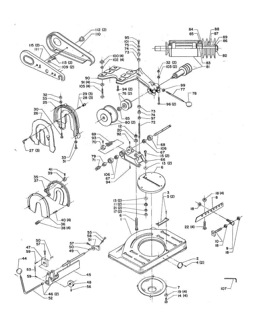
The arrangement of elements can vary significantly among different models. This variability can impact both functionality and maintenance. Key factors include:
- Positioning of essential components
- Accessibility of parts for servicing
- Integration of advanced technologies
Distinct Symbol Usage
Another important aspect is the unique symbols utilized in various representations. Each model may adopt specific notations to convey information more effectively. Notable distinctions include:
- Specific icons for different functions
- Color coding to indicate operational status
- Standardized markings for user guidance
Updating Your Delta Parts Catalog
Maintaining an accurate and comprehensive inventory of components is crucial for efficient operations. Regular updates ensure that all essential elements are readily available, enhancing performance and minimizing downtime.
To effectively refresh your collection of items, consider the following steps:
- Assess Current Inventory: Review existing components to identify what needs updating.
- Research New Offerings: Explore the latest innovations and replacements that can enhance your operations.
- Organize Information: Arrange the details systematically for easy access and reference.
- Implement Changes: Update records to reflect the most current options available.
- Train Staff: Ensure that team members are familiar with the updated listings and know how to access them.
By following these guidelines, you can ensure your collection remains current and efficient, ultimately leading to improved workflow and productivity.
Benefits of Using Delta Parts Diagrams
Utilizing schematic representations offers numerous advantages for understanding complex systems and components. These visual tools enhance clarity, facilitate communication, and streamline processes, making them invaluable in various fields, including engineering and manufacturing.
Improved Understanding
One significant advantage is the enhanced comprehension of intricate setups. By providing a visual layout, users can quickly grasp the relationships between different elements. This understanding leads to:
- Faster learning curves for new users
- Increased retention of information
- Reduced chances of errors during assembly or maintenance
Efficient Troubleshooting
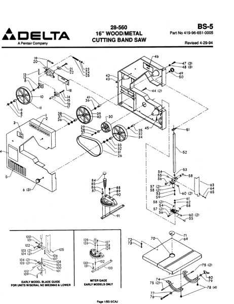
Schematic representations also play a crucial role in troubleshooting. When issues arise, these visual aids allow technicians to:
- Identify potential problem areas quickly
- Trace connections and interactions between components
- Implement solutions more effectively
How to Order Delta Replacement Parts
Ordering components for your devices can be a straightforward process when you know the right steps to follow. Whether you need to replace a worn-out element or upgrade to a newer model, understanding the ordering procedure will ensure a smooth experience.
Identify the Required Component: Before placing an order, it’s essential to pinpoint the specific item you need. Refer to your product’s user guide or online resources to determine the correct identifier, which may include a model number or description.
Visit the Authorized Retailer: Once you have the necessary information, head to a trusted retailer that specializes in your device’s brand. These retailers typically have access to a wide range of options and can assist you in finding the exact item.
Check Availability: Before finalizing your order, confirm that the desired item is in stock. Many retailers provide online inventory checks, saving you time and ensuring the product you need is readily available.
Place Your Order: After confirming availability, you can proceed with your purchase either online or in-store. Ensure you have all relevant details ready, including payment information and shipping address if applicable.
Follow Up: After placing your order, keep an eye on shipping updates. If you encounter any issues or delays, don’t hesitate to reach out to customer service for assistance.
Troubleshooting with Delta Schematics

When faced with technical difficulties, utilizing schematics can significantly streamline the diagnostic process. These visual representations serve as valuable resources for identifying issues and understanding the relationships between various components.
Identifying Common Issues
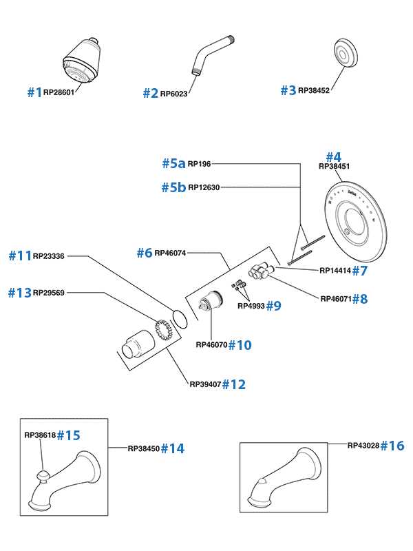
Understanding typical problems can expedite repairs. Below are some common issues encountered:
- Inconsistent performance
- Unexpected shutdowns
- Unusual noises during operation
Steps for Effective Troubleshooting
Follow these guidelines to efficiently address issues:
- Review the schematic to locate relevant components.
- Check connections and ensure they are secure.
- Test components individually to isolate the problem.
- Consult the manual for specific troubleshooting advice.
- Replace any faulty components as identified.
By following these steps and leveraging schematics, resolving technical issues becomes a more manageable task, enhancing overall efficiency.
Customizing Diagrams for Delta Machinery
Adapting visual representations for specific equipment enhances understanding and usability. By tailoring illustrations to fit individual requirements, users can improve their experience and streamline operations. This section will explore effective strategies for personalizing schematics related to machinery.
- Identify Key Components: Begin by recognizing the essential elements that require emphasis in your illustrations.
- Utilize Color Coding: Implement distinct colors to differentiate various parts, facilitating quick identification and comprehension.
- Add Annotations: Supplement visuals with informative notes to clarify functions and features.
- Integrate User Feedback: Encourage input from operators to ensure that modifications meet practical needs and enhance usability.
- Regular Updates: Keep illustrations current by revising them in accordance with any design or functional changes in the machinery.
By following these guidelines, individuals can create customized illustrations that serve not only as functional tools but also as educational resources for effective machinery operation.