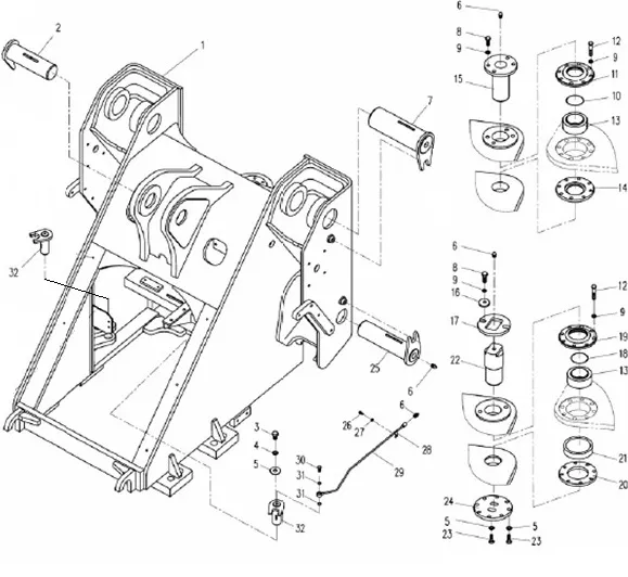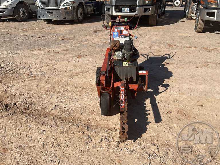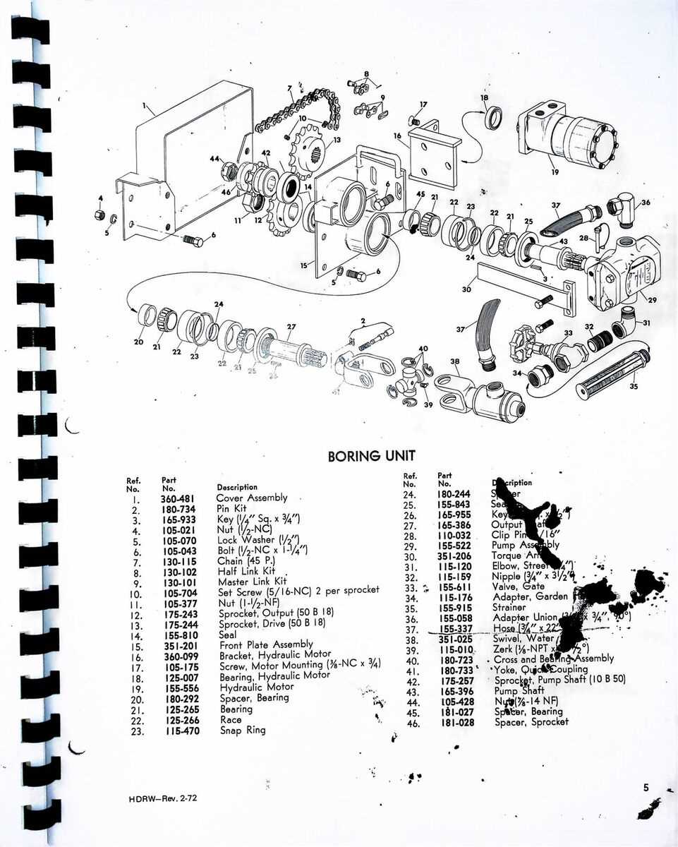
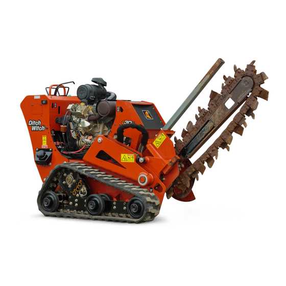
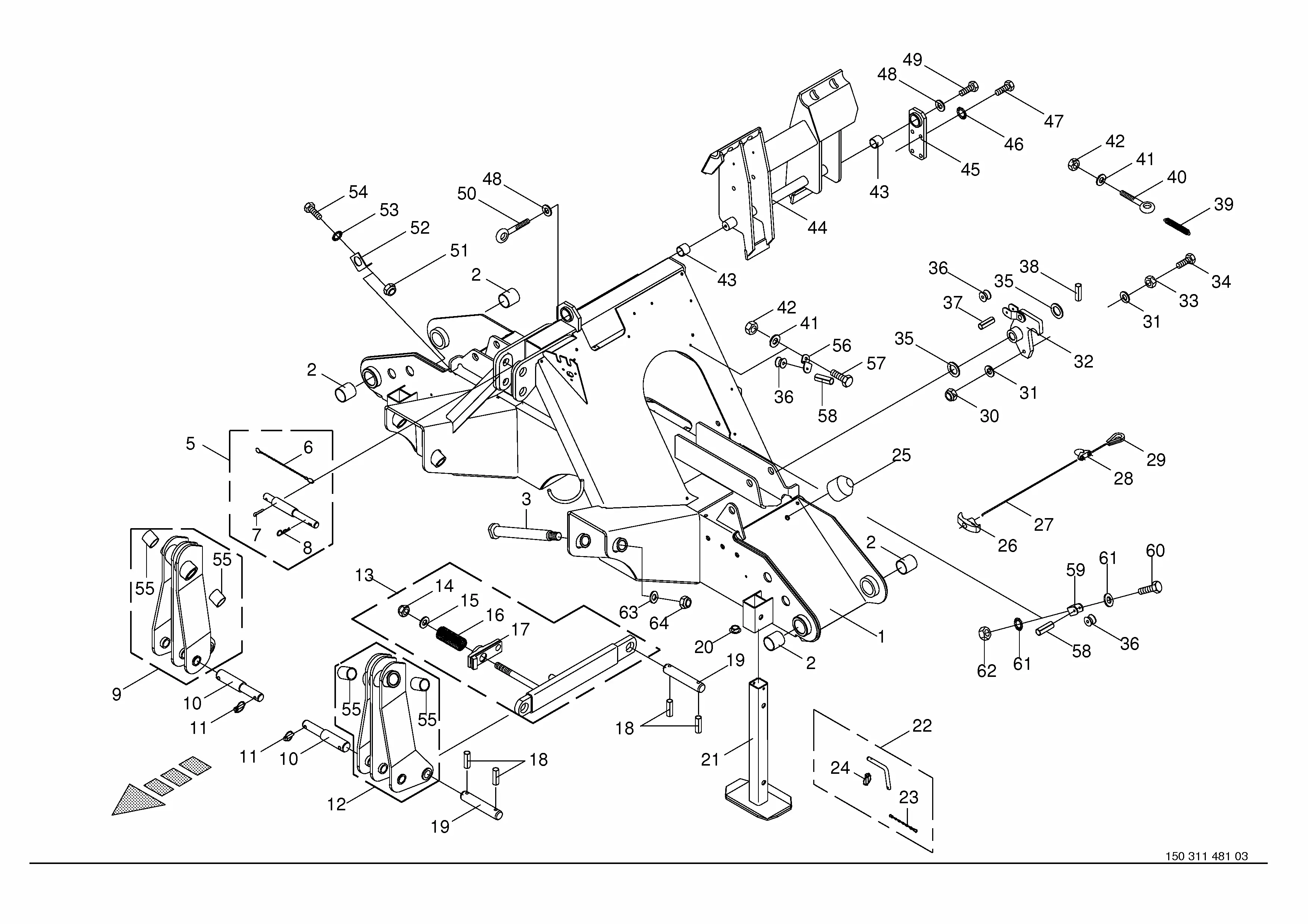
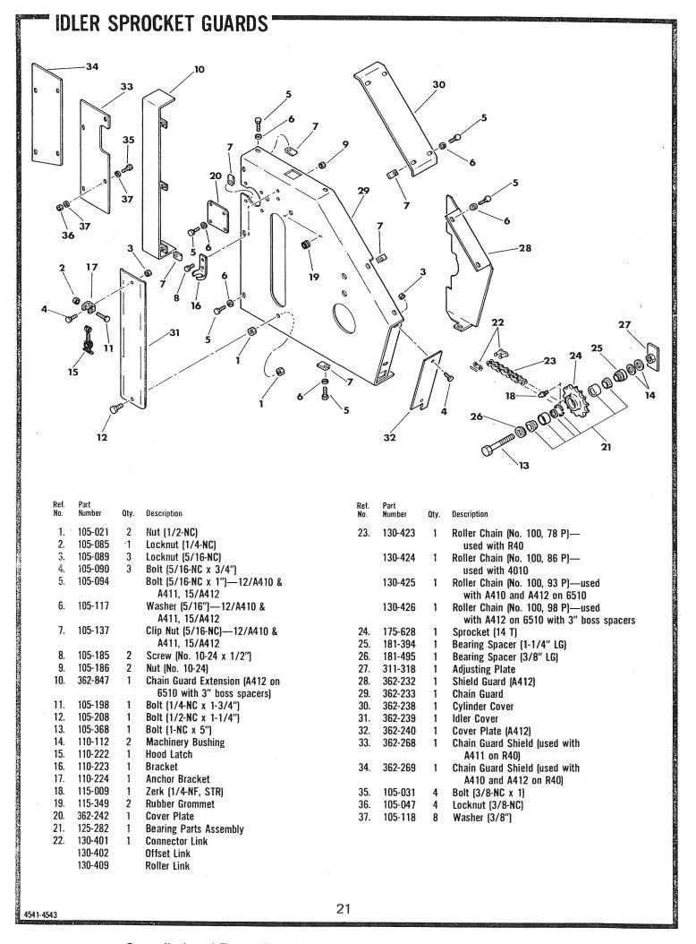
ditch witch 1030 parts diagram

When it comes to maintaining machinery, one of the key aspects is having a clear and accurate understanding of the internal setup. This knowledge ensures that repairs and replacements are carried out with precision, preventing further issues down the line. A detailed breakdown of individual elements plays a crucial role in streamlining this process, offering a roadmap for effective servicing.

Accurate schematics allow technicians to visualize each element in relation to the whole structure. This helps identify potential wear points and facilitates smoother replacements. By understanding how each component interacts with others, the overall longevity and performance of the equipment can be significantly enhanced.

Components Overview

This section provides a detailed insight into the main mechanical elements and functional units of the equipment. Understanding these components ensures effective use, maintenance, and troubleshooting, helping to keep the machinery in optimal working condition.

Key Mechanical Units
ditch witch 1030 parts diagram

  • Engine Assembly – Powers the equipment and drives various mechanisms.
  • Transmission System – Transfers power from the engine to the working parts, ensuring smooth operation.
  • Hydraulic Components – Controls the movement and functionality of various arms and attachments.

Additional Functional Elements
ditch witch 1030 parts diagram

  1. Control Panel – Allows the operator to manage speed, direction, and other operational parameters.
  2. Safety Mechanisms – Includes systems to ensure operator protection and prevent malfunctions.
  3. Attachment Points – Connects additional tools or components, enhancing versatility.

Key Features of Ditch Witch 1030

This equipment is designed for efficient and reliable performance in challenging environments. It is well-known for its versatility, durability, and ability to tackle various ground conditions, making it a valuable tool for different types of projects.

Efficient Performance
ditch witch 1030 parts diagram

The machine delivers exceptional efficiency, allowing operators to complete tasks quickly and with minimal effort. Its powerful engine and optimized design ensure smooth operation, even in demanding conditions.

Durable Construction
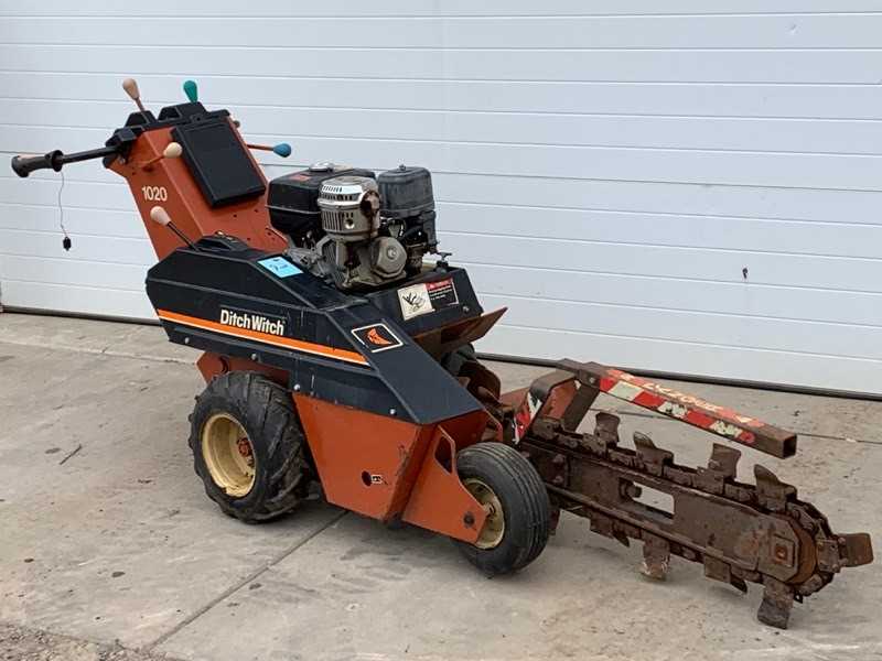
ditch witch 1030 parts diagram

Built with high-quality materials, the device offers long-lasting durability. Its robust construction enables it to withstand harsh environments, ensuring consistent performance over time. Reliability is one of its standout characteristics, making it a go-to option for professionals seeking long-term value.

Understanding the Function of Engine Parts

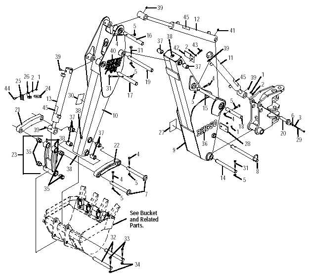
The core of any mechanical system is its engine, a complex assembly of components that work together to convert energy into motion. Each element of the engine has a specific role, ensuring smooth performance and optimal efficiency. Comprehending how these components interact helps in maintaining and troubleshooting the engine effectively.

Main Components and Their Roles

  • Pistons: These are responsible for transferring the force generated by combustion to the crankshaft, enabling movement.
  • Crankshaft: This key component converts the linear motion of the pistons into rotational movement, driving the machinery.
  • Valves: They control the flow of air and fuel into the engine and allow exhaust gases to exit after combustion.

Combustion Process and Its Importance
ditch witch 1030 parts diagram

At the

Blade Mechanism and Maintenance Tips
ditch witch 1030 parts diagram

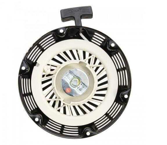
The cutting system plays a critical role in ensuring efficient performance. Keeping the blade assembly in proper condition not only enhances the overall function but also prolongs the lifespan of the equipment. Below are essential recommendations on how to maintain this mechanism effectively.

Key Components Overview

Understanding the individual parts of the blade assembly is crucial for smooth operation. The cutting edge, pivot points, and attachment hardware all require routine checks to prevent wear and damage. Make sure to inspect these areas frequently to ensure they are free from obstructions and securely fastened.

Maintenance Guidelines

Regular maintenance is key to ensuring longevity. Clean the blade and its surrounding components after each use, removing dirt and debris that could hinder performance. Additionally, sharpen the blade as needed and lubricate all moving parts. Always tighten any loose connections to avoid malfunctions during operation.

Pro Tip:

Hydraulic System Components Explained
ditch witch 1030 parts diagram

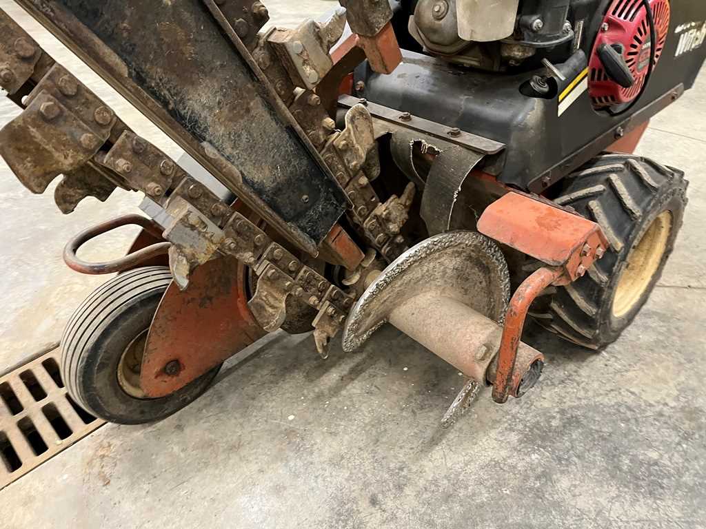
The hydraulic system plays a crucial role in ensuring efficient operation by utilizing pressurized fluid to transfer power. Understanding the key components involved in this system is essential for maintaining optimal performance and addressing any potential issues. Below, we break down the main elements that make up a standard hydraulic mechanism.

Electrical Wiring and Diagram Insights

ditch witch 1030 parts diagram

Understanding the electrical layout and wiring configurations is crucial for maintaining and troubleshooting equipment effectively. This section delves into the intricacies of electrical connections, highlighting key components and their functionalities. A well-organized schematic can significantly aid in the diagnosis of issues, ensuring optimal performance and longevity of machinery.

Key Components and Their Functions

ditch witch 1030 parts diagram

Every system comprises essential elements, each playing a pivotal role in the overall operation. Connectors, switches, and fuses are fundamental parts that facilitate electrical flow. Knowledge of these components helps users comprehend how energy is directed and managed within the system.

Interpreting Electrical Schematics

ditch witch 1030 parts diagram

Reading electrical illustrations requires a foundational grasp of symbols and conventions used in schematics. Symbols represent various components, while lines indicate connections and pathways. Familiarity with these representations enables effective analysis and troubleshooting, making it easier to identify potential faults or areas for improvement.

Transmission Parts and Performance

The efficiency of a vehicle’s transmission system is crucial for optimal functionality and overall performance. Understanding the components involved in this system can significantly enhance operation, ensuring seamless power transfer and reliability during use. This section explores key elements contributing to the effectiveness of the transmission mechanism and their roles in enhancing vehicle capabilities.

Key Components

Among the essential components, the gearbox plays a vital role in adjusting speed and torque. Couplings facilitate smooth engagement and disengagement of the system, while the hydraulic system ensures that power is distributed effectively. Regular maintenance of these elements is necessary to avoid performance degradation.

Performance Optimization

Improving transmission efficiency can lead to better fuel economy and enhanced handling. Upgrading specific components, such as the clutch and fluid quality, can also yield significant benefits. Ensuring that all elements are in optimal condition is essential for achieving peak performance during operation.

Wear and Tear: Identifying Crucial Parts

Regular maintenance and observation are essential for any machinery to ensure optimal performance and longevity. Over time, specific components can experience deterioration, leading to reduced efficiency and potential breakdowns. Recognizing these vital elements and their signs of wear can help in timely interventions, thus avoiding costly repairs.

Common Signs of Deterioration

  • Increased noise levels during operation
  • Vibrations that were previously absent
  • Unusual leaks or fluid loss
  • Difficulty in movement or operation

Key Components to Monitor

  1. Hydraulic systems
  2. Drive belts
  3. Seals and gaskets
  4. Blades and cutting edges
  5. Electrical connections and wiring

By staying vigilant and regularly inspecting these critical components, operators can ensure the reliability and efficiency of their machinery, ultimately enhancing productivity and safety in operations.

Troubleshooting Common Component Issues

When working with heavy machinery, encountering problems with certain elements is not uncommon. Understanding the typical challenges that arise can significantly enhance the efficiency of repairs and maintenance. This section focuses on identifying and resolving frequent issues that may arise with various components of the equipment.

Identifying Symptoms of Malfunction

ditch witch 1030 parts diagram

Recognizing the signs of component failure is crucial for effective troubleshooting. Common symptoms include unusual noises, vibrations, or performance drops. Paying attention to these indicators can help pinpoint the problematic part, allowing for timely intervention and repair.

Steps for Effective Resolution

ditch witch 1030 parts diagram

Once a malfunction is identified, follow a systematic approach to address the issue. Start with visual inspections to detect any obvious wear or damage. Consult maintenance manuals for specific guidelines related to the component. Regular upkeep can prevent many issues, ensuring that the equipment operates smoothly over time.

Parts Replacement for Optimal Efficiency

ditch witch 1030 parts diagram

Ensuring that all components are functioning effectively is crucial for maintaining peak performance in any machinery. Regular updates and substitutions of essential elements can significantly enhance the overall productivity and longevity of the equipment. By focusing on timely replacements, operators can prevent breakdowns and minimize downtime.

Identifying worn or damaged elements is the first step toward maintaining efficiency. Conducting routine inspections allows users to pinpoint issues before they escalate. When specific components show signs of wear, replacing them promptly can help preserve the integrity of the machine and ensure it operates at its best.

Investing in high-quality replacements is equally important. Utilizing durable materials not only improves the functionality of the equipment but also reduces the frequency of future replacements. This proactive approach leads to improved reliability and sustained operational capacity.

In conclusion, prioritizing the replacement of key components enhances the performance and reliability of machinery. By adopting a systematic approach to maintenance, users can achieve optimal efficiency and extend the lifespan of their equipment.

Safety Features and Diagram Layout

This section explores the essential safety components and the structural organization of the visual representation related to the equipment. Understanding these elements is crucial for effective operation and maintenance, ensuring the safety of users and the longevity of the machinery.

Key Safety Mechanisms

ditch witch 1030 parts diagram

Various safety mechanisms are integrated into the system to minimize risks during operation. These include emergency shutdown features, protective barriers, and warning indicators that enhance user awareness. Regular inspections and adherence to safety protocols are vital to ensure these features function correctly.

Visual Representation Structure

ditch witch 1030 parts diagram

The layout of the visual representation provides a clear overview of the equipment’s components and their interconnections. It aids in troubleshooting and maintenance tasks, facilitating a better understanding of the operational flow.

Component Description
Pump This device is responsible for converting mechanical energy into hydraulic energy by pressurizing the fluid, initiating the power flow.
Hydraulic Cylinders These are used to convert hydraulic energy back into mechanical force, providing the necessary movement or lifting actions.
Valves Valves regulate the flow and pressure within the system, controlling how and when hydraulic fluid moves through the circuit.
Reservoir
Feature Description
Emergency Shutdown Instantly stops all operations in case of an emergency.
Protective Barriers Physical shields that prevent accidental contact with moving parts.
Warning Indicators Visual alerts that signal potential hazards during operation.