Exploring the inner workings of mechanical tools can reveal a fascinating array of elements that come together to create functionality. Each element plays a crucial role, from delivering motion to maintaining stability. By examining how these elements are arranged, we gain insights into the craftsmanship behind reliable machinery.
Key elements within these devices contribute to various functions such as rotation, speed control, and safety measures. Recognizing their individual roles and placements can simplify maintenance and enhance operational efficiency. Knowing how different elements interact can also aid in troubleshooting, allowing for quick identification of issues.
Whether performing a repair or optimizing performance, understanding the complete structure of a power tool provides a clearer picture of its capabilities. This knowledge ensures more effective use and helps extend the equipment’s lifespan, ensuring consistent performance over time.
Drill Parts Diagram
Understanding the structure of a handheld power tool can help users maintain, repair, or upgrade their equipment more effectively. By exploring the various sections and mechanisms, one gains insight into how different elements work together to perform a task efficiently. This knowledge is essential for both beginners and experienced users aiming to enhance the tool’s performance or troubleshoot issues.
Key Components Overview

- Motor Assembly: The core that drives rotational movement, typically located in the central housing. It’s responsible for converting electrical energy into mechanical action.
- Chuck Mechanism: The adjustable holder that secures various attachments in place, allowing for a wide range of tasks. It often includes a ratcheting feature for better grip.
- Speed Control Trigger: A user-operated feature that regulates the intensity of the rotational force, enabling smoother or faster operation as needed.
- Grip Handle: Designed for comfort and stability, it reduces vibration impact and enhances control during use. Some models may include ergonomic padding.
Maintenance Tips
- Regularly inspect the tool for any signs of wear, especially around the central mechanism and connection points.
- Lubricate moving parts periodically to ensure smooth operation and extend the lifespan of individual components.
- Keep the attachment holder clean and free of debris to maintain a secure grip on different accessories.
Understanding Drill Components Layout
The arrangement of various elements in a handheld power tool determines its effectiveness and usability. Each section plays a specific role in the overall function, contributing to tasks such as creating holes, driving fasteners, or even sanding surfaces. The configuration is designed for optimal balance, ease of use, and maintenance.
Inside the housing, interconnected mechanisms transfer energy from the power source to the moving sections, converting it into rotational motion. These mechanisms are strategically positioned to provide the necessary torque while ensuring safety. The control interfaces, such as switches and grips, are ergonomically placed for intuitive handling.
Understanding the internal layout can enhance the ability to perform repairs, choose the right accessory, and maintain peak performance. Recognizing how individual sections connect and function together ensures proper handling, increases longevity, and prevents common issues.
Key Elements of a Drill

Understanding the main components of this versatile tool can help you maintain and use it more effectively. Each component plays a crucial role in ensuring smooth operation, precision, and power during various tasks.
Motor Assembly
The heart of the tool, the motor, converts electrical energy into mechanical motion, providing the necessary force for driving tasks. Its efficiency and power output determine the tool’s performance across different materials and conditions.
Chuck Mechanism
At the front, the chuck is responsible for securing different accessories, such as cutting or driving attachments. Its adjustable design accommodates various sizes, offering versatility for multiple applications.
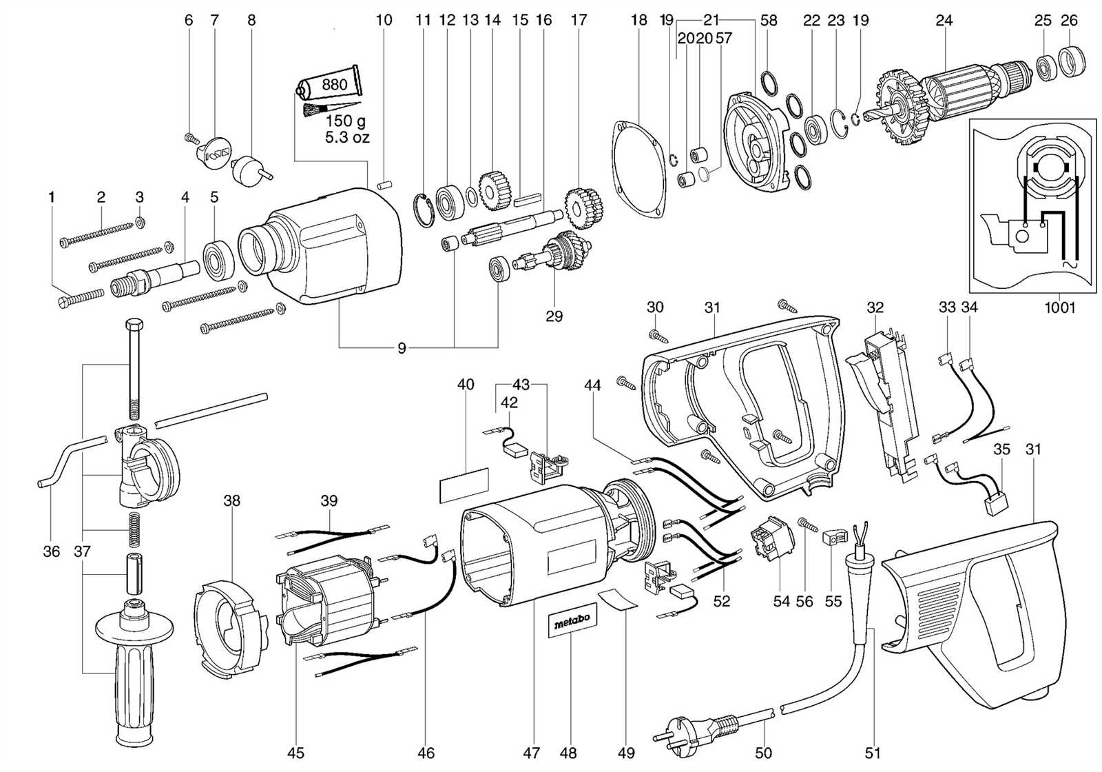
Exploded View of Drill Parts
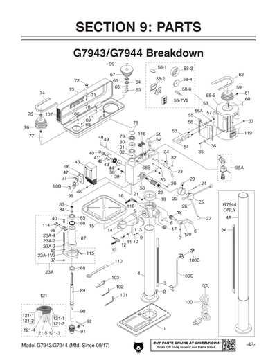
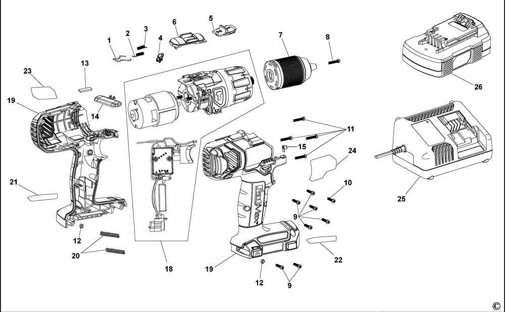
An exploded illustration provides a comprehensive look at the individual elements that make up a handheld power tool. It allows for better understanding of how each component fits and functions within the overall assembly, making it easier to identify issues, carry out repairs, or even perform regular maintenance.
By visualizing the tool in this way, users can see the placement of internal and external elements in relation to each other, aiding in tasks such as replacing worn components or understanding the construction layout.
- Motor Assembly: The core element responsible for generating motion, connected to other key mechanisms for energy transfer.
- Gear Mechanism: Facilitates the transfer of motion from the central source to the rotating output.
- Chuck System: A gripping section that secures various attachments for different tasks.
- Trigger and Handle: Provide the user interface for activating and controlling the device, with ergonomic considerations for ease of use.
- Cooling Components: Help manage heat by dissipating warmth generated during extended operation.
This type of visualization not only helps with identifying individual elements but also clarifies how they interconnect within the tool
Identifying Drill Internal Mechanisms
Understanding the inner workings of a power tool can help users maintain it effectively and troubleshoot issues with confidence. Familiarizing oneself with the various components that operate within the device allows for better insight into how it functions and contributes to the overall performance. Each element plays a role in transferring energy, adjusting speeds, and ensuring smooth operation during use.
Core Functional Components
The internal structure typically includes elements responsible for converting electrical energy into mechanical movement. For example, the motor generates rotational force, while a transmission system controls the speed and torque. Additionally, a clutch may be present, which helps in managing the applied force and prevents damage to the tool under excessive load.
Energy Transfer and Control Systems
Within the device, gear assemblies transmit rotational motion from the motor to the output shaft. These gears vary in size and shape to achieve different speed ratios and power levels. The control switch, often linked to an electronic module, regulates the flow of electricity, allowing for precise adjustments to the operating speed and overall responsiveness.
Breakdown of Drill Housing Elements
The structure of the power tool is crucial for its functionality and durability. Each component plays a significant role in ensuring efficient operation, contributing to the overall performance and user experience. Understanding the various elements that constitute the outer casing provides insights into how they work together to facilitate effective usage.
| Component | Description |
|---|---|
| Outer Shell | This is the primary covering that protects internal mechanisms and provides a grip for users. |
| Motor Housing | Encloses the motor and is designed to dissipate heat, ensuring optimal performance during operation. |
| Trigger Assembly | Controls the activation of the tool, allowing for precise operation and safety features. |
| Handle | Provides a stable and comfortable grip, allowing for better control and maneuverability. |
| Ventilation Slots | Facilitate airflow to cool the internal components, preventing overheating during extended use. |
Drill Motor Assembly Overview
This section provides a comprehensive understanding of the components that make up the power unit of a handheld tool commonly used in construction and woodworking. The assembly plays a crucial role in converting electrical energy into mechanical movement, allowing for efficient operation in various tasks. Each element within this system is designed to work in harmony, contributing to the overall functionality and performance of the equipment.
Key Components
The power unit consists of several essential elements, each serving a specific purpose. Understanding these components is vital for effective maintenance and troubleshooting. Below is a brief description of the main constituents:
| Component | Function |
|---|---|
| Motor | Converts electrical energy into rotational force. |
| Gearbox | Adjusts speed and torque for optimal performance. |
| Power Switch | Controls the on/off functionality of the device. |
| Casing | Protects internal components and provides structural support. |
Importance of Proper Assembly
Ensuring the correct assembly of these elements is crucial for the longevity and efficiency of the tool. Any misalignment or incorrect installation can lead to performance issues or mechanical failures. Regular inspections and adherence to manufacturer guidelines can help maintain the integrity of the power unit, ultimately enhancing the user experience.
Role of the Chuck in Drills
The chuck serves a crucial function in the operation of rotational tools, acting as the mechanism that securely holds the bit in place. Its ability to provide stability and grip directly influences the effectiveness and precision of the tasks being performed. Understanding the significance of this component can enhance users’ knowledge of their tools and improve their overall performance.
Functionality and Types
The primary role of the chuck is to enable the quick and easy exchange of bits, allowing users to adapt to various materials and tasks. There are different types of chucks, including keyless and keyed options, each offering unique advantages. Keyless chucks allow for fast bit changes without the need for additional tools, while keyed chucks provide a tighter grip, particularly useful for heavy-duty applications.
Impact on Performance
A well-functioning chuck ensures optimal torque transfer from the tool to the bit, which is vital for efficient drilling. When the chuck is worn or damaged, it can lead to slippage and decreased accuracy. Regular maintenance and timely replacement of this component are essential to maintain high performance and prolong the lifespan of the tool.
Trigger Mechanism and Its Function

The trigger mechanism serves as a critical component in the operation of power tools, playing a vital role in controlling their activation. This system is designed to provide a user-friendly interface, allowing for precise handling and enhanced safety during usage. By integrating various elements, the mechanism ensures a seamless interaction between the user and the tool, enabling efficient performance and effective control over the applied force.
Components of the Trigger Mechanism
The assembly typically comprises several essential elements, including a lever, spring, and electrical contacts. The lever acts as the primary interface, allowing users to initiate or cease operation with minimal effort. The spring provides necessary resistance, ensuring that the lever returns to its default position when released. Additionally, the electrical contacts facilitate the flow of power to the tool, activating the motor upon engagement of the lever.
Importance of Proper Functioning
A well-functioning trigger mechanism is crucial for safety and efficiency. Malfunctions can lead to unintended activation or inoperability, posing risks to users. Regular maintenance and checks are essential to ensure that all components are in optimal condition, thereby extending the lifespan of the tool and enhancing user experience. Understanding this mechanism empowers users to utilize their tools more effectively and safely.
Drill Gearing System Details
The gearing mechanism plays a crucial role in the operation of power tools, enabling efficient transfer of energy from the motor to the cutting mechanism. This system comprises various components that work together to regulate speed and torque, ensuring optimal performance during use.
At the heart of this mechanism lies the gear set, which typically includes pinions and cogwheels. These elements are meticulously designed to mesh seamlessly, providing the necessary mechanical advantage. The arrangement of these gears affects the rotational speed and force transmitted, which can be tailored to suit different applications.
Furthermore, gear ratios are essential in determining the relationship between input and output speeds. By adjusting these ratios, operators can achieve varying levels of power and precision. High gear ratios favor speed, making them ideal for tasks requiring rapid movement, while lower ratios enhance torque, suitable for heavy-duty applications.
In addition to the gear arrangement, the selection of materials significantly influences the durability and efficiency of the system. High-quality metals and composites are often utilized to withstand wear and tear, ensuring a longer lifespan and consistent performance under demanding conditions.
Power Source Connection Points
Understanding the various connection points for the energy supply is essential for ensuring optimal functionality. These locations play a critical role in facilitating a stable and efficient transfer of power, allowing the equipment to perform effectively during operation. Properly managing these connection points contributes significantly to the overall performance and safety of the device.
Identifying Connection Locations
Each piece of equipment features specific areas designed for power input. Recognizing these locations helps users ensure correct and secure connections, minimizing the risk of electrical issues. Typically, these points include terminals and sockets, which are clearly marked to guide proper attachment of power sources.
Importance of Secure Connections
Maintaining secure connections at the power input locations is vital for preventing electrical faults and ensuring the longevity of the device. Loose or improperly attached connections can lead to inconsistent performance and potential hazards. Regularly inspecting these points for wear and ensuring they remain clean and tightly connected can significantly enhance operational reliability.
Drill Maintenance Parts Identification
Proper upkeep of your tool requires a thorough understanding of its components. Recognizing each element and its function is essential for effective maintenance. This knowledge helps ensure optimal performance and prolongs the lifespan of the equipment. Familiarity with the various sections allows users to identify issues quickly and take appropriate action, preventing costly repairs.
Key Components Overview
The following table summarizes the critical elements commonly found in this equipment, their functions, and maintenance tips for each:
| Component | Function | Maintenance Tips |
|---|---|---|
| Motor | Powers the mechanism | Keep clean and lubricated |
| Chuck | Holds the bit securely | Inspect for wear and debris |
| Switch | Controls the operation | Test functionality regularly |
| Housing | Encases internal components | Check for cracks or damage |
| Power Cord | Supplies electrical current | Look for fraying or cuts |
Importance of Regular Checks
Conducting routine inspections of each element is vital for maintaining the tool’s efficiency. Identifying worn or damaged components early can prevent unexpected breakdowns. By establishing a maintenance schedule, users can ensure that each part functions correctly, contributing to the overall reliability of the equipment.