When maintaining or repairing specialized equipment, understanding the structure and arrangement of its elements is crucial. This allows for efficient troubleshooting and enhances the ability to perform precise replacements. A visual breakdown of the equipment’s internal configuration provides users with a clear perspective on how each element fits within the larger system.
Knowing the individual components and their roles helps operators keep their tools in optimal working condition. By familiarizing yourself with the layout, it becomes easier to identify issues and select the right solutions, ensuring longevity and peak performance. Whether you’re a seasoned professional or someone new to tool maintenance, this guide will clarify the inner workings of your equipment.
With a closer look at the internal setup, users can confidently approach repairs and replacements. This guide serves as a valuable resource for anyone looking to enhance their understanding of tool mechanics, making complex repairs manageable and efficient.
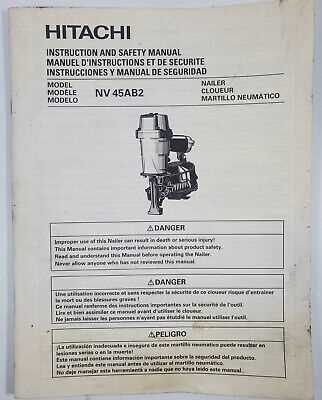
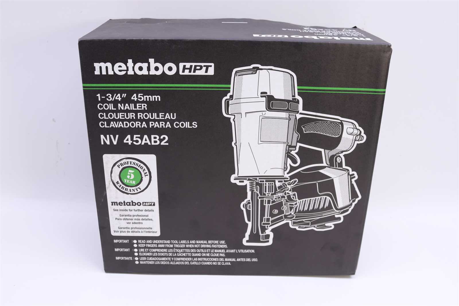
Overview of Hitachi NV45AB2 Nail Gun Components
This model of pneumatic nailer is known for its precision and efficiency, making it a popular choice for both professionals and DIY enthusiasts. The design incorporates several crucial elements, each playing a key role in ensuring smooth operation and reliability. Understanding the various components is essential for maintaining and troubleshooting the tool effectively. Below is an outline of its main features and how they interact to deliver top performance.
Main Body and Firing Mechanism
The core structure includes a robust housing that holds the firing system, which is responsible for driving the fasteners. This section also houses the trigger assembly, which initiates the nailing process. A built-in exhaust port ensures proper air release, while the magazine feeds the nails efficiently.
Handle and Control Systems
The ergonomic handle provides comfort during extended use, while the depth adjustment control allows for precision when driving nails into various materials. A safety lock mechanism prevents accidental firing, enhancing user security.
| Component | Description | |||||||||||||||||||
|---|---|---|---|---|---|---|---|---|---|---|---|---|---|---|---|---|---|---|---|---|
| Main Housing | Encloses the firing system and provides structural integrity. | |||||||||||||||||||
| Trigger Assembly | Activates the firing mechanism when pressed. | |||||||||||||||||||
| Magazine | Holds and feeds nails into the firing chamber. | |||||||||||||||||||
| Depth Adjustment | Allows control over nail depth for different surfaces. | |||||||||||||||||||
Exhaust Port
Main Body and Frame StructureThe central unit and overall framework are designed with a robust and durable construction to ensure long-lasting performance. Every component is intricately aligned to provide balance and stability during operation. This section focuses on the foundation that supports the entire mechanism, making it essential for smooth and efficient functionality. Core FrameworkThe primary structure is engineered to withstand significant pressure, maintaining its integrity even under challenging conditions. The materials used in the frame are carefully selected to combine lightweight design with exceptional strength, ensuring both mobility and resilience. Precision in assembly guarantees minimal vibrations, enhancing the overall user experience. Protective CasingThe exterior casing acts as a shield, safeguarding the internal mechanisms from external impacts and wear. It not only protects but also facilitates easier handling through its ergonomic design. With a focus on user comfort, the frame incorporates key features that reduce strain during prolonged use, ensuring reliable performance. Air Inlet and Pressure MechanismThe airflow system is a key component responsible for ensuring proper functioning by directing air through the tool. This controlled air movement drives various internal processes that ultimately result in the efficient performance of the device. The air supply must be consistent and properly managed to avoid interruptions during operation. Air Inlet Valve FunctionalityThe air inlet valve plays a crucial role in controlling the amount of air entering the system. When activated, it allows a steady flow of air into the device, ensuring that all internal components receive the necessary pressure to function correctly. Any inconsistency or blockage in the valve can lead to reduced performance or a complete stoppage of the tool’s operations. Pressure Regulation and MaintenanceMaintaining optimal pressure levels within the system is essential for consistent output. The pressure mechanism ensures that air pressure remains within the required range, preventing malfunctions. Regular checks on the pressure regulator and its components can help identify issues before they impact performance. Proper maintenance of these elements ensures the system operates smoothly and efficiently. Trigger Assembly and Safety FeaturesThe mechanism responsible for initiating the tool’s operation is designed with precision, ensuring smooth control during use. Understanding how this part works allows users to maintain optimal performance, ensuring each task is completed efficiently and safely. The trigger system plays a vital role in controlling the power and speed, while integrated safety measures prevent accidental activation. Core Elements of the Trigger SystemThe trigger system consists of several key components that work together seamlessly. These include a responsive trigger mechanism, connected to internal parts that manage power flow. This design ensures that, with minimal effort, the tool responds immediately to the user’s input. Additionally, the system is designed to provide feedback, allowing for precise control over the operation. Key Safety MechanismsBuilt-in safety features are essential to prevent unintentional activation and ensure user protection. These include a locking mechanism that prevents the tool from being engaged accidentally when not in use. Moreover, the safety lock ensures that even during transportation or handling, the risk of accidental discharge is minimized. Each of these features works together to ensure both user safety and reliable operation in various conditions. Understanding the Magazine and Nail Feeding SystemThe magazine and nail feeding system is a critical component in ensuring smooth operation, allowing nails to be efficiently stored, aligned, and delivered for quick and continuous use. This system functions to maintain consistent nail positioning while enabling easy loading and minimal interruptions during work. Its design promotes seamless nail advancement and prevents jamming, ensuring a steady workflow without unnecessary pauses. The table below provides an overview of the key elements that enable the nail feeding system to function properly:
Piston and Driver Blade Functionality
The efficiency of fastening tools greatly relies on the interaction between the piston and the driver blade. These components play a crucial role in the operation of tools designed for driving fasteners into various materials. Understanding their functionality helps in appreciating how they contribute to the overall performance of the device. The piston acts as a driving force, transferring energy from the power source to the driver blade. This energy transfer is essential for achieving the necessary force to drive fasteners effectively. The driver blade, in turn, engages with the fastener, guiding it into the material while ensuring precision and stability during the process.
Overall, the harmonious functioning of the piston and driver blade is vital for achieving optimal results in fastening applications. Regular maintenance and proper adjustments ensure that these components perform effectively, contributing to the longevity and reliability of the tool. Exhaust and Ventilation SystemThe effective management of air flow and waste gases is crucial in any machinery that relies on combustion processes. This section delves into the essential components and functionalities of the systems designed to maintain optimal air circulation and eliminate harmful emissions. A well-designed exhaust and ventilation setup not only enhances performance but also safeguards the integrity of the equipment. Key Components
Benefits of Proper Ventilation
Handle Grip and User Comfort EnhancementsEnsuring user comfort and ease of use is essential in the design of handheld tools. A well-designed handle grip can significantly enhance the overall experience, allowing for extended usage without fatigue. Various ergonomic improvements can be incorporated to provide optimal comfort and control during operation.
Implementing these enhancements not only increases user satisfaction but also contributes to improved efficiency and productivity. Prioritizing comfort leads to better tool handling and reduced risk of injuries, ultimately creating a more enjoyable user experience. Bumper and Impact Absorption PartsThe components responsible for cushioning and protecting machinery during collisions play a crucial role in ensuring safety and longevity. These elements are designed to absorb shock and minimize damage, providing essential support to the overall structure. Understanding their functionality is key to maintaining equipment efficiency and performance. Functionality of Protective ElementsProtective elements are engineered to reduce the impact force exerted during an incident, thereby safeguarding internal mechanisms from harm. The use of high-quality materials enhances their ability to absorb shocks, ensuring that the equipment can withstand various operational challenges. The durability of these components significantly contributes to the reliability and operational lifespan of the machinery. Maintenance and CareRegular inspection and maintenance of cushioning components are vital for optimal performance. Signs of wear or damage should be addressed promptly to prevent further issues. By ensuring these elements remain in good condition, operators can avoid costly repairs and extend the functional life of the equipment. Exploring the Contact Arm MechanismThe contact arm mechanism plays a crucial role in various devices, serving as a pivotal component that facilitates interaction between different elements. Understanding its design and function is essential for appreciating how these systems operate effectively. This section delves into the intricacies of this mechanism, highlighting its significance and operational dynamics. Functionality and ImportanceThis mechanism is designed to ensure reliable performance through a series of interconnected parts that work harmoniously. Here are some key functions:
Components of the Mechanism
Several essential elements comprise the contact arm assembly, each contributing to its overall functionality:
Each of these components is designed to work in unison, ensuring the mechanism performs optimally and meets the demands of its intended application. Depth Adjustment Mechanism for NailsThe ability to precisely modify the depth at which fasteners are driven into various materials is crucial for achieving optimal results in construction and repair tasks. This mechanism allows users to adapt the tool’s performance according to the specific requirements of the project, ensuring that nails are securely embedded without damaging the surrounding surfaces. Functionality and ImportanceUnderstanding the functionality of the depth adjustment feature can greatly enhance efficiency and accuracy. Key aspects include:
Adjustment MechanismThe mechanism typically involves the following components:
By effectively utilizing the depth adjustment mechanism, users can ensure optimal performance, tailored to specific project demands. Maintenance of O-Rings and SealsProper upkeep of flexible rings and sealing elements is crucial for ensuring the longevity and efficiency of various mechanical systems. These components play a vital role in preventing leaks and maintaining pressure within assemblies. Regular inspection and maintenance can significantly extend their lifespan, reducing the likelihood of costly repairs or replacements. Regular Inspection: Frequent checks for wear, damage, or deformation are essential. Signs of deterioration, such as cracks or discoloration, indicate that these components may need to be replaced. It’s important to monitor for any unusual wear patterns, as these can signal issues within the overall system. Cleaning: Keeping seals and rings clean is vital for their optimal performance. Dirt, debris, and foreign substances can compromise their effectiveness. Use appropriate cleaning solutions that do not damage the materials. A soft cloth or brush can effectively remove contaminants without scratching surfaces. Replacement: When deterioration is detected, timely replacement is critical. Ensure that new components are of high quality and compatible with the specific application. Installing seals and rings correctly is crucial to avoid future leaks or failures. Lubrication: Applying the right lubricant can enhance the performance of flexible rings and seals, reducing friction and wear. Use lubricants recommended by the manufacturer to ensure compatibility and effectiveness. Avoid using petroleum-based products unless specifically advised, as they can degrade certain materials. Repair and Replacement of Worn ComponentsMaintaining the functionality of machinery often involves addressing the wear and tear of its various elements. Over time, components may degrade, affecting overall performance. This section focuses on the essential steps for identifying and replacing these aged parts to ensure the equipment operates smoothly. To effectively manage the replacement process, consider the following steps:
By adhering to these steps, users can prolong the life of their equipment and maintain optimal performance. Regular maintenance not only enhances reliability but also reduces the likelihood of unexpected breakdowns. |

