Understanding the structure and functionality of essential machinery is crucial for ensuring efficient maintenance and operation. This guide aims to provide a detailed look into the assembly and internal configuration of widely used construction machines. A clear overview of the mechanical elements will empower technicians and operators alike to streamline repairs and keep equipment running smoothly.
Whether dealing with hydraulic systems, powertrain assemblies, or other vital sections, having a clear map of the interconnected components is invaluable. The following sections will break down the key elements, their relationships, and how to identify common wear points. Armed with this knowledge, you will be better equipped to manage technical challenges and prolong the lifespan of the equipment.
Additionally, we’ll dive into maintenance strategies and troubleshooting techniques, focusing on the most common breakdowns and repair tactics. Each component’s role will be analyzed to ensure you have a well-rounded understanding of how these machines operate in real-world scenarios.
Understanding the JCB 1400B Backhoe Structure
The structure of heavy-duty construction machinery is crucial for its efficient operation. Every component is designed to work together seamlessly, creating a balance between power, precision, and durability. Understanding how these elements fit together helps operators maximize performance while ensuring the longevity of the machine. This section focuses on the main structural components, detailing their functions and interactions.
Main Frame and Chassis
The core of the machine’s body is the main frame, providing the foundation for all other components. It supports the hydraulic systems, engine, and operator’s cabin, ensuring stability during demanding tasks. The chassis, built from reinforced materials, absorbs the stresses encountered during excavation or lifting, distributing the force evenly across the entire structure.
Hydraulic Arm and Loader
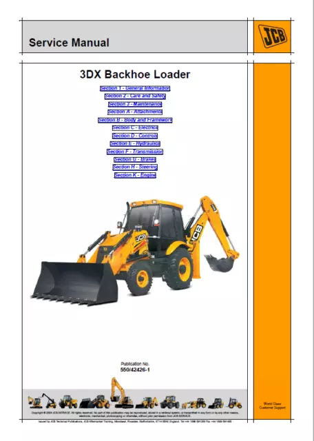
The hydraulic arm is essential for the machine’s versatility. It allows for digging, lifting, and moving materials with great precision. The loader, mounted at the front, assists in scooping and transporting heavy loads. These systems rely on robust hydraulics to provide fluid and controlled movements, ensuring that even the heaviest tasks can be handled with ease.
Key Components of the Hydraulic System
The hydraulic mechanism plays a crucial role in the functionality of heavy-duty machinery, enabling smooth and precise operations. It utilizes pressurized fluid to generate the force required for lifting, digging, and moving materials. Understanding the main elements of this system is essential for maintaining performance and ensuring efficiency.
Pump: This component generates the necessary flow of hydraulic fluid throughout the system. The pump’s efficiency directly impacts the overall power and responsiveness of the machine.
Cylinders: Hydraulic cylinders convert fluid pressure into linear force, driving the extension and retraction needed for various tasks. Their durability and condition are vital for seamless motion and load handling.
Valves: Control valves regulate the direction, pressure, and flow of the fluid. These elements are essential for the precise management of different machine functions, ensuring that the correct
JCB 1400B Engine and Transmission Layout
The power and drive systems are the core elements ensuring efficient operation. Understanding the placement and interaction of these components is crucial for maintaining smooth functionality and optimizing performance. The layout of the motor and transmission plays a pivotal role in balancing power distribution, enhancing mobility, and ensuring reliable operations in various working conditions.
Engine Configuration
The motor system is designed to provide high torque and steady performance. Key elements of the layout include:
- Cylinder arrangement to maximize combustion efficiency.
- Fuel injection system for precise fuel management.
- Cooling mechanisms ensuring the engine operates within safe temperature ranges.
Transmission System
The transmission transfers power from the engine to the wheels, making mobility and versatility possible. The following are the main components:
- Gearbox, allowing seamless shifting between gears.
- Drive shaft, responsible for transmitting rotational power.
- Final drive units that further adjust power distribution to the wheels.
Together, the powertrain and the gear mechanisms form an integrated system that maximizes mechanical efficiency and operational stability in diverse conditions.
Backhoe Arm and Bucket Mechanism Overview
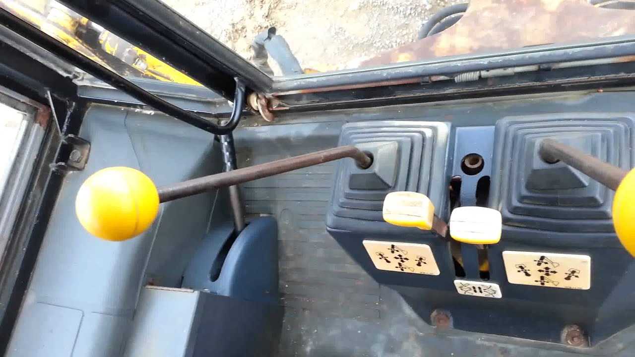
The excavator’s lifting system consists of several interconnected components designed to work in harmony. These elements ensure the controlled movement of the arm, allowing it to dig, lift, and maneuver materials efficiently. Understanding the primary elements and their functions can help operators achieve optimal performance.
Main Structural Components
- Arm (Dipper Stick): The middle section, connecting the boom to the digging tool, primarily responsible for extending and retracting during operation.
- Boom: The uppermost segment, which serves as the main lifting arm, providing vertical reach and stability when moving heavy loads.
- Bucket: The digging or loading tool at the end of the arm, specifically designed to handle various materials such as soil, gravel, or debris
Identifying Electrical Wiring in the JCB 1400B

Understanding the electrical system is essential for the maintenance and repair of construction equipment. The wiring network connects various electrical components, ensuring the proper operation of essential functions such as lighting, engine ignition, and control systems. Proper identification of these wires is crucial for troubleshooting and preventing future issues.
Key Wiring Connections and Components
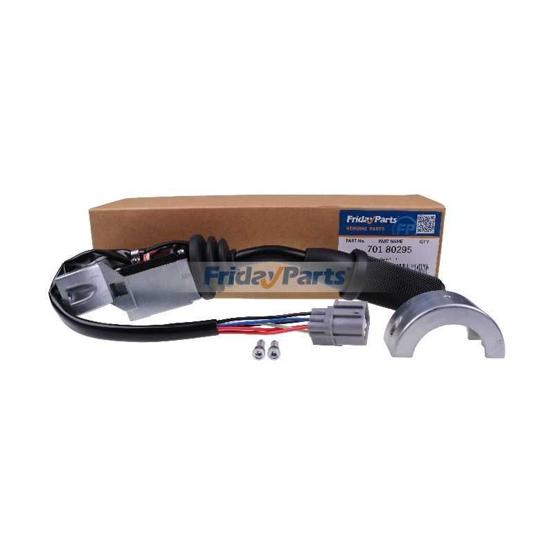
The electrical layout includes several critical wires and connections that need careful attention. These wires run through various circuits, such as lighting, ignition, and control modules. Each section of the wiring harness has specific color codes and labeling, making it easier to identify which component it connects to. Key areas to focus on include the dashboard, the engine bay, and external lights.
Wiring Color Codes and Functions
Each wire in the system is color-coded for easy identification. This color coding ensures that the wires are connected to the correct components during repairs. Below is a basic guide to common wire colors and their functions:
Wire Color Function Steering and Control System Breakdown 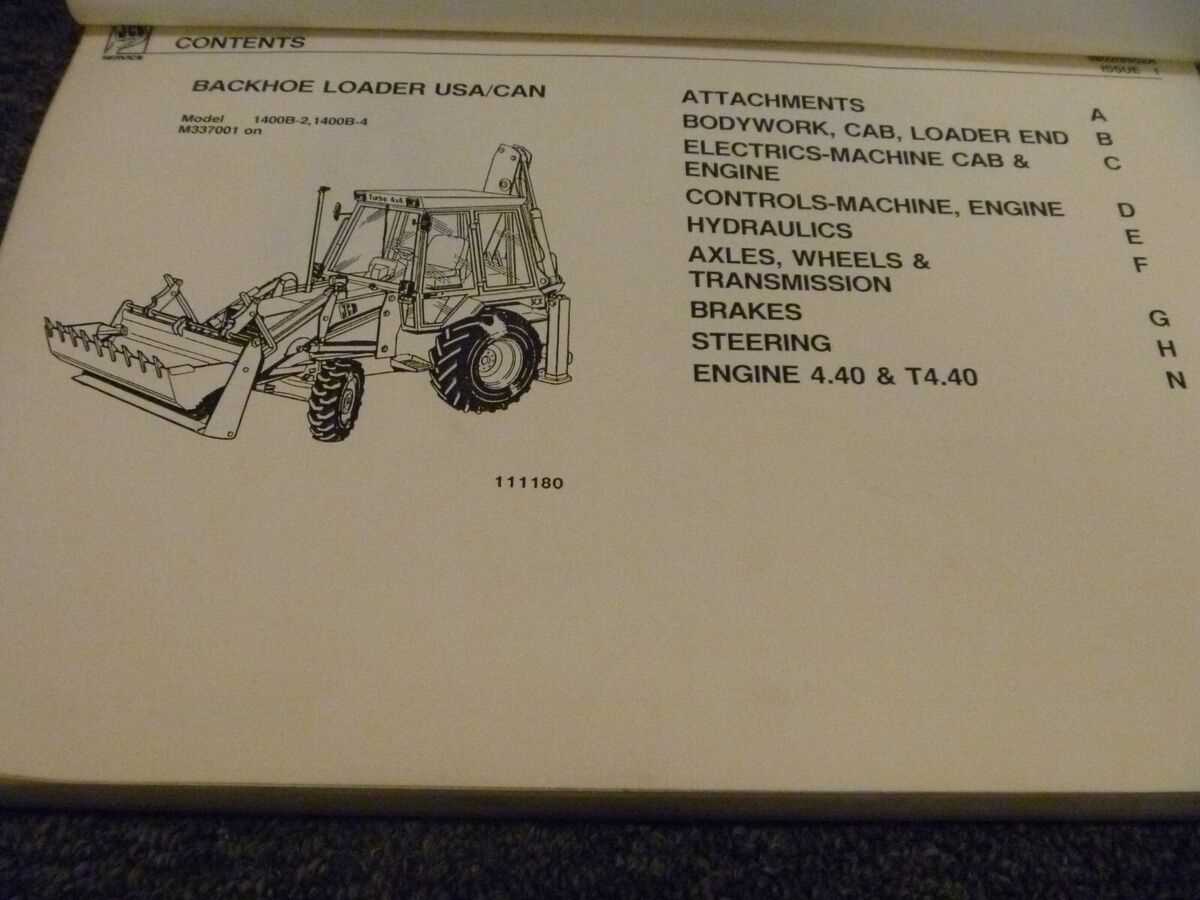
The steering and control mechanism of heavy machinery plays a crucial role in ensuring precise maneuverability and operational efficiency. Understanding the components that make up this system is essential for effective maintenance and troubleshooting. This section delves into the intricate elements involved, outlining their functions and interrelationships.
Key Components
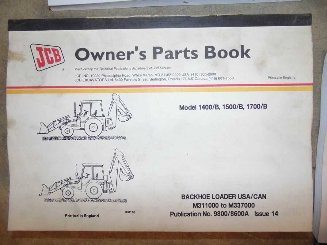
- Steering Wheel: The primary interface for the operator, allowing for direction control.
- Hydraulic Cylinders: Responsible for converting hydraulic pressure into linear movement for steering.
- Control Valves: Manage the flow of hydraulic fluid, enabling smooth operation of steering functions.
- Linkage System: Connects the steering wheel to the hydraulic components, facilitating motion transfer.
- Pivot Points: Allow for rotation and flexibility in the steering mechanism.
Functionality Overview
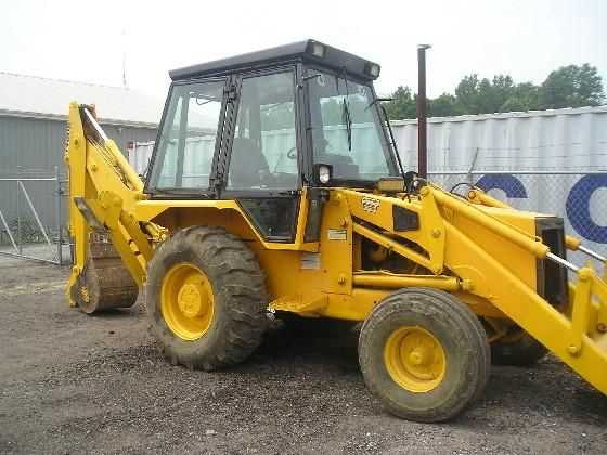
Each component in the steering assembly works in harmony to provide responsive handling. The operator turns the steering wheel, which activates the hydraulic cylinders through the control valves. This action generates the necessary force to adjust the angle of the machine, allowing it to navigate various terrains. Regular inspection and maintenance of these elements are vital to prevent operational failures and ensure safety.
Understanding this system not only enhances operational effectiveness but also contributes to the longevity of the machinery. By familiarizing oneself with these components, operators can identify potential issues early and take corrective actions promptly.
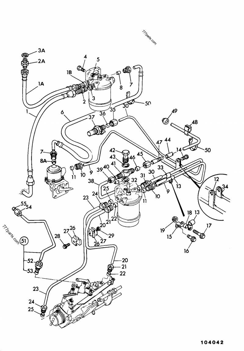
How to Locate JCB 1400B Fuel System Parts
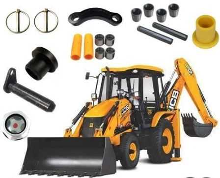
Finding the essential components of the fuel delivery system for your machine is crucial for its efficient operation. This process involves identifying specific elements and understanding their layout within the system. By familiarizing yourself with the components and their functions, you can ensure proper maintenance and timely replacements.
Step 1: Consult the Manual
The first step in locating these components is to refer to the operator’s manual. This document typically contains valuable information about the assembly, including diagrams and detailed descriptions of each element, making it easier to pinpoint locations and understand their interconnections.
Step 2: Use Online Resources
Numerous online platforms offer resources such as schematics and troubleshooting guides. Searching for your machine’s model along with terms related to the fuel system can yield useful diagrams and videos that illustrate the layout and placement of crucial elements.
Step 3: Join Forums and Communities
Engaging with online communities dedicated to machinery can provide insights from other users. Members often share their experiences, including where to find specific components and tips for replacement or repair. This collective knowledge can be invaluable for troubleshooting and maintenance.
Step 4: Visit Authorized Dealers
Authorized dealerships often have detailed knowledge of the machinery and can assist you in locating parts. They may also provide access to official resources that are not readily available online, ensuring you have the most accurate information.
Step 5: Physical Inspection
If you have access to the machine, conducting a physical inspection is vital. Look for labels or markings on the components, as these often indicate the specific part numbers or functions. This direct approach can help you confirm what you need before making any purchases.
By following these steps, you can effectively locate the elements of the fuel delivery system, ensuring your equipment operates smoothly and efficiently.
Brake and Axle Parts of the JCB 1400B
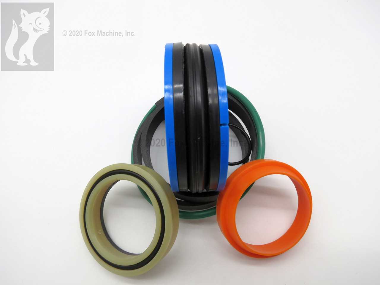
The braking and axle system of heavy machinery plays a crucial role in ensuring operational efficiency and safety. This section provides an overview of the essential components involved in these systems, which contribute to the overall performance of the equipment. Understanding the configuration and function of these elements is vital for maintenance and troubleshooting tasks.
Brake Components
Effective stopping power is achieved through a well-designed braking mechanism. The key components include hydraulic cylinders, pads, and rotors, each serving a specific function in the braking process. Regular inspection and timely replacement of worn elements can prevent potential failures.
Axle Assembly
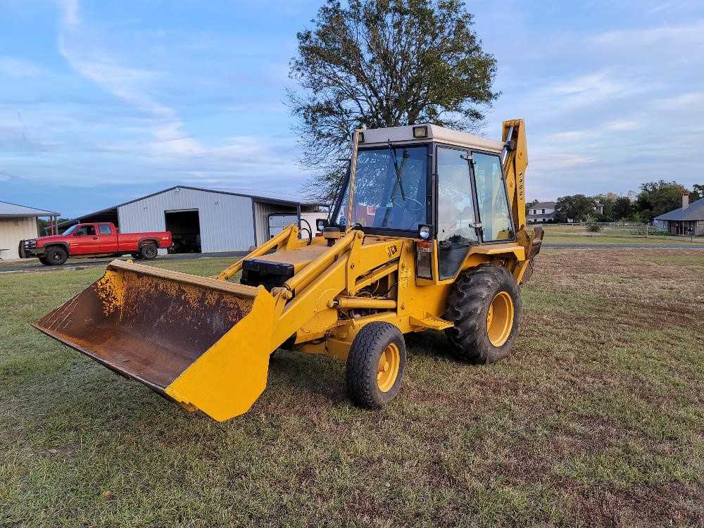
The axle assembly is integral to the mobility and stability of the machine. It comprises shafts, bearings, and differentials, all working together to support weight and facilitate movement. Proper lubrication and alignment are essential to maintain the longevity of these parts.
Component Description Brake Cylinder Activates the braking mechanism when hydraulic pressure is applied. Brake Pad Friction material that contacts the rotor to slow down the wheels. Rotor Disc that the brake pads clamp onto to create stopping force. Axle Shaft Transfers power from the engine to the wheels, enabling movement. Bearings Support the axle shaft and reduce friction during operation. Differential Allows for differences in wheel speed during turns, improving traction. Cooling System Components and Diagram
The cooling system plays a vital role in maintaining optimal operating temperatures for heavy machinery, ensuring efficiency and longevity. Understanding its components and how they function together is essential for effective maintenance and troubleshooting.
The primary elements of a cooling system include:
- Radiator: The component responsible for dissipating heat from the coolant to the air.
- Water Pump: Circulates the coolant throughout the engine and radiator.
- Thermostat: Regulates the flow of coolant based on temperature, maintaining a consistent engine temperature.
- Coolant Reservoir: Holds excess coolant and allows for expansion and contraction during heating and cooling cycles.
- Cooling Hoses: Transport coolant between the engine, radiator, and other components.
Each of these elements works in concert to effectively manage engine temperatures. The following list outlines their interconnections:
- The water pump draws coolant from the reservoir and pushes it into the engine.
- The thermostat monitors engine temperature and opens or closes to control coolant flow.
- As the engine heats up, the coolant absorbs the heat and flows to the radiator.
- The radiator cools the hot coolant using airflow, facilitated by the vehicle’s movement or a fan.
- Cooled coolant returns to the engine, completing the cycle.
Understanding the layout and functioning of these components aids in diagnosing potential issues and ensures that the machinery operates smoothly, reducing the risk of overheating and subsequent damage.
Guide to the JCB 1400B Suspension Setup
The setup of a construction vehicle’s suspension system is crucial for optimal performance and stability on various terrains. Understanding how to properly configure this system can enhance maneuverability, improve operator comfort, and extend the lifespan of the machinery. This guide focuses on the essential components and adjustments necessary for a robust suspension system.
Understanding Suspension Components
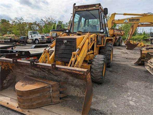
A well-functioning suspension comprises several key elements, including springs, shock absorbers, and control arms. Each component plays a vital role in absorbing shocks and maintaining contact with the ground. Springs provide resilience and support, while shock absorbers dampen the impact of uneven surfaces. Regular inspection and maintenance of these parts ensure they operate efficiently.
Adjustments for Optimal Performance
To achieve the best results, it is important to adjust the suspension settings according to the specific application and load requirements. Fine-tuning the spring tension and damping settings can significantly affect the vehicle’s handling characteristics. Operators should also consider the weight distribution when configuring the system, as improper alignment can lead to premature wear and reduced stability.
Understanding Loader Assembly in the JCB 1400B
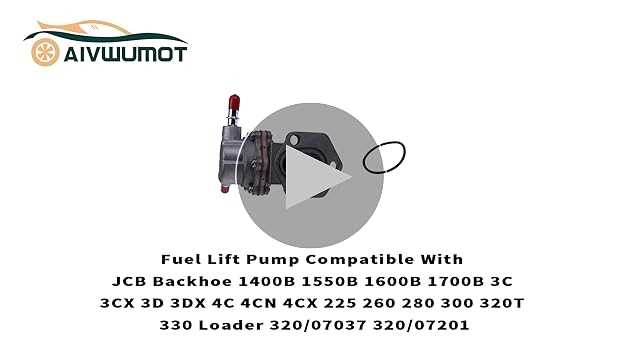
The loader assembly plays a crucial role in the functionality of heavy machinery, contributing to its efficiency and effectiveness in various tasks. This section delves into the intricate components that comprise this essential system, exploring how each part works in harmony to achieve optimal performance. A comprehensive grasp of this assembly is vital for operators and technicians alike, as it enhances operational capabilities and ensures maintenance needs are effectively addressed.
At the heart of the loader assembly is the bucket, designed for optimal material handling, whether it’s lifting, digging, or transporting. The mechanism connecting the bucket to the arm allows for precise control, enabling operators to maneuver loads with accuracy. The hydraulic system is another pivotal element, providing the necessary force to operate the bucket and other components smoothly. Understanding the interplay between these parts is essential for maximizing productivity and minimizing downtime.
Additionally, the structural integrity of the loader assembly is supported by a series of linkages and joints, which must be regularly inspected for wear and tear. Proper maintenance of these components not only extends the lifespan of the machinery but also enhances safety during operation. Familiarity with the loader assembly’s layout can significantly improve troubleshooting efficiency, helping to identify issues before they escalate into more significant problems.
In summary, comprehending the loader assembly’s design and function is vital for anyone involved with this type of equipment. By knowing how each element interacts and contributes to overall performance, operators can ensure their machines operate at peak efficiency, leading to improved project outcomes.
Maintenance Tips for JCB 1400B Hydraulic Parts
Regular upkeep of hydraulic components is essential for optimal performance and longevity. Understanding how to properly maintain these systems ensures that machinery operates smoothly and efficiently, reducing the risk of costly repairs and downtime.
Here are some effective strategies to maintain hydraulic elements:
Maintenance Task Frequency Description Fluid Level Check Weekly Monitor the hydraulic fluid levels regularly to prevent system failures. Low fluid can lead to overheating and increased wear. Leak Inspection Monthly Examine hoses and fittings for any signs of leakage. Prompt repairs can prevent fluid loss and maintain system pressure. Filter Replacement Every 200 hours Replace filters as per the recommended schedule to ensure contaminants are kept out of the hydraulic fluid, promoting system health. System Flush Annually Perform a complete system flush to remove debris and old fluid, allowing fresh fluid to circulate and improve performance. Seal Inspection Every 500 hours Check seals for wear and tear. Replace any damaged seals to maintain pressure and prevent fluid loss. By adhering to these maintenance guidelines, operators can enhance the reliability of hydraulic machinery, ensuring it remains in peak condition for years to come.