kipor ig2000 parts diagram

Understanding the various elements that come together in modern equipment can be key to ensuring smooth operation and longevity. This section will guide you through the core components, explaining their functions and how they interact within the overall system. By familiarizing yourself with these elements, you can gain deeper insights into the inner workings of the device.

In addition to basic explanations, we’ll explore how these individual elements are interconnected, helping you grasp the full picture of the machine’s structure. Each element plays a vital role, and having a clear understanding of them will make it easier to address potential issues and ensure optimal performance.

Finally, we’ll discuss how recognizing the structure of these elements can assist with maintenance, repair, and upgrading tasks, allowing for better decision-making when it comes to the upkeep of your equipment. Mastering this knowledge will lead to more efficient troubleshooting and improved overall usage.

Overview of the Kipor IG2000 Components

The design of this portable power solution is based on a well-structured system of interconnected elements, each contributing to its efficient and smooth operation. The components are strategically arranged to maximize performance, ensure reliability, and support long-term functionality. By understanding how these parts work together, users can better appreciate the device’s capabilities and address potential maintenance or replacement needs effectively.

Key Functional Areas

The machine’s architecture is divided into several functional areas, each responsible for specific tasks. These include the energy generation unit, control mechanisms, and safety systems. Each area is meticulously designed to handle its role, ensuring the overall system works seamlessly. Proper maintenance and awareness of these components will lead to optimal performance.

Detailed Component List

Below is a breakdown of some of the essential elements and their functions within the system:

Key Engine Parts in the Kipor IG2000

The essential components of this compact power source work in unison to ensure reliable performance and smooth operation. These core elements are crucial for maintaining efficiency, delivering consistent energy output, and ensuring long-term durability.

Fuel System: The mechanism responsible for providing the necessary fuel for combustion. It ensures a steady flow, contributing to the overall effectiveness and responsiveness of the motor.

Ignition System: A critical feature that initiates the combustion process, converting fuel into the necessary energy to power the unit. This ensures smooth starts and efficient operation.

Cooling Mechanism: Vital for regulating temperature, this feature helps prevent overheating during extended use, contributing to the device’s longevity.

Exhaust System: Responsible for removing byproducts of combustion, this system

Electrical System Elements in the Generator

The electrical components within the generator form a vital network, responsible for converting mechanical energy into usable electrical power. Each part plays a specific role in ensuring the efficient functioning of the system, providing stability and consistency during operation. By understanding the individual elements, users can gain a clearer perspective on how energy flows through the device and how potential issues can be identified and resolved.

Core Components and Their Functions

Among the key elements, the alternator stands out, transforming the mechanical input into electrical output. This process is made possible by a rotor and stator working in harmony, generating the required power. Additionally, voltage regulation is essential, ensuring that the output remains stable and within safe levels. This system is further supported by wiring, switches, and connectors, which all contribute to the seamless transmission of energy.

Power Regulation and Safety Features

kipor ig2000 parts diagram

Beyond generation, power control is another critical function, handled by various regulators and protective mechanisms. These ensure that fluctuations in output do not lead to damage

Fuel System Breakdown for Kipor IG2000

The fuel delivery mechanism is a crucial component of any portable generator, ensuring the smooth and efficient supply of energy. By understanding the arrangement of its elements, users can maintain optimal performance and diagnose issues with ease. In this section, we’ll explore the core functions and structure of the power supply mechanism, focusing on its operational sequence and key elements.

Main Fuel Components

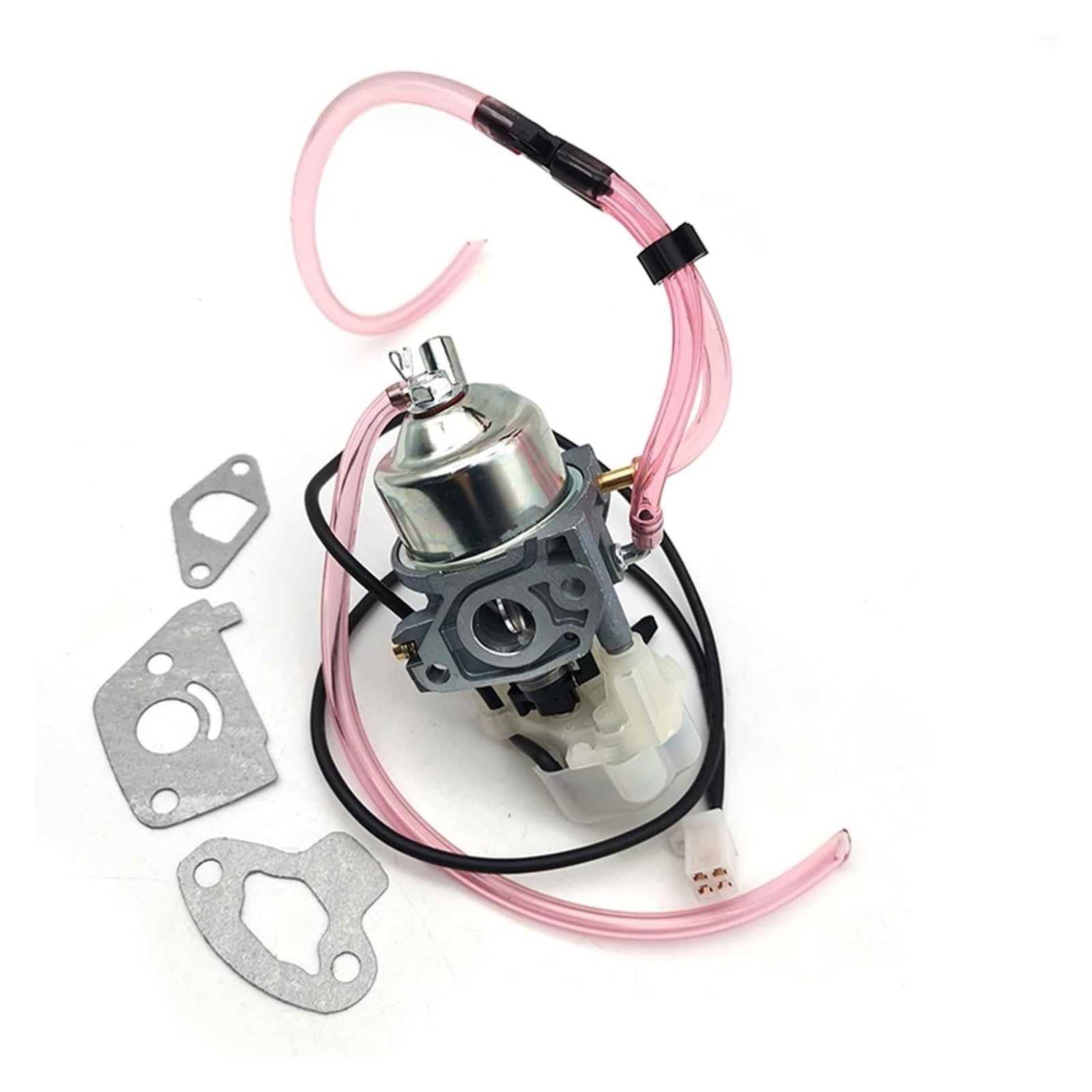
The system includes several vital components responsible for regulating and delivering fuel to the engine. Key elements such as the tank, filter, and carburetor work together to ensure the proper flow of fuel. The filter prevents debris from entering, while the carburetor manages the mixture of air and fuel for combustion.

Flow and Filtration

The liquid moves through a series of passages from the storage unit to the engine, with each section designed to perform a specific task. Proper

Cooling Mechanism and Airflow Path

The cooling system plays a crucial role in maintaining optimal performance and preventing overheating. Proper airflow management ensures that the internal components remain at a stable temperature, enhancing overall efficiency and extending the lifespan of the device. Understanding how air circulates within the unit is key to achieving effective temperature regulation.

Air Circulation Design

The design of the airflow system is carefully crafted to maximize cooling efficiency. Air enters through strategically placed vents and moves across heat-generating components. This continuous flow helps dissipate heat and maintain a balanced internal environment.

  • Air intake positioned for optimal flow.
  • Cooling fans ensuring consistent air movement.
  • Exhaust system directing warm air out efficiently

    Exhaust Components and Their Functions

    The exhaust system is a crucial aspect of any combustion engine, playing a vital role in managing emissions and ensuring optimal performance. Each component within this system serves a specific purpose, contributing to the overall efficiency and effectiveness of the engine’s operation.

    • Exhaust Manifold: This component collects exhaust gases from multiple cylinders and directs them into a single pipe. It is essential for improving engine efficiency and performance.
    • Catalytic Converter: The catalytic converter transforms harmful pollutants in the exhaust gases into less harmful substances before they exit the system. This component is key for meeting environmental regulations.
    • Muffler: The muffler reduces noise produced by the exhaust gases as they exit the engine. It ensures a quieter operation, enhancing the overall driving experience.
    • Exhaust Pipe: The exhaust pipe carries the treated gases away from the engine and out into the atmosphere. Its design influences back pressure and engine efficiency.
    • Oxygen Sensor: This sensor monitors the level of oxygen in the exhaust gases, providing critical data for the engine control unit. It helps optimize fuel mixture and improve efficiency.
    • Heat Shield: The heat shield protects surrounding components from the high temperatures generated by the exhaust system, ensuring safety and durability.

    Understanding the roles of these components is essential for effective maintenance and troubleshooting. Proper functioning of the exhaust system not only enhances performance but also contributes to environmental sustainability.

    Ignition System Parts and Layout

    The ignition system plays a crucial role in the operation of portable generators, ensuring that the engine starts efficiently and runs smoothly. This section outlines the essential components involved in the ignition mechanism and their arrangement within the assembly, providing insight into how they interact to facilitate reliable ignition.

    • Ignition Coil: This component transforms low voltage from the battery into a high voltage, which is necessary to create a spark.
    • Spark Plug: Positioned in the combustion chamber, this device ignites the fuel-air mixture, initiating the combustion process.
    • Flywheel Magnet: It is attached to the flywheel and generates a magnetic field that triggers the ignition coil when the engine turns over.
    • Ignition Switch: This switch allows the operator to turn the ignition system on or off, controlling the starting process.
    • Wiring Harness: A network of wires connects all electrical components, ensuring efficient communication and power delivery throughout the ignition system.

    Understanding the configuration of these components can aid in troubleshooting and maintenance, enhancing the longevity and reliability of the generator. Regular inspection and replacement of worn parts contribute to optimal performance.

    Control Panel Features and Buttons

    The control interface of a portable generator plays a crucial role in user interaction and functionality. This section highlights the various elements and functions that enhance usability, ensuring that the operator can easily manage power output and monitor performance.

    At the forefront of the control panel, you’ll find an on/off switch that allows for quick activation or deactivation of the unit. Adjacent to this, a series of indicator lights provide visual feedback on the operational status, including power availability and potential warnings.

    The control knobs typically allow users to adjust the output voltage and manage the power levels according to their needs. These knobs often feature clear markings for intuitive adjustments, ensuring optimal performance for various applications.

    In addition, many models incorporate circuit breakers designed to protect the generator from overloads. This safety feature is essential for maintaining the longevity of the equipment and ensuring safe operation. Furthermore, a reset button is usually included to quickly restore functionality after an interruption.

    Overall, the thoughtful design of the control panel enhances user experience by providing essential tools for efficient operation and monitoring, making it easier for individuals to manage their power requirements effectively.

    Protective Casing and Frame Details

    The protective enclosure and structural framework play a crucial role in ensuring the durability and functionality of portable generators. These components are designed to withstand various environmental factors, thereby enhancing the overall longevity of the device. Understanding their characteristics can help users appreciate the engineering behind reliable performance.

    Enclosure Features

    The casing is crafted from high-quality materials that provide robust protection against external elements. Key aspects include:

    • Weather Resistance: The outer layer is designed to repel moisture and dust, safeguarding internal components.
    • Impact Protection: Reinforced materials help absorb shocks and prevent damage from accidental falls.
    • Ventilation: Strategic openings allow for adequate airflow, ensuring optimal performance and preventing overheating.

    Frame Characteristics

    The framework offers stability and support, contributing to the overall safety of the generator. Important characteristics include:

    • Lightweight Design: The frame is engineered to be easily transportable without compromising strength.
    • Corrosion Resistance: Treated surfaces protect against rust and deterioration, extending the product’s lifespan.
    • Secure Mounting: Proper attachment points ensure that all components are held firmly in place during operation.

    Oil System Components and Locations

    The oil management system plays a crucial role in maintaining optimal performance and longevity of the equipment. This section highlights the key components involved in this system and their respective placements, ensuring efficient lubrication and functionality during operation.

    Each element of the oil management system is designed to work in harmony, providing necessary lubrication to reduce friction and wear. Understanding the configuration of these components is essential for effective maintenance and troubleshooting.

Component Function
Component Description Location
Oil Reservoir Holds the lubricating fluid required for operation. Located at the base of the unit.
Oil Pump Circulates oil to various parts of the engine. Positioned near the engine block.
Oil Filter Removes contaminants from the lubricating fluid. Mounted on the side of the engine.
Drain Plug Facilitates the removal of used oil during maintenance. Located at the bottom of the oil reservoir.
Oil Level Indicator Allows monitoring of the oil quantity. Visible from the outer casing.

Recoil Starter Assembly and Mechanism

kipor ig2000 parts diagram

The recoil starter assembly is a crucial component in various engine-driven machines, enabling easy initiation of the engine. This system employs a spring-loaded mechanism that allows users to pull a cord, which in turn activates the engine’s flywheel to commence operation.

Understanding the components of the recoil starter can enhance the maintenance and repair of the system. Below are the primary elements that constitute this assembly:

  • Starter Handle: The part grasped by the user to initiate the starting process.
  • Starter Cord: A durable line that connects the handle to the recoil mechanism, allowing the user to exert force when pulling.
  • Recoil Spring: A spring that stores energy when the cord is pulled and releases it to rewind the cord after starting.
  • Pulley: The circular component that guides the starter cord and connects to the engine’s flywheel.
  • Mounting Plate: The base that secures the recoil assembly to the engine housing, providing stability during operation.

Proper functioning of the recoil starter relies on the interaction of these parts. Regular inspections can prevent issues such as fraying cords or weakened springs, ensuring reliable performance and longevity of the mechanism.

In case of malfunction, troubleshooting should begin with examining the starter cord for any wear, followed by checking the recoil spring for proper tension. Replacing damaged components will restore functionality and enhance user experience.

Wiring and Circuitry Connections in Kipor IG2000

Understanding the electrical connections and circuit layouts in portable generators is essential for ensuring their proper functionality. This section delves into the intricacies of the wiring and circuitry, highlighting the importance of each connection for optimal performance.

Proper wiring is crucial for the safe operation of the generator. Here are some key components involved in the electrical setup:

  • Power Input Terminals: These points are where the generator receives electrical energy from the fuel source.
  • Control Panel Connections: This area houses switches and indicators that allow users to monitor and manage generator operations effectively.
  • Output Terminals: These connections deliver generated power to external devices, ensuring that electricity is available when needed.

Each of these components is interconnected through a series of wires and circuit boards, which facilitate the flow of electricity. Proper insulation and secure connections are necessary to prevent short circuits and ensure safety.

In summary, comprehending the wiring and circuitry connections in portable power units is vital for effective operation and maintenance. Familiarity with the components and their functions will aid users in troubleshooting and optimizing their equipment.

Filter Placement and Maintenance Points

Proper positioning and upkeep of filtration components are essential for optimal performance and longevity of the equipment. Ensuring that these elements are correctly installed and maintained can significantly enhance efficiency and prevent potential issues.

Filter Location

Identifying the right placement for the filter is crucial. Typically, it should be situated in a location that allows easy access for routine checks and replacements. Here are some general guidelines for filter placement:

  • Locate the filter near the air intake or exhaust area.
  • Avoid placing it in areas prone to dust accumulation.
  • Ensure it is easily accessible for maintenance without disassembling other components.

Maintenance Recommendations

Regular maintenance of the filtration system is vital for sustaining performance. Here are some key maintenance points to consider:

  1. Check the filter at regular intervals, ideally every month.
  2. Replace the filter as recommended by the manufacturer or when it appears dirty.
  3. Inspect surrounding areas for debris and clean as needed.
  4. Monitor equipment performance for any signs of reduced efficiency, which may indicate a clogged filter.