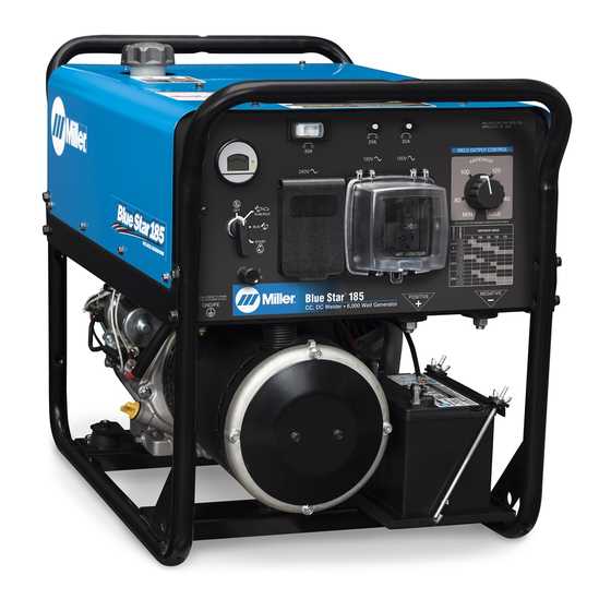
Understanding the various elements and components of technical devices is essential for ensuring smooth operation and maintenance. By familiarizing yourself with the internal structure and key mechanisms, you can quickly identify potential issues and make informed decisions regarding repairs or replacements.
In this guide, we will delve into the intricacies of equipment systems, breaking down the core units and exploring their functions. This will provide a solid foundation for those looking to gain deeper insights into how these machines work, offering a detailed examination of each crucial part.
Whether you’re an experienced technician or just starting, having a clear reference for the internal mechanisms is invaluable. Our approach focuses on clarity and precision, offering you a straightforward path to better understanding and maintaining your machinery.
Comprehensive Parts Overview
This section offers a thorough examination of the essential components and their functions within a widely recognized generator. By understanding the key elements that make up the equipment, users can enhance performance, ensure efficient maintenance, and address potential issues more effectively.
Key Components Breakdown
The generator consists of various mechanical and electrical elements that work together to deliver reliable power. Each component plays a crucial role, from the ignition system to the alternator, ensuring seamless operation under diverse conditions. Familiarity with these parts helps in diagnosing and resolving technical problems swiftly.
Maintenance and Replacement Guide
Regular upkeep of each element is critical for prolonging the device’s lifespan. Knowing when and how to replace worn-out components can prevent major malfunctions and costly repairs. The following table outlines essential elements, their functions, and rec
Essential Components of the Blue Star 185
The structure and functionality of this welding machine rely on various key elements that ensure smooth operation and efficient performance. These components work in unison to provide the necessary power and control for a range of tasks, from light to heavy-duty applications.
- Power Unit – This is the heart of the device, responsible for generating the
Understanding the Wiring Diagram for Miller Welders
Grasping the layout of electrical circuits in welding machines is essential for troubleshooting and maintenance. A clear understanding of how various components connect ensures that users can effectively manage repairs and adjustments, minimizing downtime and enhancing machine performance. This section outlines the key aspects of interpreting wiring layouts, focusing on the relationship between power sources, controls, and operational elements.
Component Function Power Supply Provides the necessary electrical input to the welding system. Control Panel Allows the operator to adjust settings and monitor performance. Welding Torch Key Engine Parts of the Miller Blue Star
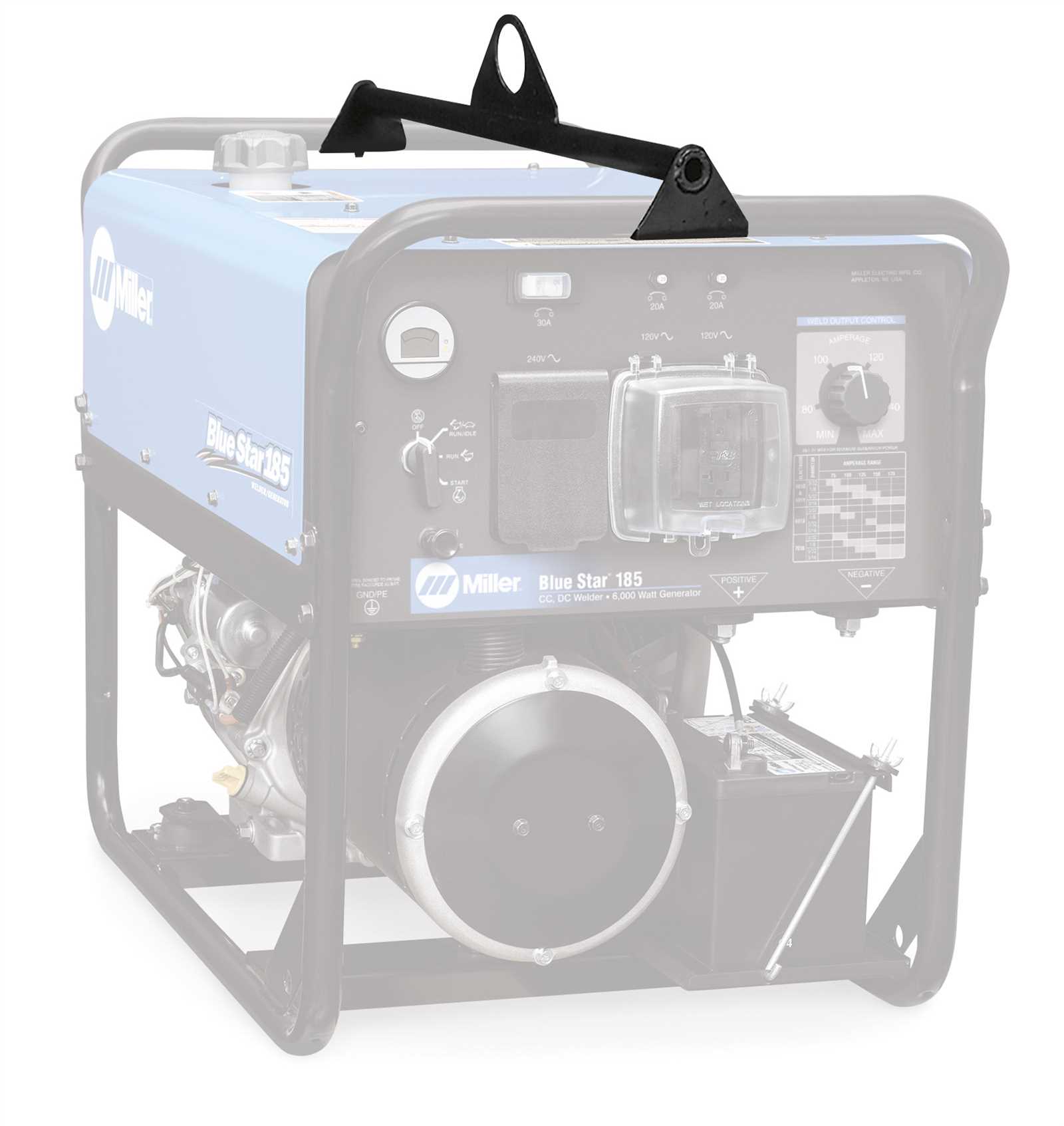
The internal components of this engine system play a crucial role in its overall performance. Understanding the essential elements that drive the machine’s functionality helps ensure smooth operation and easy maintenance. Below, we’ll explore some of the most important engine elements that contribute to its reliability and efficiency.
- Cylinder Block: The core structure of the engine, housing key moving parts and providing stability.
- Pistons: These components move within the cylinders, converting fuel into mechanical power.
- Crankshaft: Converts the linear motion of the pistons into rotational motion, driving the machine.
- Camshaft: Regulates the timing of the engine’s valves, ensuring proper intake and exhaust of gases.
- Power Generation Unit: The primary source of electricity that drives all connected equipment.
- Voltage Regulator: A component that ensures a constant output voltage, preventing surges or drops in power.
- Wiring and Connectors: These elements facilitate the flow of current between various modules, linking all parts of the system.
- Control Panel: A centralized hub that allows operators to adjust settings, monitor performance, and manage outputs.
- Cooling Mechanism: Prevents overheating by maintai
Fuel System Components in Miller Welders
The fuel system is crucial for the operation of welding machines, ensuring proper combustion and efficient power generation. It consists of several interconnected components that work together to supply, regulate, and maintain the fuel flow necessary for the welder’s engine. These parts are designed to withstand the demands of heavy-duty use and provide reliable performance over time.
Component Function Fuel Tank Stores the fuel required for the machine’s operation. Fuel Pump Delivers fuel from the tank to the engine at the correct pressure. Fuel Filter Removes impurities from the fuel to prevent clogging of the fuel system. Carburetor Mixes air and fuel in the correct ratio for combustion. Fuel Lines Transport fuel between the tank, pump, filter, and carburetor. Maintenance Parts for the Miller Blue Star
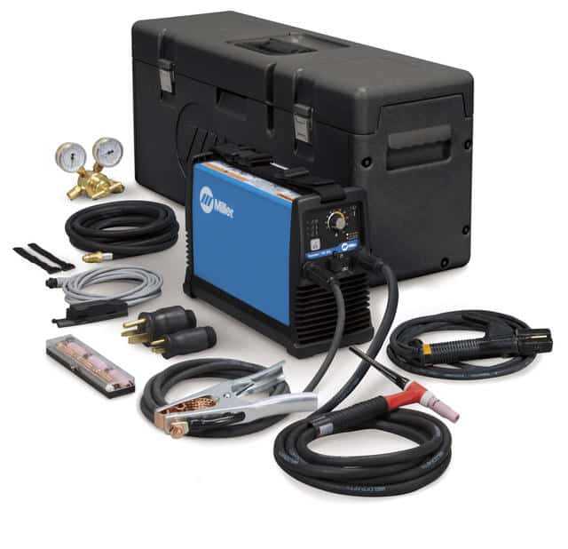
Regular upkeep is essential for ensuring optimal performance and longevity of your welding equipment. To maintain its efficiency, certain key components need periodic attention. These elements play a crucial role in the smooth operation and reliability of the machine. By understanding their function and knowing when to replace or service them, you can avoid costly repairs and downtime.
Air Filters: These are vital for keeping the internal mechanisms free from dirt and debris, allowing the system to operate without obstruction. Clean or replace them as needed to maintain airflow and prevent overheating.
Electrode Holders: Essential for proper arc control, these should be checked regularly for wear and tear. Damaged holders can affect weld quality and pose safety risks.
Cooling Fans: Efficient cooling is crucial for preventing the machine from overheating during extended use. Regular inspection and cleaning of cooling fans will help prevent performance issues.
Fuel Filters: These filters ensure that the fuel reaching the system is clean, minimizing the risk of contamination that could impair the engine’s functionality. Replacing them at regular intervals will keep the engine running smoothly.
Troubleshooting the Welding Machine Components
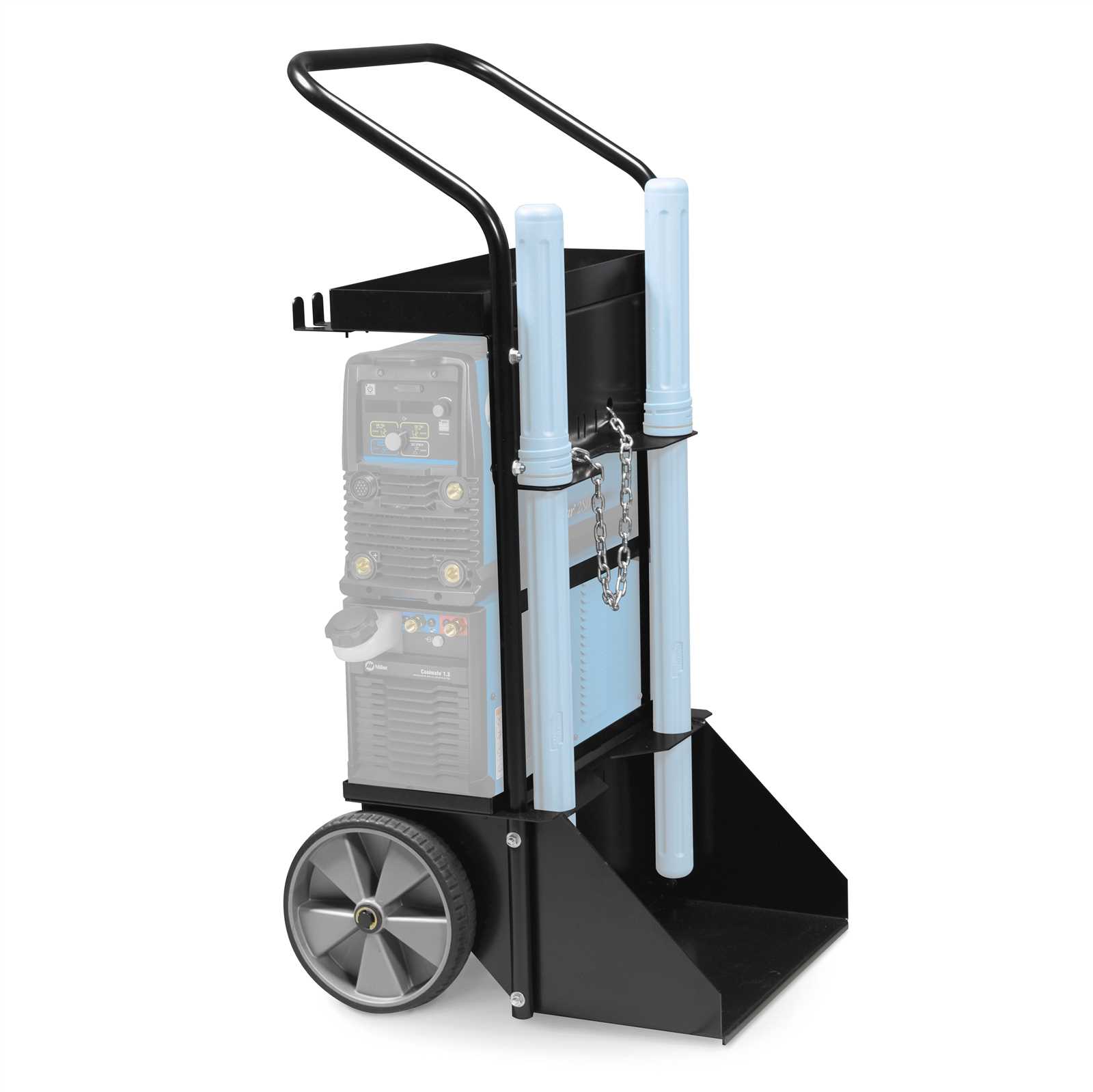
When dealing with issues in a welding device, identifying and fixing faulty elements is essential for ensuring smooth operation. Proper troubleshooting can help pinpoint malfunctioning components, allowing for a more efficient repair process. This section covers common challenges and solutions to help maintain optimal performance of your welding equipment.
Identifying Common Issues
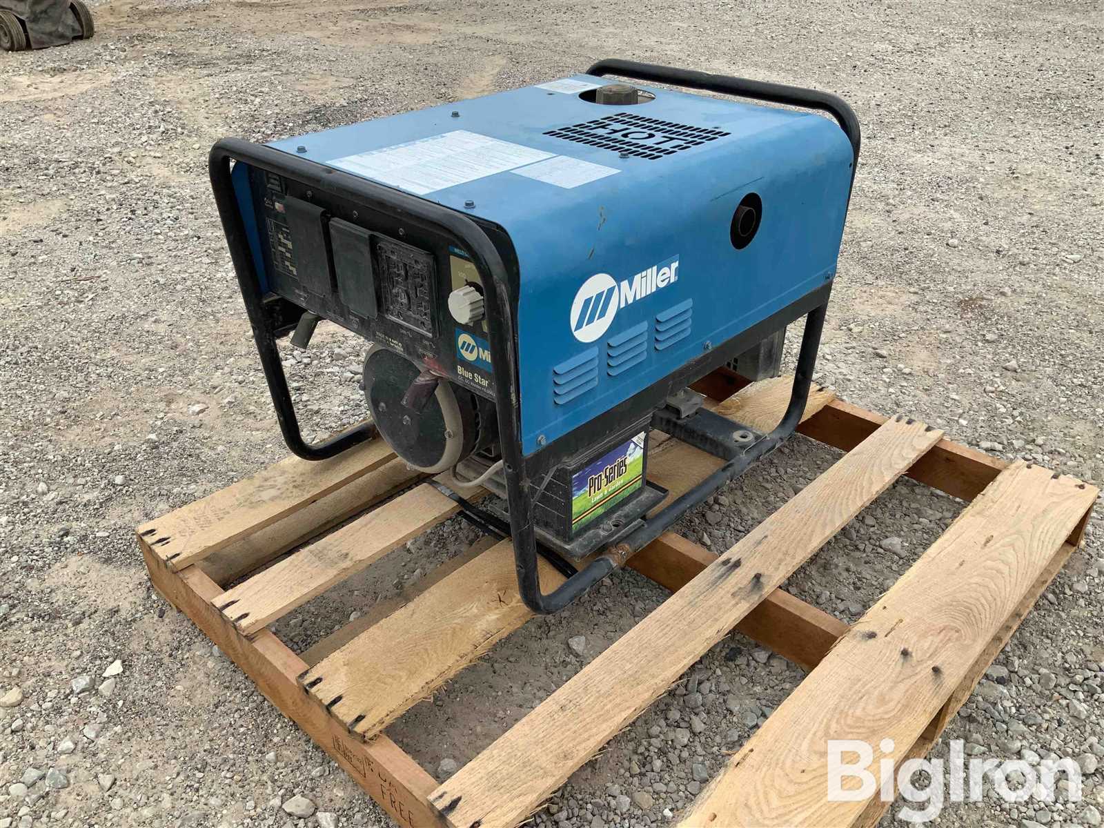
Many problems stem from wear and tear on specific internal and external components. Over time, connections may weaken, electrical elements can fail, or mechanical parts may break. A methodical approach can help identify these issues quickly and prevent further damage.
Key Troubleshooting Tips
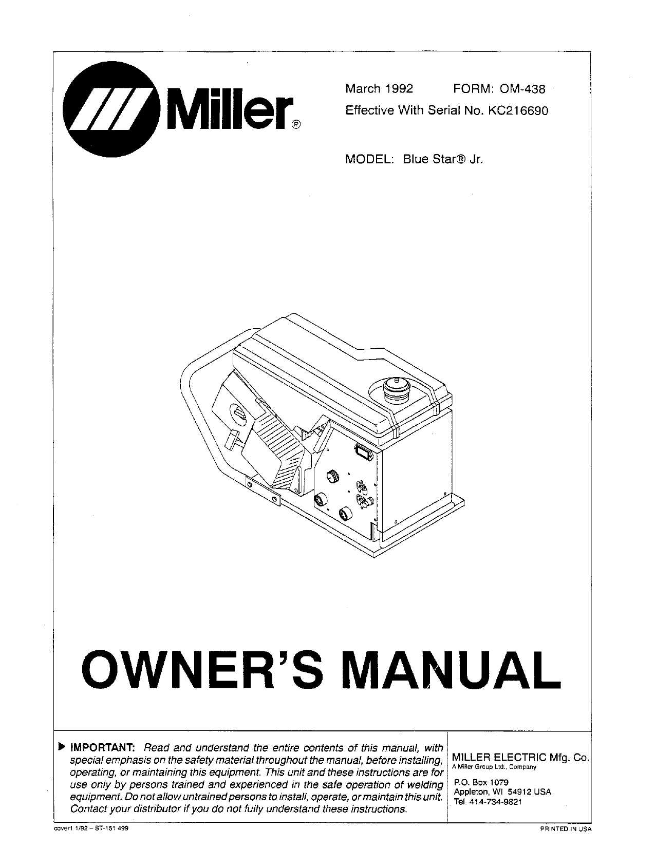
- Check electrical connections for signs of wear or corrosion.
- Inspect the power supply for adequate voltage and current flow.
- Ensure cooling systems are functioning properly to prevent overheating.
- Examine the wire feed mechanism for blockages or mechanical failure.
- Test the control systems and components for responsiveness.
Problem Possible Cause Solution Device not powering on Faulty power supply or connection Check connections, inspect power cord and fuse Inconsistent weld quality Electrode or wire feed problems Adjust feed rate, clean or replace electrode Excessive noise during operation Loose components or worn-out fans Tighten connections, lubricate moving parts Alternator and Generator Assembly Guide
Understanding the assembly of electrical power systems, such as alternators and generators, is essential for ensuring the reliable operation of your equipment. This guide covers the fundamental steps to correctly assemble these components, ensuring optimal performance and longevity. Following these instructions will help you avoid common pitfalls and maintain efficient power generation for your machinery.
Preparing the Components
Before starting the assembly process, gather all necessary components, including the housing, rotor, stator, and electrical connections. Ensuring that all parts are clean and in good condition is crucial for proper function. Inspect for any signs of wear or damage that could affect the overall performance of the system.
Assembly Steps
Begin by securing the rotor into the housing, making sure it is properly aligned. Next, position the stator around the rotor, ensuring it fits snugly within the designated space. Connect the electrical wiring, ensuring that each wire is securely attached and insulated to prevent shorts. Finally, test the assembly to confirm that the system is generating power effectively and efficiently.
Cooling System Diagram for Miller Welders
Understanding the cooling system is essential for maintaining the proper functioning of welding machines. This system ensures that the equipment remains at an optimal temperature during operation, preventing overheating and potential damage. A well-designed cooling process is crucial for extending the lifespan and improving performance during intensive tasks.
Key Components of the Cooling System
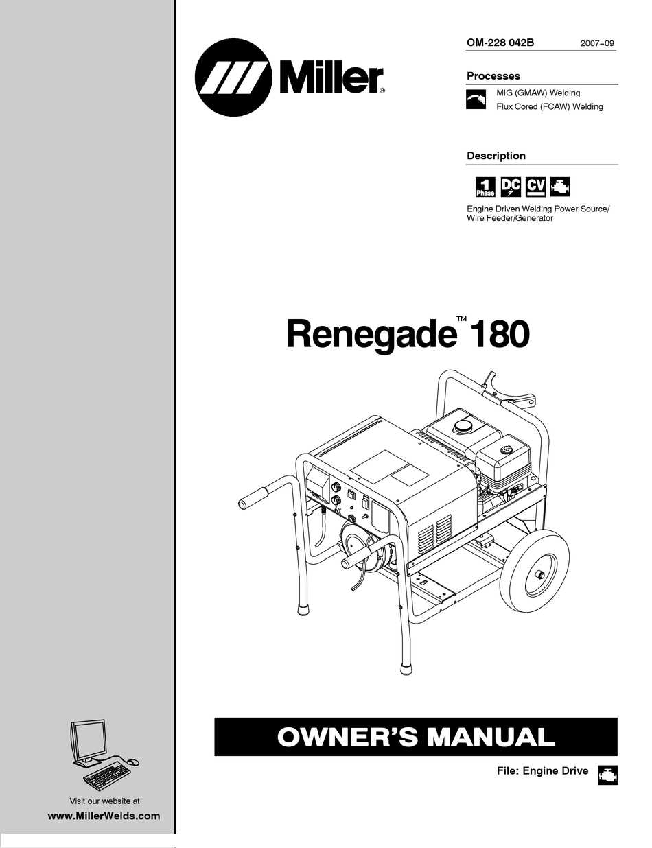
- Water pump – circulates coolant through the system.
- Cooling fan – maintains airflow around the unit to help with heat dissipation.
- Radiator – allows heat from the coolant to dissipate into the air.
- Coolant reservoir – stores and supplies coolant to the system.
- Hoses and pipes – transport coolant to various parts of the machine.
How the Cooling System Operates
The cooling system works by circulating a coolant throughout the machine. As the equipment operates, the coolant absorbs the heat generated by the internal components. The heated coolant is then passed through a radiator, where heat is released into the surrounding air. The coolant is subsequently recirculated, keeping the machine at a safe operating temperature.
Replacing Worn Components in the Welding Machine
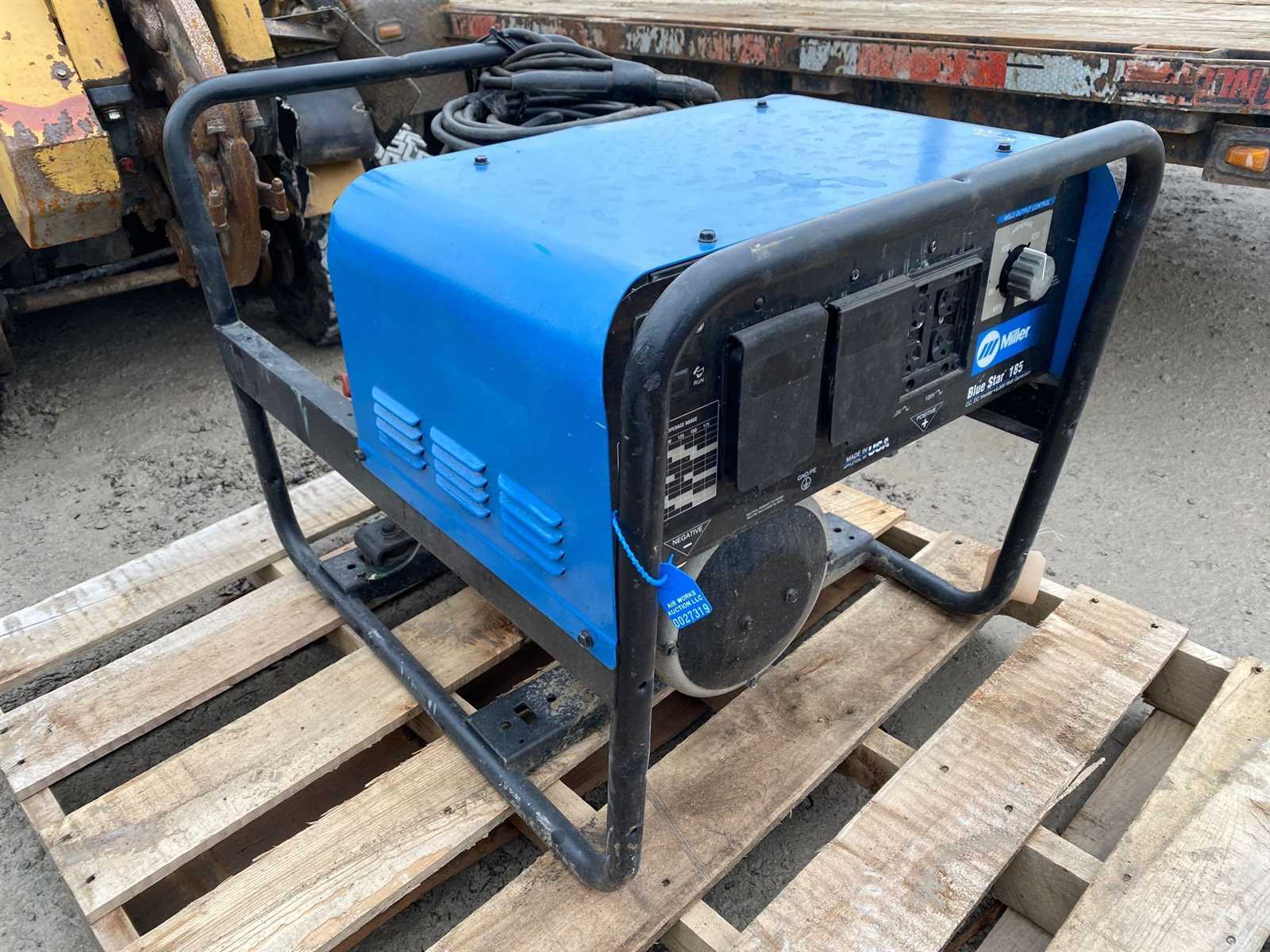
Maintaining optimal performance of your welding equipment is essential to ensure long-lasting operation. Over time, certain components can wear out, affecting the machine’s efficiency. Timely replacement of these worn-out parts is crucial to avoid costly repairs and downtime. Understanding the signs of component wear and knowing how to properly replace them can extend the life of your welder and keep it functioning at its best.
Identifying Key Components for Replacement
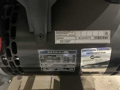
It’s important to regularly inspect the unit to detect any signs of wear. Some key elements prone to wear include the electrode holder, cables, and cooling system. These components endure a lot of stress during operation, making them susceptible to damage or degradation over time. Regular checks and routine maintenance can help you spot these issues early, ensuring you’re not caught off guard when your machine begins to underperform.
Steps to Replace Worn Components
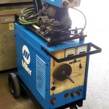
Once the worn components have been identified, the next step is to replace them carefully. Always refer to the equipment’s manual for specific instructions on the replacement procedure. Using high-quality replacement components ensures that the machine continues to operate at peak performance. Avoid using generic or substandard replacements, as they could lead to further issues or reduced efficiency.
Electrical System Breakdown of the Blue Star 185
The electrical system of this machine is designed to manage power distribution and ensure smooth operation under various conditions. This section explores the key components responsible for maintaining a stable energy flow and outlines their individual roles in the overall functioning of the device.