In the realm of electrical engineering, visual representations play a crucial role in conveying the intricate relationships between various components. These illustrations serve as essential guides, allowing individuals to navigate complex circuitry with clarity and precision. Each element within these visual frameworks contributes to the overall functionality and safety of the system.
Delving into the individual components reveals a wealth of information about their specific roles and interactions. From the flow of current to the protection mechanisms, each segment is meticulously designed to ensure efficient performance. Understanding these features is vital for anyone looking to grasp the fundamentals of electrical systems.
Moreover, comprehending how these individual sections integrate with one another enhances troubleshooting and maintenance efforts. A solid grasp of these connections not only fosters greater confidence but also empowers users to make informed decisions regarding repairs and modifications. Thus, a thorough exploration of these elements is indispensable for both professionals and enthusiasts alike.
Understanding Plug Diagrams

This section explores the intricacies of electrical connections, focusing on how various elements interact to ensure functionality and safety. Grasping these concepts is essential for anyone involved in electrical work or related fields.
Key components typically include:
- Conductors
- Insulators
- Connectors
- Grounding mechanisms
Familiarity with these elements allows individuals to:
- Diagnose issues effectively
- Enhance safety measures
- Optimize performance of electrical systems
Ultimately, understanding these connections leads to greater efficiency and reliability in electrical setups.
Essential Components of a Plug
The functionality of electrical connectors relies on several key elements that ensure safety and efficiency in their operation. These fundamental components work together to facilitate the transfer of power while minimizing risks associated with electrical usage.
Conductor: This is the metal component that allows electrical current to flow. Usually made of copper or aluminum, it is crucial for effective energy transmission.
Insulation: Surrounding the conductor, this protective layer prevents accidental contact and reduces the risk of short circuits. Materials like rubber or plastic are commonly employed for their durability and effectiveness.
Housing: The outer casing serves as a shield for the internal elements, providing both protection and structural integrity. It is typically made from tough materials that can withstand wear and tear.
Contacts: These metallic pieces connect the conductor to the electrical outlet, ensuring a reliable connection. Their design is vital for maintaining a secure fit and facilitating efficient energy transfer.
Locking Mechanism: This feature secures the connection, preventing accidental disconnection during use. It is essential for maintaining stability and ensuring safety in various applications.
How Current Flows Through a Plug
The movement of electrical energy through a connector is essential for powering various devices. Understanding this flow involves examining the route that electric charge takes from the source to the appliance, ensuring a seamless operation.
| Component | Function |
|---|---|
| Live Wire | Carries current from the power source to the device. |
| Neutral Wire | Returns current to the power source, completing the circuit. |
| Earth Wire | Provides a safe path for excess current, protecting users. |
The effective flow of electricity relies on the interaction between these elements, ensuring devices operate safely and efficiently.
Types of Electrical Plugs
Electrical connectors come in various designs, each tailored to specific regional standards and safety requirements. Understanding these variations is essential for ensuring compatibility and safe usage in different environments.
Type A is commonly found in North America and consists of two flat parallel pins. This configuration allows for straightforward insertion into compatible sockets. Its simplicity, however, limits grounding options, making it suitable for low-power devices.
Type C, also known as the Europlug, features two round pins and is widely used across Europe. This design supports a range of appliances and offers better grounding solutions, making it a versatile choice for travelers.
Type G, primarily used in the UK, includes three rectangular pins arranged in a triangular pattern. This configuration not only ensures a secure fit but also incorporates a fuse for added safety, making it ideal for high-power appliances.
Type I, used in Australia and New Zealand, has two flat pins in a V-shape along with a vertical grounding pin. This design enhances stability and safety, making it suitable for various household and industrial applications.
Each of these connectors serves distinct purposes, highlighting the importance of choosing the right type based on location and device requirements. Proper selection ensures efficient operation and minimizes the risk of electrical hazards.
Safety Features in Plug Designs
Ensuring user protection is paramount in electrical connectors. Various mechanisms are implemented to minimize risks associated with electric shocks and short circuits. These innovations contribute significantly to safe usage and enhance overall functionality.
Key Safety Mechanisms
Modern electrical connectors incorporate several essential safety features:
| Feature | Description |
|---|---|
| Shutter System | Prevents accidental contact with live parts when not in use. |
| Insulation | High-quality materials that prevent electrical leakage and ensure durability. |
| Grounding | Provides a safe path for excess current, reducing the risk of shock. |
Regulatory Standards
Adherence to strict safety regulations ensures that connectors meet high-quality standards, thus promoting reliability and user safety in various environments.
Common Plug Diagrams Explained
Understanding the various configurations used in electrical connections is essential for safe and efficient operation. These configurations provide crucial information about the arrangement of conductors and their respective functions. Grasping the differences among these layouts can enhance both practical skills and theoretical knowledge in the field of electrical engineering.
Standard Configurations are widely recognized and serve as the foundation for many electrical connections. Each design typically includes specific terminals for live, neutral, and ground connections, ensuring proper current flow and safety measures. Familiarity with these layouts allows users to identify the appropriate usage and compliance with safety standards.
Specialized Layouts cater to unique requirements or devices. These may feature additional pins or altered arrangements to accommodate specific functionalities. Understanding these variations is crucial for professionals who work with specialized equipment or installations, as they often dictate the compatibility of different components.
Visual References play an important role in learning about these configurations. Diagrams can simplify complex arrangements, allowing individuals to quickly comprehend the relationships between different terminals. Utilizing visual aids can significantly improve the understanding and application of these essential connections.
In summary, a thorough grasp of common arrangements and their unique characteristics is vital for anyone involved in electrical work. This knowledge not only promotes safety but also enhances the efficiency of various systems and devices.
Wiring Standards for Different Regions
Electrical configurations vary significantly across the globe, influenced by historical, technical, and safety considerations. Understanding these differences is crucial for ensuring compatibility and safety when connecting devices. Each region has adopted specific standards that dictate the design, dimensions, and functionality of electrical connectors and circuits.
Regional Variations
- North America: Typically follows the National Electrical Code (NEC), using NEMA standards for connectors.
- Europe: Adopts the International Electrotechnical Commission (IEC) standards, emphasizing safety and efficiency.
- Australia: Utilizes AS/NZS standards, which align closely with European regulations while incorporating local requirements.
- United Kingdom: Follows the British Standard (BS) 1363, known for its robust design and safety features.
Key Considerations
- Voltage and Frequency: Different regions operate on varying voltage levels and frequencies, affecting appliance compatibility.
- Safety Features: Many standards include specific safety mechanisms such as fuses, grounding, and insulation to prevent hazards.
- Connector Types: Each area employs distinct shapes and pin configurations, necessitating adapters for international travel.
Understanding these standards is vital for manufacturers, consumers, and travelers alike, ensuring safe and effective use of electrical equipment worldwide.
Identifying Male and Female Plugs
Understanding the distinctions between various connectors is essential for ensuring compatibility and safety in electrical systems. Each type serves a specific function and has unique characteristics that make it identifiable.
Characteristics of Male Connectors
Male connectors typically feature prongs or pins that protrude from the body, designed to fit into the corresponding receptacles. This design allows for a secure connection and effective transfer of electrical current.
Characteristics of Female Connectors
Conversely, female connectors contain openings or sockets that accommodate the prongs of male counterparts. This configuration enables a snug fit, ensuring a stable and reliable connection.
| Type | Design Features | Common Uses |
|---|---|---|
| Male | Protruding pins | Plugs for appliances, tools |
| Female | Socket openings | Receptacles, power strips |
Function of Each Pin in a Plug
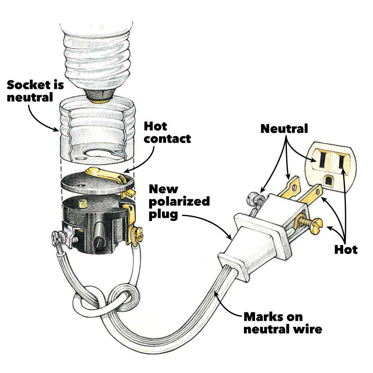
Understanding the roles of various connectors is essential for ensuring proper functionality and safety in electrical systems. Each terminal serves a specific purpose, facilitating the flow of electricity while maintaining the integrity of the entire system. This section delves into the distinct functions associated with each contact point, highlighting their importance in everyday usage.
Main Contacts
The primary terminals are crucial for transmitting power. Their design ensures efficient energy transfer, minimizing the risk of overheating or short circuits. Each contact is engineered to handle specific voltage and current levels, making them indispensable in various applications.
Safety is paramount in any electrical configuration. The grounding pin plays a vital role in protecting users from electric shock by providing a safe path for excess current. Additional safety features, such as insulation and proper alignment, are also critical to preventing accidents.
| Pin Number | Function |
|---|---|
| 1 | Live – Carries the current to the device |
| 2 | Neutral – Completes the circuit by returning current |
| 3 | Earth – Provides a safety ground |
Visualizing a Typical Plug Setup
This section aims to illustrate the essential components involved in a common electrical connection, offering insights into their arrangement and functionality.
- Connection Interface: The point where the electrical current enters.
- Safety Features: Mechanisms designed to prevent accidents.
- Conductors: Materials that allow electricity to flow efficiently.
Understanding these elements can enhance your grasp of how electrical systems operate.
- Identify the main entry point for electricity.
- Recognize the protective elements ensuring user safety.
- Learn about the materials that facilitate electrical conduction.
By exploring these aspects, you can delve deeper into the functionality of electrical connections.
Impact of Voltage on Plug Design
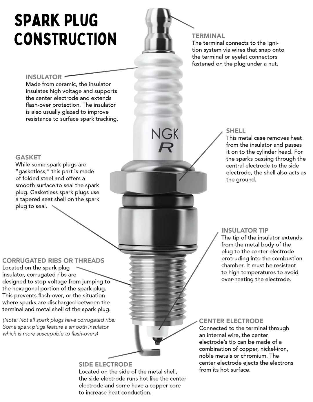
The level of electrical potential significantly influences the configuration and safety measures employed in connectors. Understanding how voltage affects these elements is crucial for ensuring reliable and safe connections in various applications.
Design Considerations
Higher voltage ratings necessitate specific design features to mitigate risks such as arcing and overheating. These features include reinforced insulation and improved contact materials to withstand elevated temperatures and electrical stress.
Safety Standards
Regulatory frameworks often dictate voltage-related specifications, ensuring that connectors are adequately designed for their intended use. Compliance with these standards is vital for minimizing hazards and enhancing user safety.
| Voltage Level (V) | Design Features | Safety Measures |
|---|---|---|
| Low (0-250) | Basic insulation | Standard safety mechanisms |
| Medium (251-600) | Enhanced insulation | Advanced thermal protection |
| High (601+) | Reinforced materials | Comprehensive safety protocols |
Maintenance Tips for Electrical Plugs
Ensuring the longevity and safety of your electrical connections requires regular care and attention. Simple maintenance practices can prevent potential hazards and enhance performance, making it essential to stay proactive in this area.
Regular Inspection: Check for signs of wear or damage periodically. Look for frayed wires, discoloration, or loose connections that may indicate a need for replacement.
Keep Dry: Moisture can be detrimental. Ensure that all connections are kept dry and away from damp environments to avoid corrosion and electrical faults.
Use Appropriate Tools: When making repairs or adjustments, always use tools designed for electrical work to ensure safety and effectiveness.
Proper Storage: When not in use, store your devices in a cool, dry place to prevent unnecessary wear and tear on their components.
By following these simple guidelines, you can help maintain the integrity of your electrical connections and ensure their reliable operation.