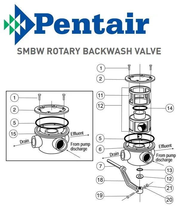
When dealing with intricate equipment, understanding how each element works together is essential for maintaining smooth operation. A clear overview of the essential components can provide valuable insights, helping to ensure optimal performance and longevity of your system.
Each element has a specific role, and recognizing how they interact allows for better troubleshooting and effective maintenance. Whether you’re looking to replace specific elements or simply aiming to extend the life of your equipment, a deeper understanding can make the process much more efficient.
By examining the internal structure and arrangement of these elements, you’ll be better equipped to handle any potential issues and ensure your system continues to operate at peak efficiency.
Overview and Functionality
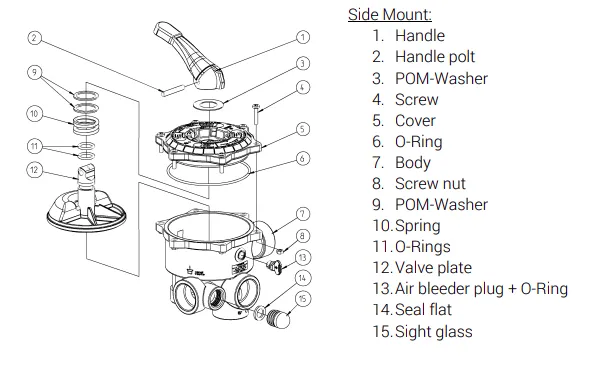
This system is designed to enhance the efficiency and reliability of water management solutions. Its advanced engineering allows it to handle multiple operational demands, ensuring smooth and consistent performance in various environments. The unit integrates essential features to support its functions, making it an ideal choice for those seeking durable and effective water control solutions.
The functionality of the system focuses on regulating water flow with precision and stability. It offers flexibility in installation and maintenance, contributing to long-term usability. This model’s design prioritizes user-friendly operation, ensuring that it can be easily integrated into both residential and commercial settings.
Key Components of the SM-20-3 System
The system is comprised of several essential elements, each playing a crucial role in its functionality. These components are designed to work in harmony, ensuring efficient operation and reliability. Understanding the purpose and interaction of these elements helps in maintaining and troubleshooting the system effectively.
Pump Assembly: This is responsible for moving fluids through the system, ensuring consistent flow and pressure. It is engineered to handle varying operational demands, providing the necessary force for smooth circulation.
Control Unit: The brain of the system, managing the coordination of different functions. It monitors performance, adjusts settings, and ensures all other parts operate within optimal parameters.
Filtration Mechanism: Ensures that any impurities or unwanted particles are effectively removed, maintaining the purity of the medium passing through. This contributes to both the longevity of the system and the quality of its output.
Valves and Connectors: These elements regulate the flow direction and maintain secure connections within the system, preventing leaks and ensuring consistent performance. Their quality and condition are key
Understanding the Layout of the Visual Guide for SM-20-3
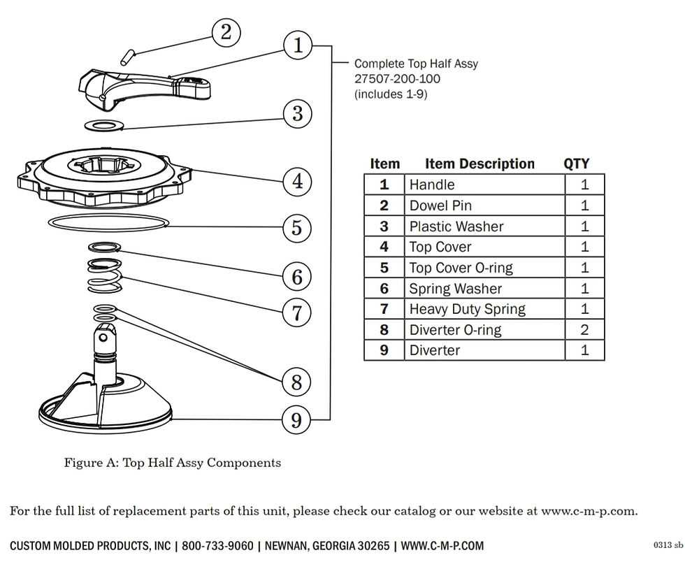
In this section, we delve into the structure and organization of the visual guide associated with the SM-20-3 model. The visual aid serves as a comprehensive map, detailing the various components and their interconnections within the system.
Key Components Overview
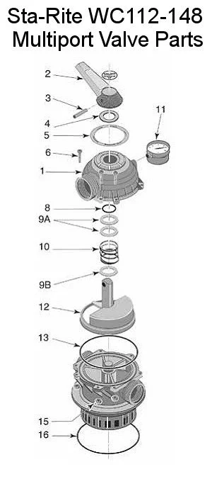
The guide outlines essential elements critical to understanding the functionality and assembly of the SM-20-3 unit. It illustrates key parts, highlighting their roles in the overall operation, without delving into specific names or technical jargon.
Interpreting Relationships and Pathways
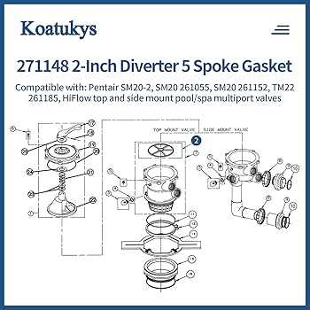
Moreover, the visual representation elucidates relationships and pathways, presenting a clear picture of how components interact and contribute to the system’s performance. This aids in troubleshooting and maintenance by visualizing the flow and integration of parts.
Guide to Identifying Key Components of SM-20-3 Model
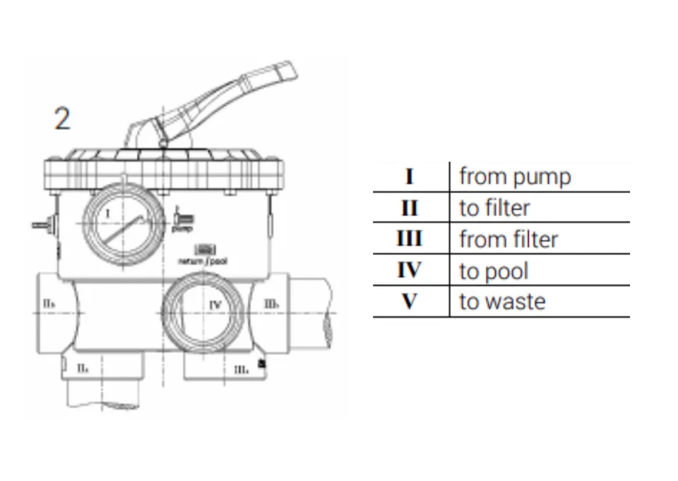
Understanding the essential elements of this model is crucial for effective maintenance and operation. By recognizing the individual components, you can ensure proper functioning and timely replacement when necessary. This guide will help you pinpoint the most important elements and their functions within the system.
- Main Housing: The central structure that holds the various elements in place, providing stability and protection.
- Filtration Unit: A vital section responsible for ensuring clean and smooth operation by filtering unwanted debris.
- Valve Assembly: Regulates the flow of liquids and maintains the internal pressure for optimal performance.
- O-Ring Seals: These small but crucial seals prevent leaks and maintain airtight connections between sections.
- Seals and gaskets are frequently swapped out to address leaks or to restore proper sealing functionality.
- Valves may need to be exchanged when they become faulty or fail to control water flow accurately.
- O-rings, often exposed to wear, are another common item that should be changed during system inspections.
- Clamps and connectors are also checked regularly and replaced if they show signs of corrosion or breakage.
- Assess the environment where the equipment will be set up to ensure compatibility with local conditions.
- Review all necessary components and tools required for the installation process.
- Follow the manufacturer’s recommendations for positioning and securing each element to optimize functionality.
Common Replacement Parts for Pentair SM-20-3
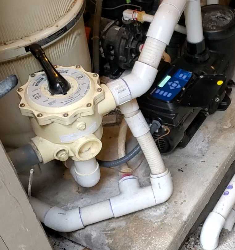
Many components in water systems can experience wear and may require substitution over time to ensure efficient operation. Regular maintenance often involves identifying which pieces are prone to damage or deterioration and replacing them promptly to prevent larger issues.
By ensuring timely substitution of these critical elements, you can extend the lifespan and performance of your water management setup.
Understanding the Components Breakdown
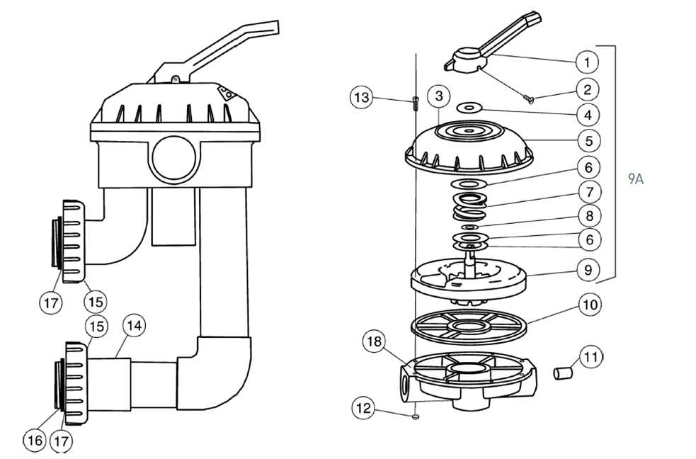
In this section, we will delve into deciphering the schematic illustration showcasing the various components of the SM-20-3 equipment. The visual representation offers a comprehensive view of the different elements that constitute this machinery.
Identifying Key Parts
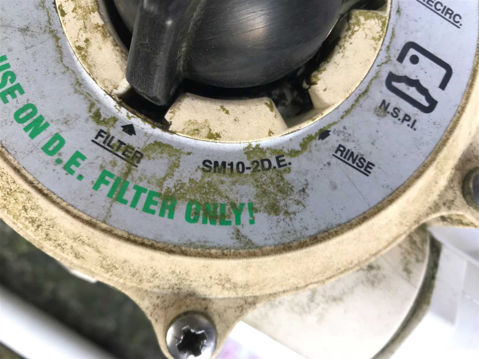
The diagram categorizes the crucial elements into identifiable sections, each serving a specific function within the operational framework of the device. By understanding the role of each part, users gain insights into its overall functionality.
| Section | Description |
|---|---|
| 1 | Primary unit housing major components |
| 2 | Secondary module containing supplementary parts |
| 3 | Connectivity elements linking various sections |
Maintenance Tips for Key Components
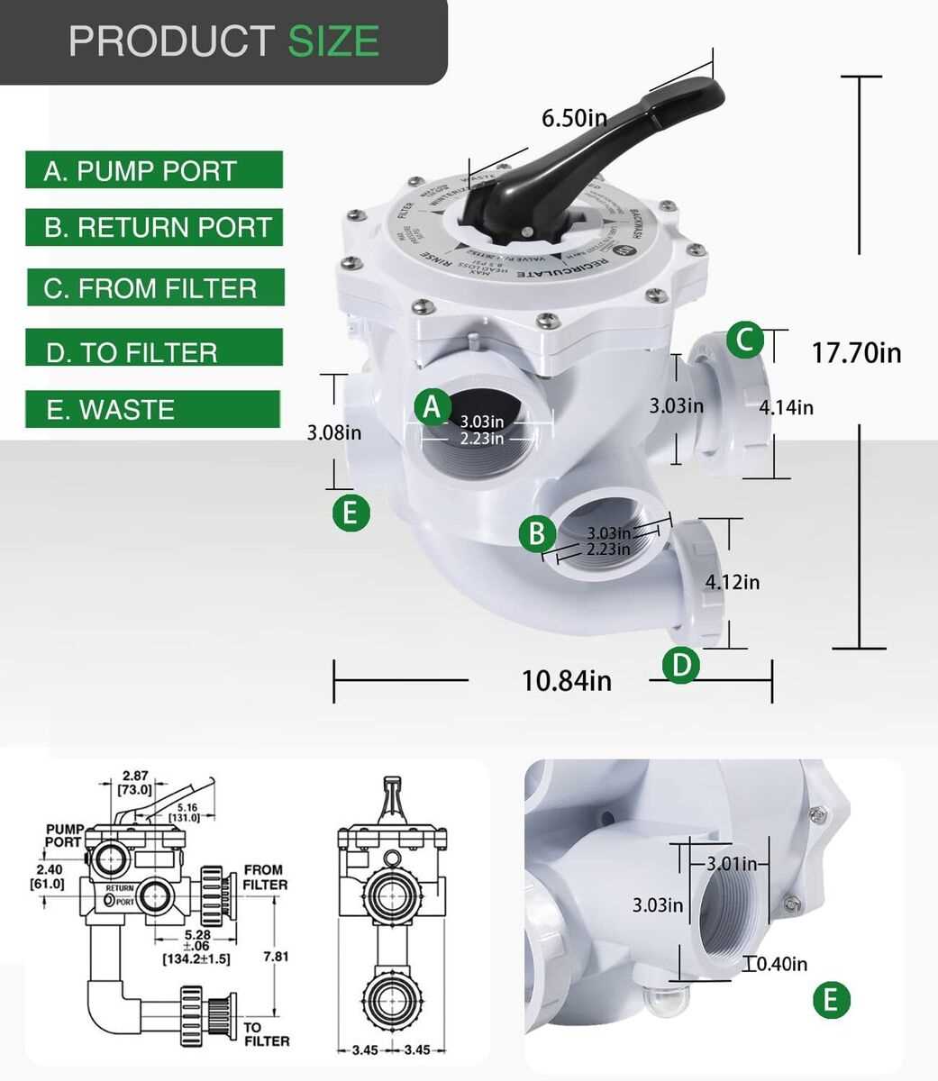
Regular upkeep of your system’s essential components ensures long-term efficiency and smooth operation. Proper care not only extends the lifespan of individual elements but also prevents potential issues from escalating, saving time and resources in the long run.
| Component | Maintenance Tip |
|---|---|
| Filtration Unit | Clean or replace the filter regularly to maintain optimal flow and prevent blockages. |
| Valves | Inspect for leaks and ensure all seals and gaskets are intact to prevent pressure loss. |
| Piping Connections | Tighten loose connections and check for any signs of wear or corrosion to avoid leaks. |
| Electrical Controls | Periodically check wiring and connections for any signs of damage or wear to ensure proper operation. |
Exploring the Inner Workings of the SM-20-3
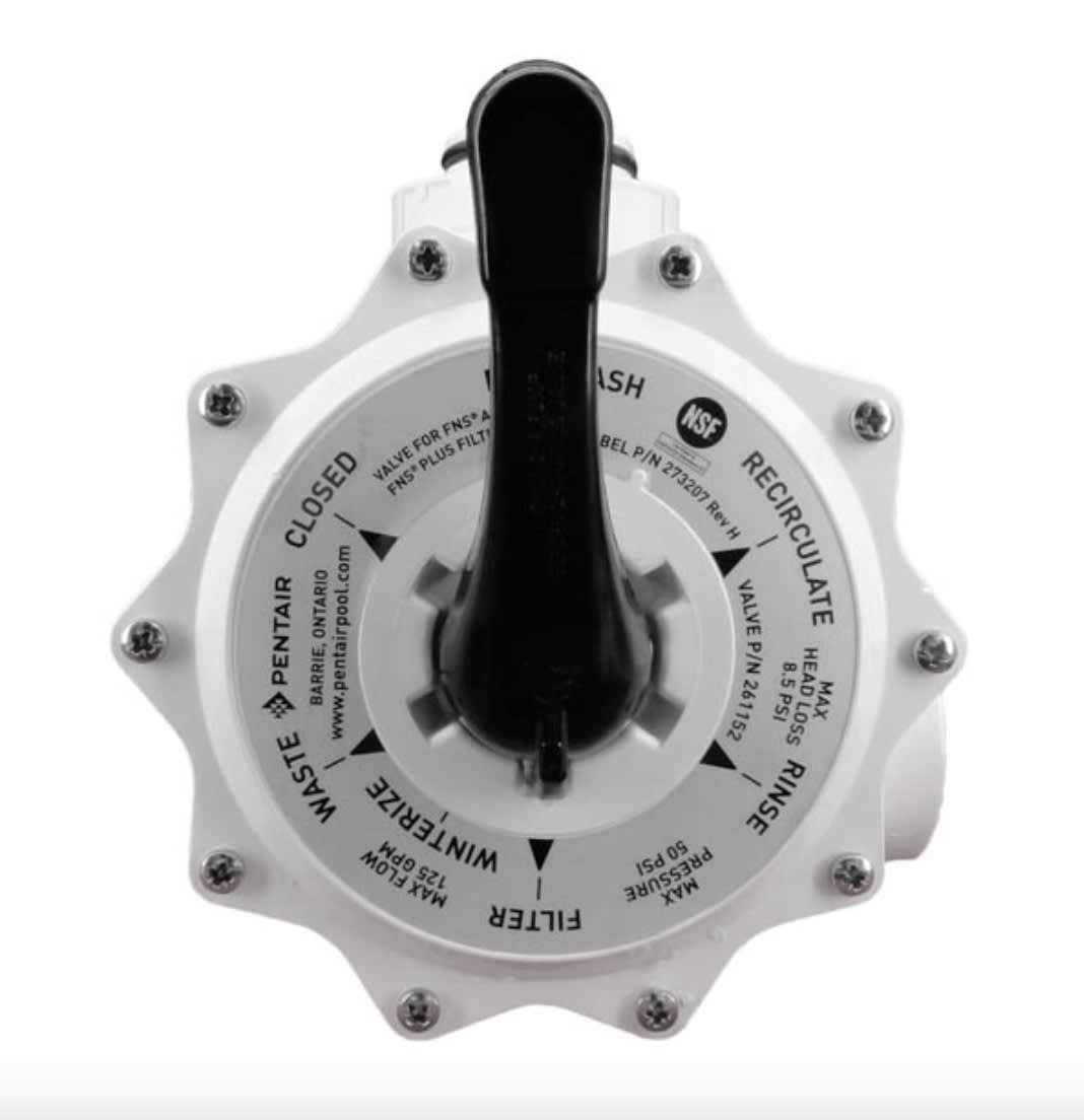
The intricate design of this mechanical device plays a crucial role in its overall functionality. Understanding how its components interact provides valuable insights into the efficiency and reliability of the system. Each element contributes uniquely to the performance, ensuring that the unit operates smoothly under various conditions.
Delving into the core elements reveals the significance of each section. For instance, the mechanisms responsible for fluid dynamics are essential in maintaining optimal flow rates. Additionally, the arrangement of various components enhances the device’s ability to adapt to changes in demand, showcasing its versatility.
By examining the interactions between these parts, one can appreciate the engineering principles that govern its operation. This knowledge not only aids in troubleshooting and maintenance but also fosters a deeper understanding of the overall technology behind such devices.
Installation Insights for SM-20-3 Parts
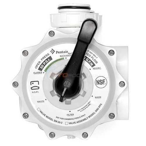
Understanding the nuances of assembly and configuration for specific components can significantly enhance operational efficiency. This section delves into key considerations and practical steps essential for successful installation.
Proper alignment and secure connections are vital to prevent potential issues during operation. Paying attention to these details can extend the lifespan of the system and enhance performance.
- Start by preparing the installation area, ensuring it is clean and free from obstructions.
- Gather all necessary components and check for any damages or discrepancies before beginning.
- Carefully follow the installation instructions to ensure each part is placed correctly.
- Once assembled, conduct a thorough inspection to confirm everything is secure and aligned as intended.
Following these guidelines can lead to a smooth installation process, ensuring that the system operates reliably and efficiently.
Troubleshooting Issues Using the Parts Diagram
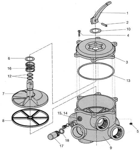
Identifying and resolving problems with equipment can often be a challenging task. Utilizing a visual representation of components can significantly aid in diagnosing issues effectively. This method allows users to pinpoint specific elements and understand their functions within the system, streamlining the troubleshooting process.
When encountering malfunctions, start by reviewing the visual reference to familiarize yourself with each component’s layout. Pay attention to any signs of wear or damage that may affect performance. If a particular part appears compromised, consider replacing it to restore optimal functionality.
Additionally, cross-reference the visual guide with operational symptoms. For instance, if the equipment is making unusual noises, consult the representation to identify the source of the sound. This targeted approach can save time and prevent unnecessary replacements of unaffected parts.
By systematically analyzing each element in relation to the overall system, users can effectively troubleshoot and maintain their equipment, ensuring longevity and reliable operation.