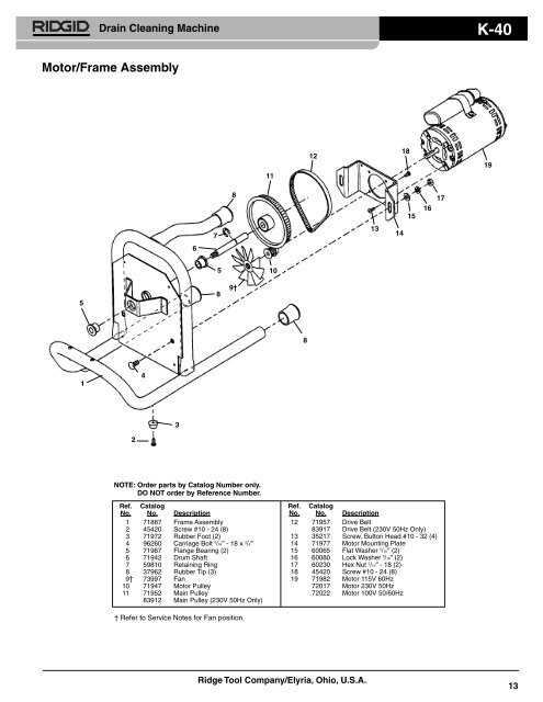
Understanding the internal structure of various devices is essential for effective maintenance and repairs. Detailed breakdowns of essential components offer a clear view of how different parts work together, ensuring smooth operation and longer lifespan. By exploring the layout of each element, users can easily identify potential issues or plan for routine servicing.
Whether you’re handling regular upkeep or troubleshooting malfunctions, having a clear visual representation of each component’s location helps simplify the process. This guide aims to provide a thorough exploration of the various sections, offering insight into the role each element plays within the system.
With this information, users will be better equipped to address technical challenges, improving both the efficiency and safety of their equipment. This approach fosters confidence in performing repairs and adjustments, ensuring a longer operational life.
Understanding the Ridgid Parts Diagram
When maintaining or repairing equipment, it’s essential to have a clear overview of all components and their functions. A detailed chart offers a complete view of the elements involved in the construction of a tool, making it easier to identify the source of issues or locate specific elements. Whether you’re assembling, troubleshooting, or simply maintaining your tools, these illustrations provide a structured guide to help you proceed efficiently.
How to Use the Visual Breakdown
The breakdown of tool components is designed to be user-friendly, allowing you to see how each piece connects and interacts. By following the logical flow of the image, you can pinpoint areas that need attention and quickly access the necessary pieces for repair or replacement.
Benefits of a Component Overview
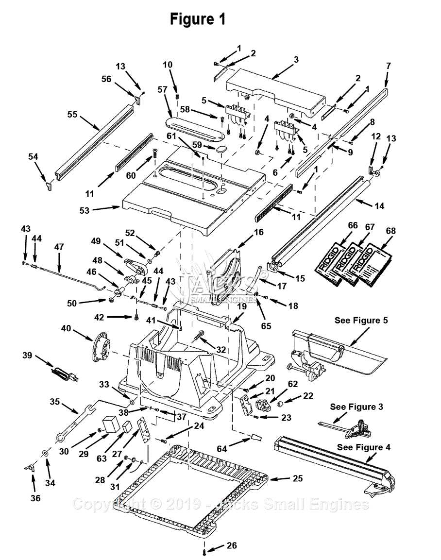
This type of schematic helps reduce guesswork by visually representing the entire tool. It also enhances accuracy, ensuring that each part is installed or removed correctly, which in turn extends the lifespan of the equipment and minimizes the chances of errors during repairs.
Key Components of Ridgid Tools
The essential elements that make up professional-grade tools are designed to ensure longevity, performance, and user efficiency. These units are carefully engineered to provide the optimal balance between durability and functionality, making them reliable for various demanding tasks. The design of each piece ensures that the tools remain easy to use while maintaining high standards of precision.
Motor and Power Mechanism play a vital role in ensuring the tool operates efficiently, delivering the necessary force for different applications. The sturdy casing offers protection against wear and tear, safeguarding internal systems from damage.
The ergonomic handle allows users to maintain a firm grip, reducing fatigue during prolonged use. Meanwhile, the cutting edges or blades are crafted to stay sharp for longer periods, minimizing maintenance needs.
Additionally, the adjustable settings let users customize the tool for specific tasks, ensuring accuracy in every operation. These features work together seamlessly, enhancing the overall functionality of each unit.
How to Read a Ridgid Parts Diagram
Understanding a schematic layout of equipment is essential for efficient maintenance or repairs. A well-structured visual guide helps identify components, their relationships, and the sequence in which they should be assembled or disassembled. This section provides insights into interpreting such layouts, ensuring you can easily navigate through the visual representation of mechanical assemblies.
Identifying Key Components
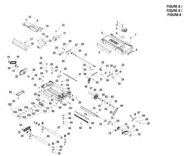
The first step in reading the visual layout is recognizing the major elements. Typically, each component is labeled with a number or symbol. These references correspond to an index, providing more details about each element. By locating these key elements first, you can form a mental image of how everything fits together.
Understanding Assembly Flow
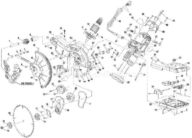
The visual guide often shows the relationship between different parts through lines, arrows, or sequencing markers. These indicate how elements connect or interact. Focus on these markers to understand the order of operations, which will guide you through assembly or disassembly processes efficiently.
Benefits of Using a Parts Diagram
Visual guides are an essential tool for anyone working with mechanical systems. They provide a clear and structured way to understand the assembly and functionality of various components, making the process of repairs or maintenance more efficient and less error-prone.
Enhanced Understanding of Components
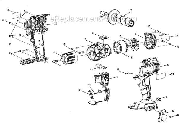
By using these visual tools, users can quickly identify how individual elements fit together, ensuring a smoother assembly process. This prevents common mistakes and helps in recognizing the proper alignment of each piece.
- Easy identification of parts and their placement
- Improved accuracy during assembly
- Reduces the time spent on troubleshooting
Streamlined Maintenance Process
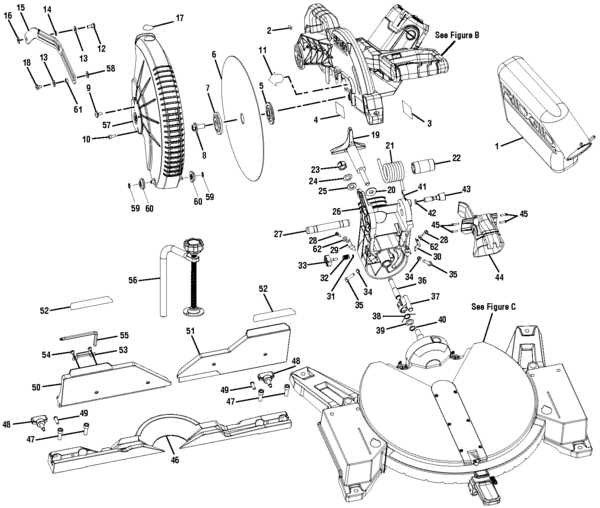
These diagrams also aid in planning regular upkeep. With the visual reference, users can easily spot which elements need attention, making maintenance schedules more efficient.
- Helps in predicting wear and tear
- Simplifies ordering of replacement components
- Increases the lifespan of equipment
Commonly Replaced Ridgid Tool Parts
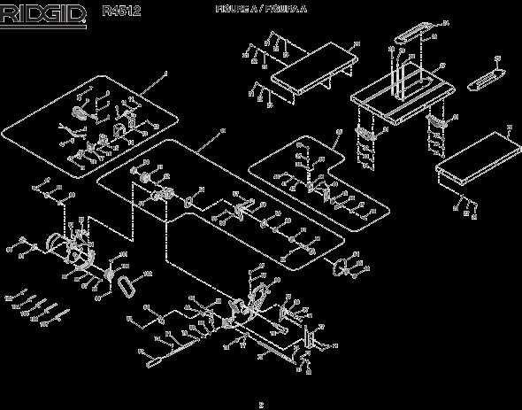
Power tools are essential for various tasks, and over time, certain components tend to wear out or need replacement to ensure the tool operates efficiently. Regular maintenance and timely updates of these elements can extend the life of your equipment and maintain its performance at a high level.
Below is a list of frequently replaced components for power tools, highlighting key elements that often require attention:
| Component | Function |
|---|---|
| Carbon Brushes | Ensure continuous electrical contact for motor operation |
| Switches | Control the tool’s power and operational settings |
| Batteries | Provide portable power for cordless tools |
| Drive Belts | Transmit power between motor and working components |
| Blade Guards | Protect the user from moving parts during operation |
Locating Specific Parts in the Diagram
Finding particular components in an illustration can significantly enhance your understanding and efficiency when working on a project. This section aims to provide guidance on how to effectively identify and navigate various elements within the visual representation.
Understanding the Key Elements
Familiarizing yourself with the primary features of the illustration is essential. Each section typically includes labels, numbers, or colors that correspond to different items, making it easier to pinpoint what you need. Utilizing a reference guide can also help clarify any confusing parts of the image.
Using a Reference Table
A reference table can be a valuable tool when locating specific items. Below is a sample table that illustrates how to organize and reference various components:
| Item Number | Description | Location |
|---|---|---|
| 1 | Main Housing | Top Left Corner |
| 2 | Control Switch | Middle Right Section |
| 3 | Power Supply | Bottom Center |
Using a combination of visual cues and reference materials will facilitate a more efficient search for the desired items in the illustration.
Exploring Different Ridgid Models
Understanding the various models offered by the brand can enhance your selection process when it comes to tools and equipment. Each version features unique characteristics tailored to specific tasks, making it essential to recognize their differences.
Here are some key aspects to consider when examining different models:
- Performance: Evaluate the efficiency and power each variant delivers.
- Durability: Consider the materials used in construction that affect longevity.
- Compatibility: Check for accessories and components that may be compatible with other equipment.
- Features: Look for specialized functions that can improve usability.
Whether you’re a professional or a DIY enthusiast, selecting the right model can significantly impact your productivity and success in various projects.
Identifying Part Numbers and Descriptions
Understanding the identification of components is essential for effective maintenance and repair. Recognizing the correct codes and specifications enables users to procure the right items efficiently, ensuring the longevity and performance of equipment. Accurate identification helps avoid errors that may arise from using incorrect or incompatible pieces.
Common Identifiers
Component identifiers typically include a series of numbers and letters that convey essential details about the item. These codes can indicate size, material, and function, making them vital for users seeking replacements. Familiarity with these identifiers enhances the ability to find suitable alternatives quickly.
Descriptive Information
In addition to numerical codes, descriptions provide valuable context regarding the function and compatibility of each item. Clear and concise descriptions facilitate better understanding and help users select the appropriate components for their specific needs. Engaging with detailed information aids in making informed decisions during procurement.
Maintenance Tips Using a Parts Diagram
Understanding the layout of components is crucial for effective upkeep of your equipment. A visual reference can greatly enhance your ability to identify various sections and elements, ensuring a smoother maintenance process. Here are some valuable suggestions to help you utilize a schematic effectively.
Identifying Key Components
Before diving into maintenance, familiarize yourself with the main elements shown in the schematic. This can help you understand how different parts interact and the overall structure of your equipment.
- Study the key symbols and labels to recognize each part’s function.
- Note any common wear points that may require extra attention during inspections.
- Pay attention to assembly and disassembly instructions that guide you through maintenance tasks.
Regular Inspection and Upkeep
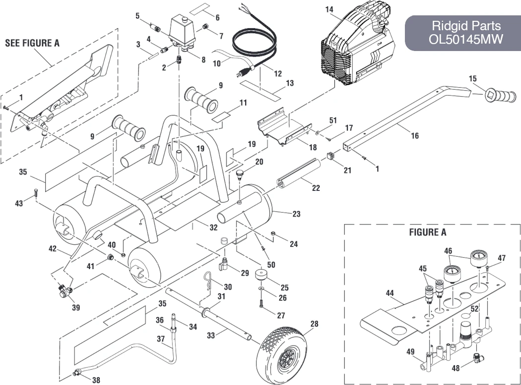
Establish a routine for checking components based on your reference material. Regular evaluations can prevent minor issues from escalating into major problems.
- Schedule periodic checks to clean and lubricate moving parts.
- Replace any worn-out or damaged elements as indicated in the schematic.
- Document any changes or repairs for future reference and to track performance over time.
Ordering Replacement Parts Efficiently
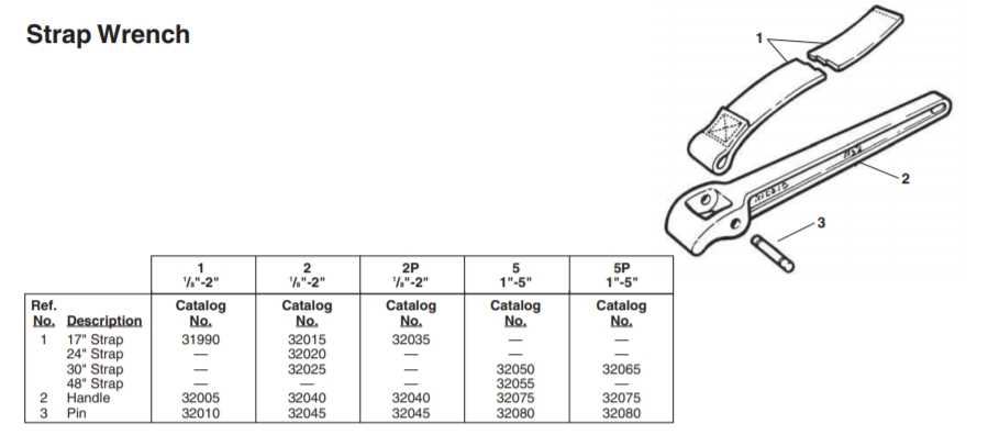
When it comes to maintaining tools and equipment, ensuring you have the right components available is crucial. Streamlining the process of acquiring these necessary items can save time and reduce frustration. Understanding the best practices for obtaining replacements can lead to a more effective maintenance routine.
Identifying Needed Components
Before placing an order, it’s essential to accurately identify what is required. This can involve checking manuals, consulting diagrams, or contacting customer support to clarify specifications. A precise understanding of the items you need helps prevent errors and delays.
Choosing a Supplier
Selecting a reliable supplier is just as important as identifying the correct components. Look for vendors who offer comprehensive catalogs, competitive pricing, and good customer service. This can make the ordering process smoother and more efficient.
| Supplier | Contact Method | Delivery Time | Return Policy |
|---|---|---|---|
| Supplier A | Email, Phone | 2-3 days | 30 days |
| Supplier B | Website | 1 week | 15 days |
| Supplier C | Phone | 3-5 days | 30 days |
Diagram Updates for New Ridgid Models
In response to advancements in technology and user feedback, manufacturers have implemented significant revisions to visual representations associated with their latest offerings. These updates aim to enhance user experience by providing clearer insights into the components and functionalities of newer models. Such changes facilitate easier identification of individual parts and streamline the maintenance process.
Importance of Accurate Visual References
Accurate visual references are crucial for ensuring efficient repairs and maintenance. With the latest updates, users can benefit from enhanced clarity and detail, which simplifies troubleshooting and part replacement. This approach not only saves time but also minimizes the risk of errors during assembly or repair tasks.
Overview of Recent Modifications
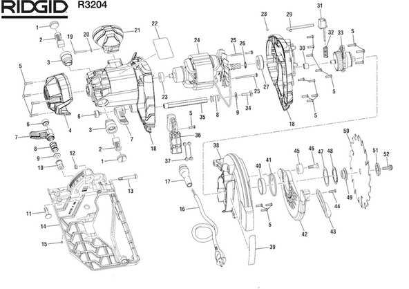
Here is a summary of the recent modifications made to visual references for newer models:
| Model | Update Type | Description |
|---|---|---|
| Model A | Enhanced Detail | Increased clarity of component layouts for easier identification. |
| Model B | Color Coding | Introduced color coding for quick reference of key parts. |
| Model C | 3D Visuals | Added 3D representations to provide a comprehensive view of assemblies. |