Transfers the rotational force from
Exploring the Steering Mechanism
The steering system plays a crucial role in providing directional control and maneuverability. Understanding how it operates can help in diagnosing issues and maintaining overall performance. By examining the components involved in turning the wheels, we gain insight into the coordination between the operator’s input and the vehicle’s response on various terrains.
Key elements within this system work together to ensure smooth and precise control. From the rotational motion at the handle to the complex linkages that transfer force to the wheels, each part is vital. Regular inspection of these components can prevent wear and tear, ensuring reliability and safety during operation.
Optimizing the alignment and maintenance of these elements is essential for enhancing stability and ease of use, especially when navigating tight spaces or uneven surfaces. A well-maintained system not only improves steering precision but also extends the lifespan of the equipment.
Chassis Components Overview
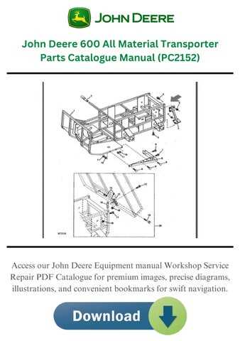
The foundation of any machine lies in the frame, which houses essential elements for stability and functionality. This structure supports various mechanical systems, providing the necessary integrity for the operation and movement of the entire unit. Understanding the key elements that comprise this framework is crucial for maintenance and troubleshooting, ensuring optimal performance and durability.
Key Structural Elements
The primary structural components include the base, side rails, and cross members. These elements work together to form a solid and stable platform, crucial for housing additional parts such as the engine, transmission, and other integral systems. Each part is designed to withstand various stresses and ensure smooth operation under different conditions.
Connection and Support Systems

In addition to the core framework, various support systems are integrated, such as mounting brackets, suspension elements, and reinforcement bars. These components ensure proper alignment, reduce vibration, and provide support for additional machinery and load-bearing functions. Their role is vital in maintaining the overall structural integrity and performance of the system.
| Component |
Description |
| Base |
Provides the foundation and primary support for the machine’s structure. |
| Side Rails |
Helps in maintaining structural alignment while withstanding external forces. |
| Cross Members |
Offers additional stability, preventing flexing and deformation under pressure. |
| Mounting Brackets |
Secures components in place, ensuring they remain fixed during operation. |
Blade Assembly and Cutting Mechanism
The cutting mechanism is essential for achieving a clean and efficient trimming process. This assembly is designed to work seamlessly with the rest of the machine, ensuring smooth performance while maintaining high durability. The interaction between the blade and its components allows for precise cutting, making it ideal for regular use in various environments.
The blade itself is made from strong materials, optimized for sharpness and longevity. It is securely mounted within the assembly to minimize vibrations and enhance control during operation. The cutting action is powered by a motor that drives the blade, ensuring consistent and uniform results across different types of surfaces.
Additionally, the positioning of the blade is key to the mechanism’s efficiency. With careful alignment and design, it can tackle a wide range of tasks, from light trimming to more intensive cutting, with minimal maintenance required. The overall structure allows for easy adjustments, enabling users to tailor the performance according to their specific needs.
Transmission System Essentials
The transmission mechanism in a machine is a vital component that enables the transfer of power from the engine to the wheels or other moving parts. This system ensures that the device operates efficiently and can handle varying loads and speeds. Understanding its key elements is crucial for proper maintenance and optimal performance.
Key elements of a typical transmission system include:
- Gears and Gearboxes: These are responsible for controlling the speed and torque by adjusting the gear ratios.
- Clutch Mechanism: Allows for smooth engagement and disengagement of gears, preventing engine strain.
- Drive Shafts: Transmit power from the gearbox to the wheels or other components requiring motion.
- Lubrication System: Keeps all moving parts well-oiled to minimize wear and tear, ensuring smooth operation.
- Control Cables or Linkages: These components are responsible for selecting gears and controlling the transmission system remotely.
Regular inspection of these components ensures the longevity and efficiency of the entire system, reducing the likelihood of costly repairs.
Seat and Control Panel Layout
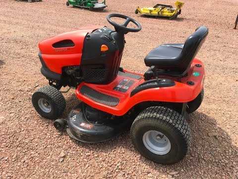
The arrangement of the seating area and the control interface plays a critical role in the overall usability of the equipment. The design ensures that the operator can comfortably control various functions while maintaining proper posture and accessibility. A well-structured layout provides intuitive placement of key elements, allowing for seamless operation in different environments.
Seat Positioning
The positioning of the seat is carefully designed to support the user’s comfort and ergonomic needs. The height, tilt, and distance from the control panel are adjustable, offering a customizable experience. This feature is essential for users who spend long hours operating the machine, as it reduces fatigue and promotes efficiency.
Control Interface Design
Positioned in close proximity to the seat, the control panel ensures that all necessary functions are within easy reach. The arrangement of buttons, levers, and switches is intuitive, providing quick access to essential controls. Clear labeling and strategic placement reduce the risk of errors and enhance the overall user experience.
Maintenance and Replacement Guide
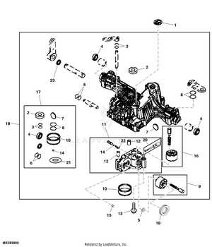
Proper upkeep and timely part replacement are essential for ensuring the longevity and optimal performance of your equipment. Regular checks and following a structured maintenance plan can help prevent unexpected breakdowns and improve efficiency. This guide outlines key areas to focus on and offers practical steps to ensure smooth operation.
Routine Maintenance Tasks
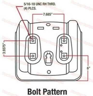
- Check moving components regularly for wear and tear.
- Lubricate parts as per manufacturer guidelines to reduce friction.
- Inspect electrical connections for corrosion or loose fittings.
- Clean air filters and cooling systems to prevent overheating.
Part Replacement Recommendations
- Replace worn-out belts or chains that show signs of damage.
- Use only compatible components to maintain system integrity.
- Ensure proper installation of new parts to avoid functional issues.
- Test the equipment after replacing parts to confirm correct operation.
Troubleshooting Common Mechanical Issues
Mechanical failures are inevitable in any complex system, and recognizing typical problems early can save time and effort. Understanding how each component functions together allows for a more efficient approach to fixing common issues. This section focuses on identifying frequent malfunctions and providing solutions for swift repairs.
Identifying Unusual Sounds
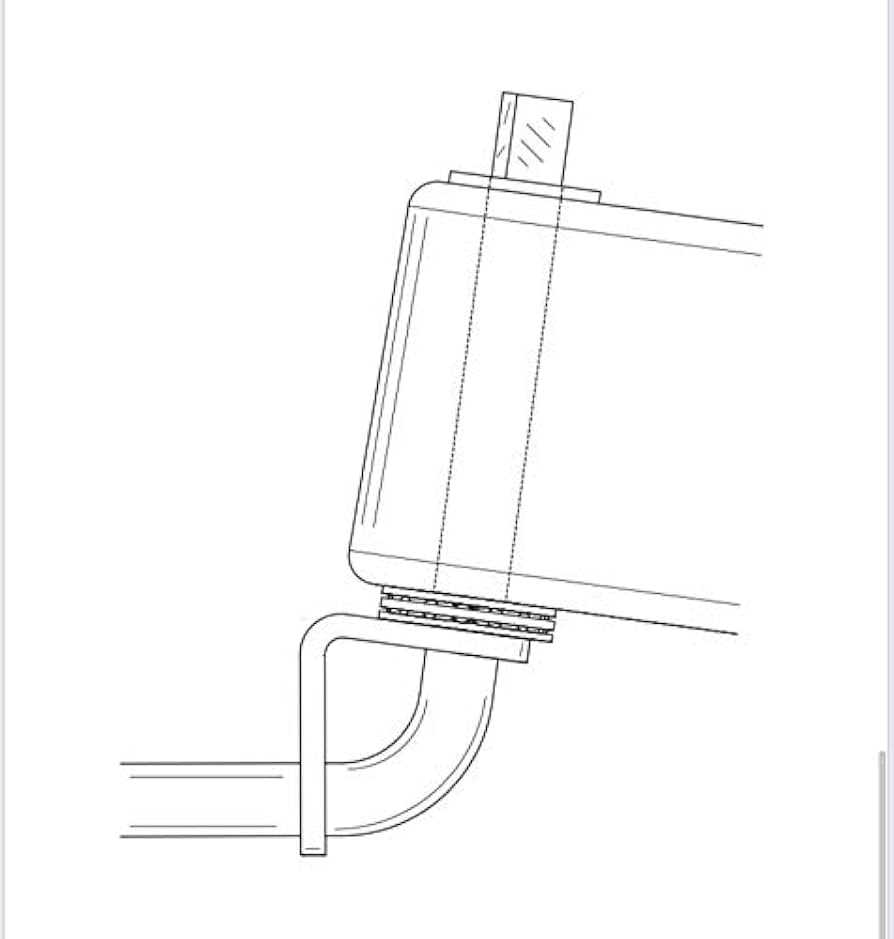
If unusual noises arise during operation, it is often a sign of loose or worn-out parts. Check for friction between moving elements or debris causing a blockage. Lubrication may help resolve minor squeaks, while replacing worn-out components might be necessary for more serious sounds.
Dealing with Inconsistent Movement
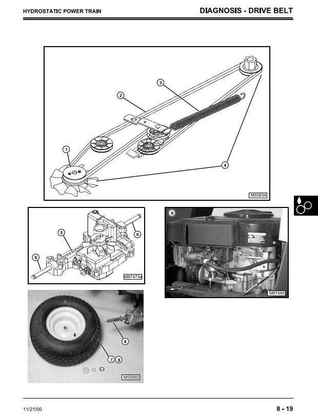
If the system shows irregular motion, verify the condition of the drive mechanism. Slippage or misalignment can often be the cause of inconsistent operation. Make sure belts or gears are tightly fitted and free from wear. Ensuring proper alignment can significantly improve performance and prevent further damage.
|
