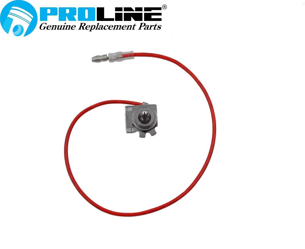
Understanding the internal structure and how different elements connect is crucial for anyone looking to maintain or repair mechanical equipment. Each element, from the smallest detail to the larger assemblies, plays a specific role in ensuring the smooth operation of the machine. Knowing how these elements work together is key to keeping everything running efficiently and prolonging the lifespan of the device.
In this guide, we will explore the layout of important mechanical pieces and how they interrelate. This will provide a clearer picture for those who want to handle repairs or adjustments, making the process more manageable and effective. Attention to detail and familiarity with the layout of these elements can significantly improve the reliability and performance of the equipment.
Understanding the Shindaiwa S25 Machine Layout
The mechanical structure of this device is designed to provide efficient performance across various functions. Its layout features a well-organized assembly of components, allowing for seamless interaction between key elements to ensure smooth operation. Recognizing the placement and purpose of each part is crucial to maintaining and troubleshooting the system effectively.
Main Sections of the Device
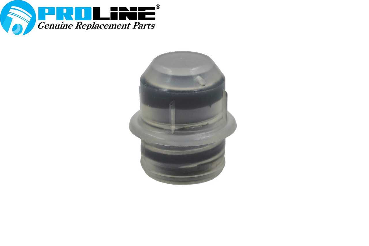
- Engine Unit: The power source that drives the entire mechanism. It houses the combustion chamber, fuel intake, and ignition system, all working in sync to generate the necessary energy.
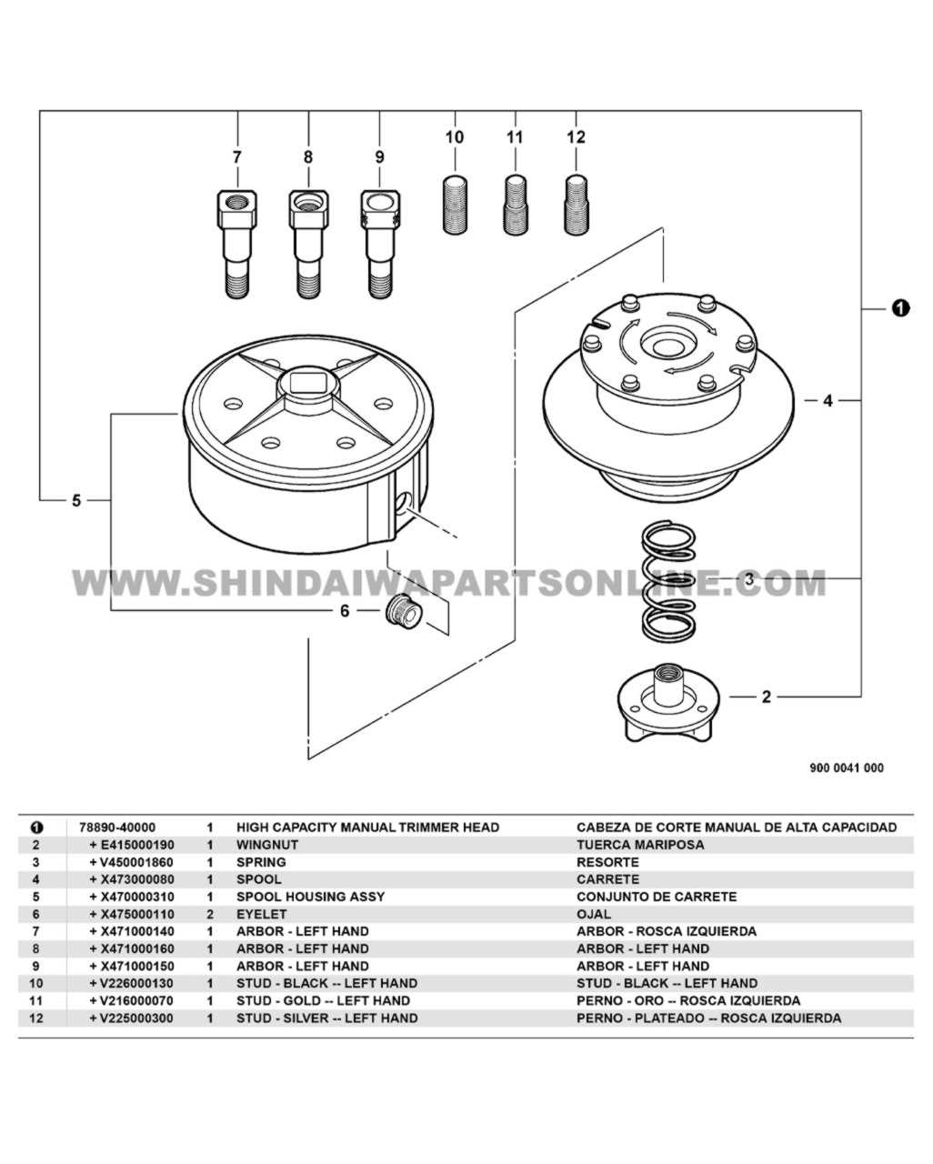
- Cutting Mechanism: A set of sharp tools, designed for precise trimming, is connected to the main power unit
Key Components of the Shindaiwa S25
Understanding the fundamental elements of this tool is crucial for maintaining optimal performance and ensuring longevity. Each individual mechanism works in harmony to deliver efficient results, making it essential to recognize how these various elements contribute to the overall functionality.
Engine and Ignition System

The power source lies at the heart of this machine, responsible for generating the force needed for operation. The ignition system, in turn, ensures that the power unit starts and runs smoothly, converting fuel into mechanical energy with precision. This combination plays a pivotal role in maintaining reliable performance, regardless of the task.
Cutting Mechanism
The cutting mechanism consists of
Fuel System Overview and Maintenance
The fuel system is an essential component that ensures the smooth operation of the engine. Regular maintenance of this system is crucial for optimal performance and longevity. Understanding how it works and what measures are needed to keep it in good condition can prevent unnecessary breakdowns and prolong the lifespan of your equipment.
Key Components of the Fuel System
The fuel system consists of several interconnected elements that ensure a steady flow of fuel to the engine. These include the fuel tank, lines, filters, and carburetor. Each of these parts plays a role in ensuring the correct mixture of fuel and air, allowing for efficient combustion. It’s important
Exploring the Engine Section
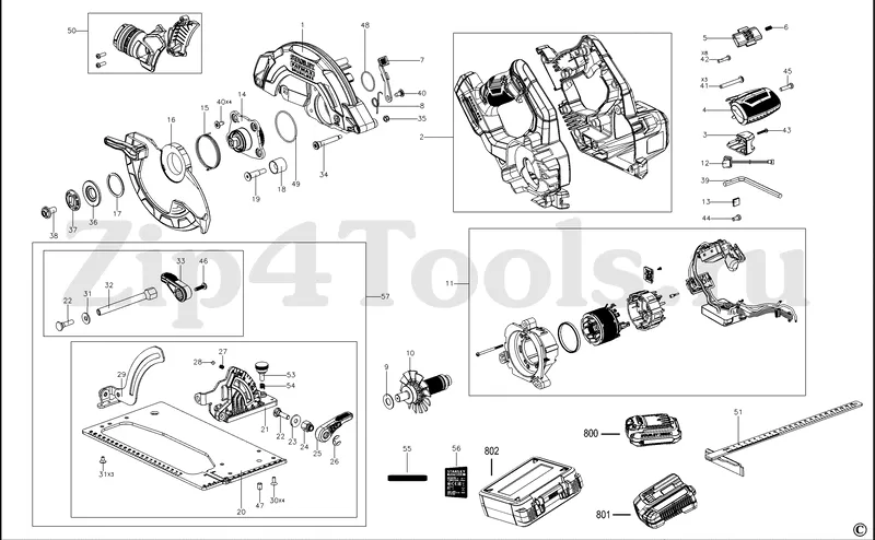
The engine area is the core of the entire mechanical system, where all critical operations converge to generate power and efficiency. This section focuses on the key components and their roles in maintaining optimal functionality. Understanding the layout and relationships between various elements allows for easier maintenance and repair.
Key Components
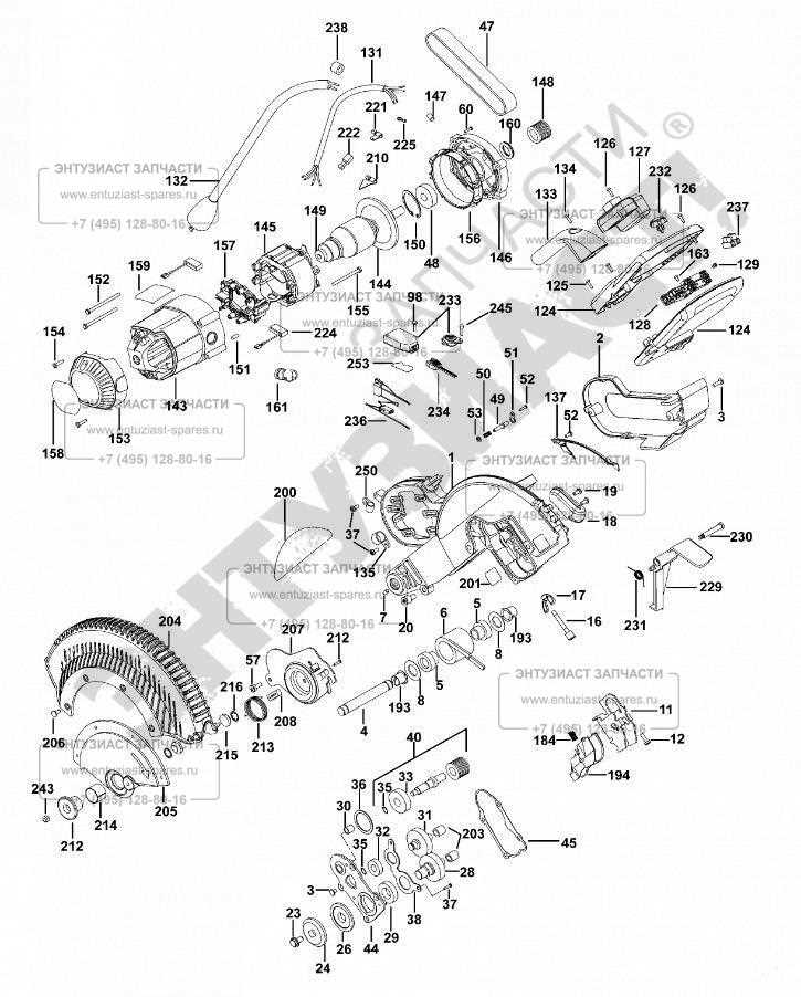
- Cylinder and Piston Assembly: The heart of the system, where fuel is combusted to produce energy.
- Crankshaft: Converts the linear motion of the piston into rotational force, driving the machine.
- Carburetor: Regulates the air-fuel mixture, ensuring the engine runs smoothly under varying conditions.
- Ignition System: Sparks the combustion process, coordinating the energy release at precise moments.
Air Filter and Intake System Structure
The efficiency of any engine relies heavily on its ability to breathe clean air. The intake system is designed to ensure a steady flow of filtered air into the internal components, promoting optimal performance while protecting sensitive parts from contaminants. A well-maintained filtration mechanism is crucial to prevent damage from dust and debris, ensuring a longer lifespan for the machine.
Components of the Intake System
The air filtration and intake system consist of several interdependent components, each playing a vital role in ensuring the engine receives clean air. Below is an overview of the primary elements that contribute to the overall operation:
Component Function Air Filter Traps dust, dirt, and other particles, Guide to the Ignition System
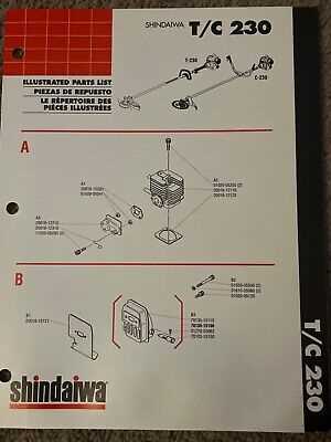
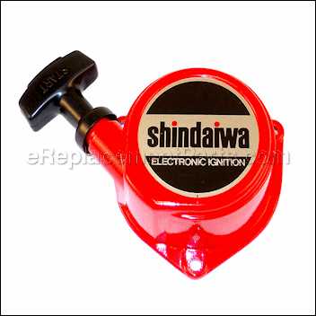
The ignition system is a crucial component in many two-stroke engines, ensuring that the combustion process occurs efficiently and effectively. This system is responsible for generating the spark needed to ignite the fuel-air mixture, allowing the engine to operate smoothly. Understanding the various elements involved can help in troubleshooting and maintaining optimal performance.
Key Components
- Spark Plug: This device ignites the fuel-air mixture, producing the combustion needed for engine power.
- Ignition Coil: It transforms the battery’s low voltage into the high voltage required to create a spark.
- Flywheel Magnet: It generates a magnetic field that powers the ignition coil when the engine is running.
- Ignition Module: This component controls the timing of the spark, ensuring it occurs at the correct moment during the engine cycle.
Maintenance Tips
- Regularly check and replace the spark plug to ensure a strong spark.
- Inspect wiring for any signs of wear or damage that could disrupt the ignition process.
- Test the ignition coil to verify it is functioning correctly.
- Ensure the flywheel magnet is clean and free of debris to maintain proper magnetic function.
Exhaust System Breakdown and Function
The exhaust system plays a crucial role in the overall efficiency and performance of a combustion engine. Its primary function is to guide harmful gases produced during the combustion process away from the engine and into the atmosphere, ensuring optimal engine operation and reducing emissions. Understanding the components of this system is essential for maintaining engine health and maximizing its lifespan.
Key Components of the Exhaust Assembly
The exhaust assembly consists of several integral parts, including the manifold, catalytic converter, muffler, and exhaust pipes. The manifold collects exhaust gases from the engine’s cylinders and directs them into the subsequent components. The catalytic converter serves to convert harmful emissions into less toxic substances before they exit the system. The muffler plays a vital role in minimizing noise produced by the engine, while the exhaust pipes facilitate the flow of gases from the engine to the atmosphere.
Functionality and Maintenance
Regular maintenance of the exhaust system is essential to ensure its effective operation. Inspecting for leaks, rust, and blockages can prevent performance issues and prolong the lifespan of the engine. A well-functioning exhaust system not only enhances engine efficiency but also contributes to a cleaner environment by reducing harmful emissions.
Clutch and Transmission Mechanism
The functionality of a cutting tool is heavily reliant on its coupling and drive system. These components work in tandem to ensure smooth operation and optimal performance. Understanding the intricacies of this assembly is crucial for maintenance and efficient use.
Components Overview
- Clutch: The device that engages and disengages the power from the engine to the output shaft.
- Drive Shaft: Transfers rotational force from the engine to the cutting head.
- Gears: Alter the speed and torque output, allowing for versatility in different tasks.
Functionality and Maintenance
- Regular inspection of the clutch system is essential to prevent slippage and ensure effective engagement.
- Lubrication of moving parts reduces wear and enhances performance.
- Replacing worn components promptly can avoid extensive damage and costly repairs.
In conclusion, proper care of the coupling and transmission assembly not only extends the lifespan of the tool but also improves overall efficiency during operation.
Handle and Control Assembly Configuration
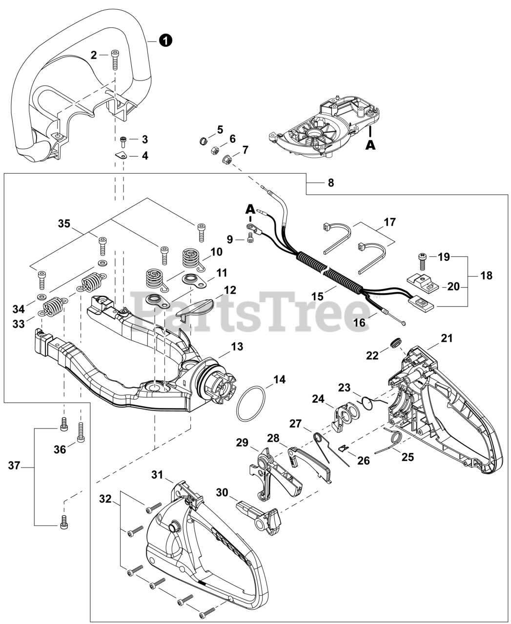
The configuration of the handle and control assembly plays a vital role in the overall functionality and user experience of outdoor power equipment. This section provides insights into the various components that contribute to the operation and ergonomics of these devices.
Understanding the layout and design of the control elements is essential for effective use and maintenance. The following components are typically included in this assembly:
- Grip Handle: Provides comfort and stability during operation.
- Throttle Control: Regulates engine speed, allowing for precise adjustments based on task requirements.
- Switch Assembly: Enables quick activation and deactivation of the equipment, ensuring user safety.
- Control Levers: Facilitate easy maneuvering and handling, enhancing control over the equipment.
- Mounting Brackets: Securely attach the assembly to the main body, ensuring durability and reliability.
Maintaining the integrity of the handle and control assembly is crucial for optimal performance. Regular inspections and proper adjustments can enhance the longevity and effectiveness of the equipment.
Maintenance Tips for Key Parts
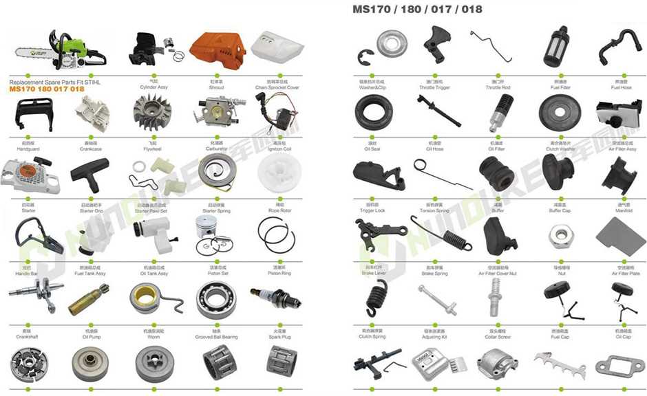
Proper upkeep of essential components is crucial for ensuring optimal performance and longevity of your equipment. Regular attention to these parts can prevent wear and tear, reduce the likelihood of malfunctions, and enhance overall efficiency. Below are some effective maintenance strategies to keep your machine running smoothly.
Regular Cleaning
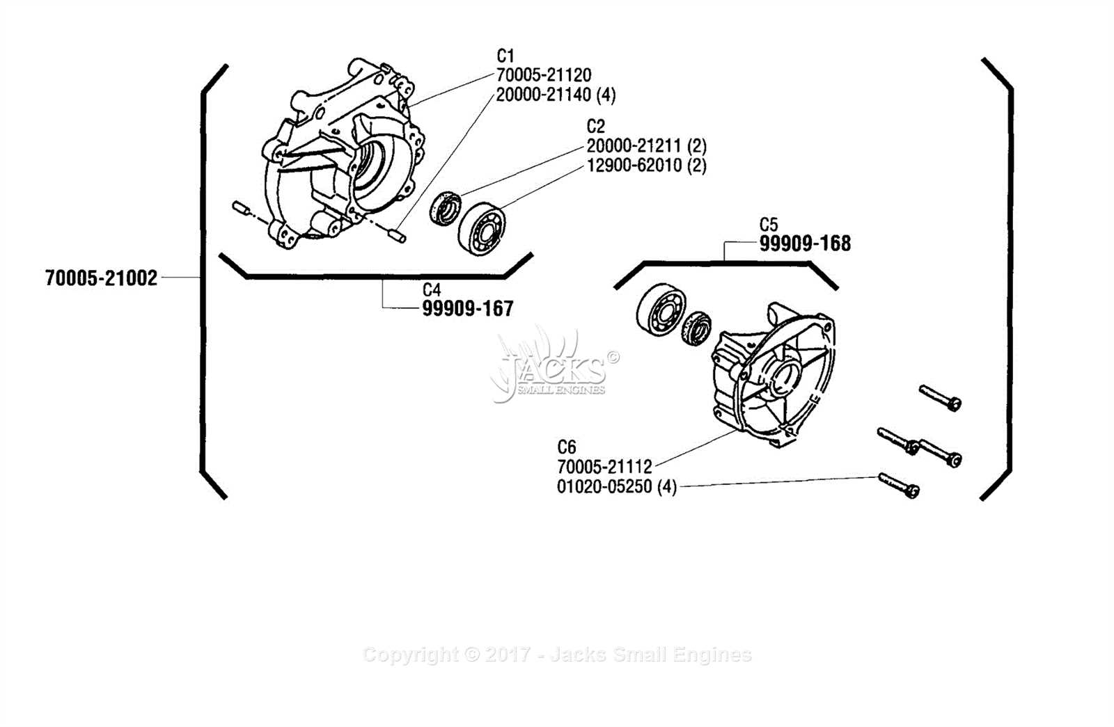
Cleaning is vital in maintaining the functionality of critical elements. Dust, debris, and residue can accumulate over time, leading to overheating or reduced efficiency. Ensure you regularly wipe down surfaces and clear away any buildup to keep everything in top condition.
Periodic Inspections
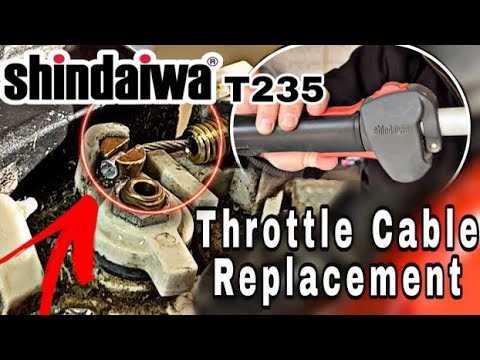
Conducting routine checks on various components can help identify potential issues before they escalate. Look for signs of wear, damage, or misalignment, and address these problems promptly. This proactive approach can save time and resources in the long run.
Replacement Guide for Worn Components
Maintaining the efficiency and performance of your equipment often requires replacing worn or damaged elements. Identifying components that need attention can help prolong the lifespan of your machine and ensure its optimal functioning. This guide aims to provide essential insights into the identification and replacement of these crucial parts.
When assessing which elements to replace, it’s vital to conduct a thorough inspection. Look for signs of wear such as cracks, rust, or excessive friction. Ensuring you have the correct replacements is essential for maintaining performance standards.
Component Signs of Wear Replacement Part Number Blade Chipping or dullness 123456 Filter Clogged or discolored 234567 Fuel Line Cracks or leaks 345678 Starter Cord Torn or frayed 456789 Once you have identified the components that need replacement, acquiring the right parts is crucial. Always refer to your equipment’s specifications to ensure compatibility. Proper installation of new elements will not only enhance the machine’s functionality but also improve overall safety during operation.