When it comes to versatile and effective tools for everyday tasks, finding the right equipment is crucial. A device that offers both durability and precision can make a significant difference in achieving desired results. This section introduces an efficient tool known for its robustness and reliability in handling various projects. It is designed to meet the needs of both professionals and hobbyists alike, providing smooth operation and consistent performance.
Understanding the internal structure and components of such a tool can greatly aid in troubleshooting and maintaining its functionality. This breakdown offers insights into the mechanism and essential elements that work together, ensuring optimal performance and longevity. Whether you are looking to perform routine maintenance or simply curious about its construction, the following information will guide you through key aspects of this remarkable tool.
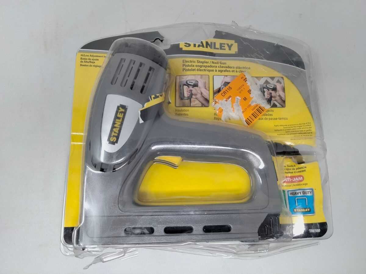
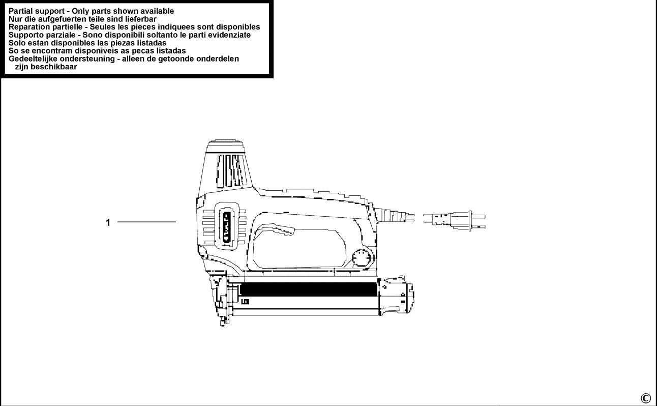
Overview of Stanley TRE550 Components
The tool consists of various elements that work together to deliver efficient fastening capabilities. Each piece plays a crucial role in the functionality, ensuring seamless operation during use. Understanding these elements helps users maintain and repair the equipment effectively.
Main Operational Elements

Key operational features include mechanisms responsible for driving staples and nails with precision. These are supported by internal structures that provide the necessary force and accuracy, making it a reliable option for different fastening tasks.
Supporting Structures
The supporting components serve as the framework, ensuring the stability and durability of the device. They are built to withstand regular use and contribute to its overall longevity by protecting more delicate parts from wear and tear.
Trigger Mechanism and Function
The trigger system plays a crucial role in the operation of any electric tool, ensuring efficient activation and control over the firing sequence. This component initiates the internal mechanisms, leading to the proper functioning of the device, allowing precise control with minimal effort from the user.
| Component | Description |
|---|---|
| Trigger Switch | Responsible for starting the firing process when pressed, activating the internal components. |
| Safety Mechanism | Prevents unintentional activation, ensuring safe use under various conditions. |
| Internal Linkage | Transfers the motion from the trigger to other operational parts, enabling efficient performance. |
The interaction between these elements allows for smooth, consistent operation, providing the necessary force to complete tasks while maintaining safety and accuracy.
Internal Electrical Connections Layout
The internal wiring configuration plays a crucial role in the overall performance and functionality of the device. Understanding the layout of these connections helps to identify how electrical components work together, ensuring efficient operation and safety. By examining the arrangement, one can gain insights into the flow of electricity through various circuits, switches, and connectors.
Key Elements of the Layout
The internal electrical connections typically involve multiple elements such as wiring routes, connectors, and terminals. Each of these components is meticulously arranged to establish clear pathways for power distribution. Proper alignment of these elements is essential to avoid interference and ensure smooth electrical transitions.
Connector and Terminal Placement
The connectors and terminals are strategically positioned to link various sections of the device, enabling the smooth transfer of power. Their placement is critical in maintaining an uninterrupted flow of current, reducing the risk of short circuits and other electrical issues. Regular inspection of these areas can prevent potential malfunctions.
Staple Magazine Structure and Design
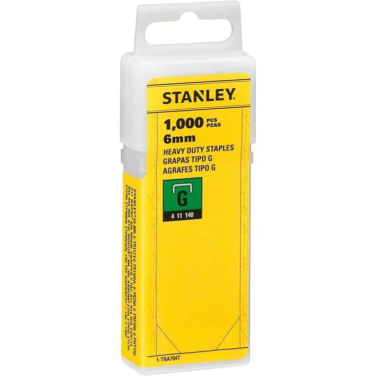
The design of a staple magazine is integral to ensuring smooth and efficient operation of the tool. It houses the fasteners and aligns them properly, making it easier to load and dispense staples consistently. A well-constructed magazine improves the overall durability and performance of the device, preventing jams and ensuring a continuous workflow.
Material and Build: The magazine is typically made from sturdy materials to withstand repeated use. Its internal mechanism guides the staples along a predefined path, ensuring each one is ready for the next use.
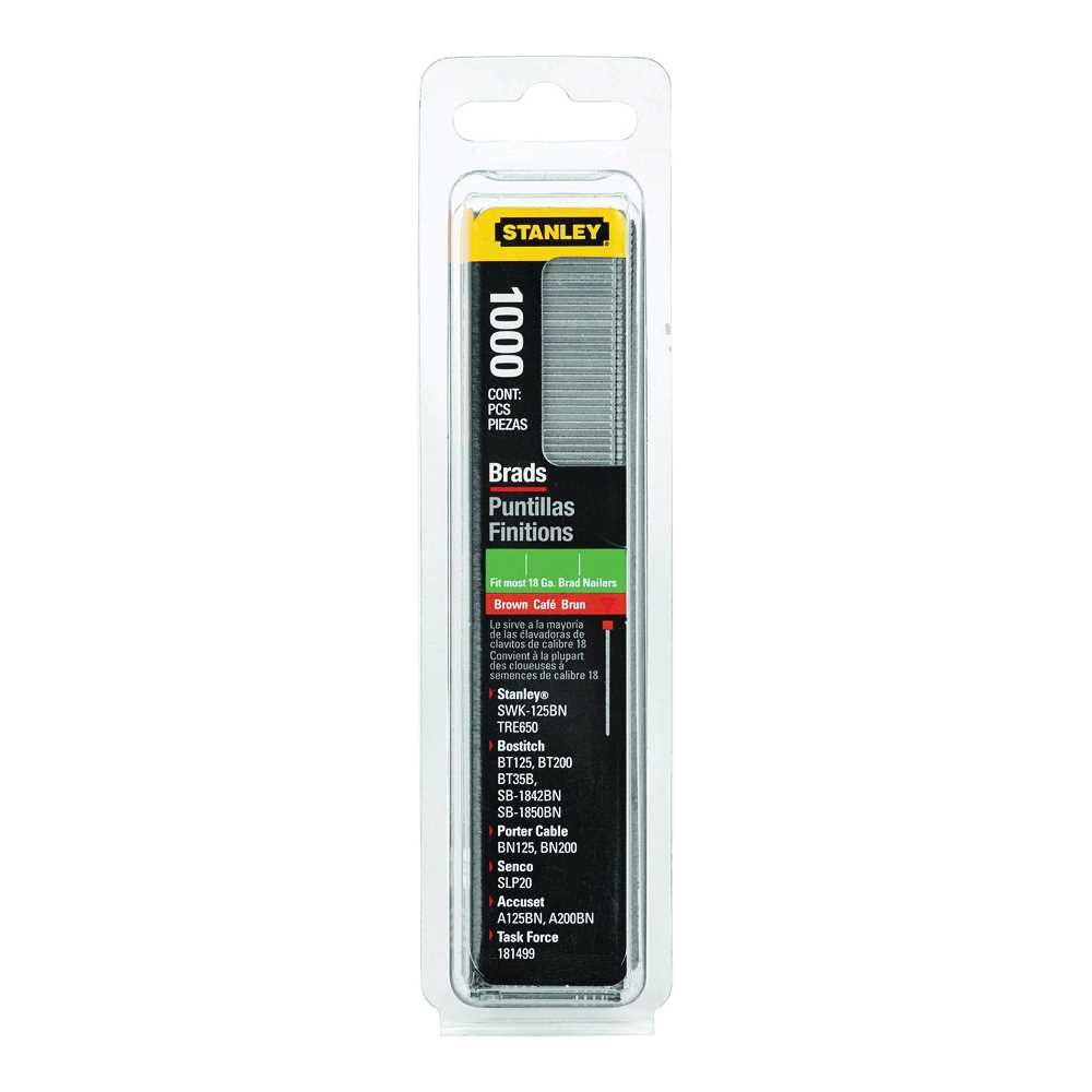
Compatibility and Size: Different magazines may be designed for various sizes of staples, which makes the structure versatile. Ensuring that the magazine fits the proper staples is key to maintaining functionality and avoiding misfires.
Power Cord Assembly and Maintenance
The power cord plays a crucial role in the overall operation of the tool, ensuring a steady and reliable connection to the power source. Regular maintenance and proper assembly of the cord are essential for maintaining performance and safety during use. In this section, we’ll explore the key steps to ensure the cord is securely connected and functioning correctly, along with tips to prevent wear and tear.
Assembly: Proper alignment of the cord with the tool is important to avoid accidental disconnections during operation. Make sure the cord is fully inserted and locked into place, checking that no exposed wires are visible. Ensuring a snug connection is vital for uninterrupted functionality.
Maintenance: Inspect the cord regularly for signs of damage such as fraying or cracks in the insulation. If any damage is found, replace the cord immediately to avoid electrical hazards. Additionally, avoid kinking or tightly wrapping the cord, as this can lead to premature wear.
Tip: Always unplug the tool before inspecting or performing any maintenance on the power cord. This simple precaution helps prevent accidental injuries or damage to the tool.
Housing and Exterior Shell Details
The housing and outer shell of a device play a crucial role in its overall functionality and durability. These components not only provide protection for the internal mechanisms but also influence the device’s ergonomics and aesthetics. Understanding the features and design elements of the exterior is essential for effective maintenance and operation.
Material Composition
The outer casing is typically crafted from robust materials that resist wear and tear. Common choices include high-grade plastics and metals, which offer both lightweight characteristics and strength. These materials are selected to ensure longevity while safeguarding the internal components from environmental factors.
Structural Features
Key structural elements of the exterior shell include grips, mounting points, and ventilation slots. Ergonomic designs enhance user comfort, making the device easier to handle during operation. Additionally, well-placed ventilation openings are vital for maintaining optimal temperatures, preventing overheating during prolonged use.
Spring and Piston Assembly Diagram
This section explores the components involved in the assembly of the spring and piston mechanism. Understanding the arrangement and interaction of these elements is crucial for the efficient functioning of the device. Proper maintenance and assembly can significantly enhance performance and longevity.
Components Overview

The assembly consists of several key parts that work together to create the necessary pressure and motion. Each component plays a vital role in ensuring smooth operation.
| Component | Description |
|---|---|
| Spring | Provides the necessary force for the piston to operate efficiently. |
| Piston | Converts the spring’s force into mechanical motion, enabling the system to perform its intended function. |
| Cylinder | Houses the piston, allowing it to move freely while containing the compressed spring. |
| Retaining Ring | Secures the piston within the cylinder, preventing it from dislodging during operation. |
Assembly Process
To assemble the spring and piston effectively, ensure each part is aligned correctly and securely fitted. This process is essential for achieving optimal performance and preventing mechanical failures.
Safety Mechanism and Its Role
The implementation of safety mechanisms in power tools is crucial for ensuring user protection and preventing accidents during operation. These features are designed to minimize the risk of injury by automatically controlling the tool’s functionality in various scenarios. A robust safety system not only enhances the overall reliability of the device but also boosts user confidence while working.
Functionality and Importance
Safety features typically include automatic shut-off capabilities and lock mechanisms that prevent unintentional activation. Such systems play an essential role in safeguarding users from potential hazards, especially in high-risk environments. By integrating these protective elements, manufacturers can significantly reduce the likelihood of accidents, ensuring a safer working experience.
Maintenance and Best Practices
Regular maintenance of the safety components is vital to ensure their proper functionality. Users should inspect these mechanisms frequently and follow best practices for tool usage to maintain their effectiveness. Understanding how these systems operate and recognizing their importance can lead to safer and more efficient operations.
Stapler Base Plate Components
The base plate of a stapling device plays a crucial role in ensuring stability and functionality during operation. It serves as the foundational element that supports various mechanisms, allowing for smooth and efficient stapling tasks. Understanding the individual elements that make up this component is essential for proper maintenance and effective use.
At the heart of the base plate are several integral pieces that contribute to its overall performance. The primary structural element provides rigidity and support, ensuring that the device remains stable when engaged. Additionally, several guide rails are often incorporated to facilitate accurate alignment of the materials being stapled.
Another important feature includes the fastening mechanisms, which secure the base plate to the main body of the device. These fasteners must be robust to withstand repeated use while ensuring easy accessibility for maintenance. Furthermore, various cushioning elements may be present to absorb impact and enhance user comfort during operation.
Lastly, the surface texture of the base plate can affect the device’s performance, with non-slip materials providing added stability during use. Familiarity with these components allows users to troubleshoot issues effectively and perform necessary repairs, ultimately extending the lifespan of the stapling tool.
Guide Rail and Track Alignment
Ensuring proper alignment of the guide rails and tracks is essential for the efficient operation of any system relying on these components. Accurate alignment not only enhances the overall performance but also prolongs the lifespan of the equipment, reducing the likelihood of malfunctions.
Importance of Alignment
Misalignment can lead to various issues, including increased wear on moving parts, operational inefficiencies, and even safety hazards. Regular checks and adjustments are necessary to maintain optimal conditions, ensuring that the tracks are straight and level.
Steps for Effective Alignment
To achieve precise alignment, start by visually inspecting the entire length of the guide rails and tracks for any obvious deviations. Utilize measuring tools to confirm that the components are parallel and at the correct height. Make necessary adjustments, securing all fasteners tightly to maintain stability. Periodic re-evaluation is also advisable to catch any shifts that may occur during operation.
Wiring and Circuit Board Overview
This section delves into the intricacies of the electrical connections and the printed circuit assembly that underpin device functionality. Understanding the layout and interconnections is essential for troubleshooting and optimizing performance.
The electrical system consists of various components working in tandem to ensure efficient operation. Below are the key elements involved:
- Wiring Harness: A collection of wires bundled together that facilitates the transmission of electrical signals.
- Power Supply: The source of energy that powers the entire system, typically converting AC to DC.
- Control Board: The main circuit board that houses various electronic components, including resistors, capacitors, and microcontrollers.
Moreover, the connection points play a critical role in ensuring the stability of the system:
- Input Terminals: Points where power and data are introduced into the assembly.
- Output Connections: Locations where the processed signals exit the system to activate external devices.
- Ground Connections: Essential for safety and preventing electrical interference.
In conclusion, a comprehensive grasp of the wiring configuration and circuit board layout is vital for effective maintenance and repair tasks.
Drive Pin Mechanism Breakdown
The drive pin mechanism plays a crucial role in the functionality of various tools and equipment. It serves as a key component that facilitates the transfer of rotational motion from the motor to the working parts, ensuring effective operation. Understanding its structure and function can significantly enhance the overall performance and reliability of the device.
This mechanism typically consists of several interconnected elements that work together seamlessly. The primary component, the drive pin itself, engages with other parts to convert energy into motion. Additionally, the arrangement of gears and levers supports the drive pin’s movement, allowing for precise control over the tool’s operation.
Proper maintenance and inspection of the drive pin mechanism are essential for optimal performance. Regular checks can prevent wear and tear, which may lead to operational failures. Identifying potential issues early can save time and resources, ensuring the equipment remains in peak condition.
In summary, a thorough understanding of the drive pin mechanism is vital for anyone looking to optimize their equipment’s performance. By familiarizing oneself with its components and functions, users can enhance the longevity and efficiency of their tools.
Replacing Worn Out Internal Parts

When internal components begin to show signs of wear, it is crucial to address the issue promptly to maintain optimal performance and prolong the lifespan of the equipment. Regular maintenance and timely replacements can prevent further damage and ensure reliable operation. Understanding the signs of deterioration and the steps involved in replacing these components is essential for effective upkeep.
Identifying Worn Components
Before proceeding with replacements, it is important to identify which components have deteriorated. Common signs include unusual noises, decreased efficiency, and visible wear. Inspecting these elements can help pinpoint the specific parts that require attention. Regular checks can also help in detecting issues early, making repairs more manageable and less costly.
Steps for Replacement
Once worn components are identified, follow these steps for successful replacement:
| Step | Description |
|---|---|
| 1 | Disconnect the device from power to ensure safety during repairs. |
| 2 | Carefully remove the outer casing to access internal components. |
| 3 | Remove the identified worn components, taking care to note their placement. |
| 4 | Install the new components, ensuring they are securely fitted. |
| 5 | Reassemble the outer casing and reconnect the power supply. |