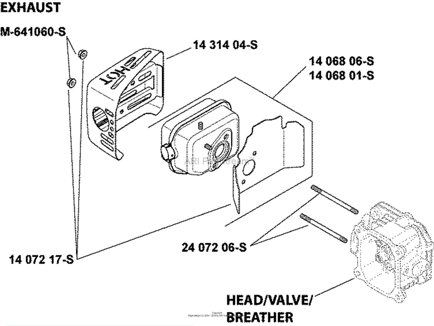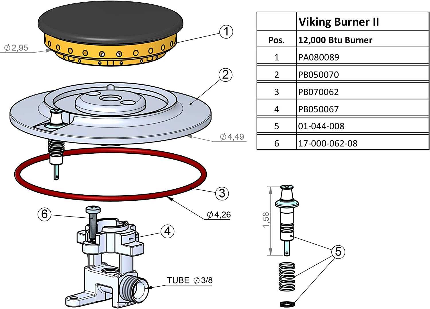
Understanding the intricate layout of mechanical systems can be essential when it comes to maintenance or upgrades. Whether you’re a professional technician or a hobbyist, having a detailed representation of how components are arranged allows for more efficient repairs and adjustments.
By studying the overall structure, it’s possible to identify how different elements interact, helping prevent potential issues and ensuring the system operates at peak performance. This guide will offer insights into the composition and configuration of various assemblies, providing clarity for those looking to deepen their knowledge.
Detailed illustrations and schematics make it easier to navigate complex systems, offering a roadmap for disassembly or reassembly. Knowing the exact placement of each element ensures accuracy and efficiency in tasks involving the setup.
Understanding Viking Appliance Components
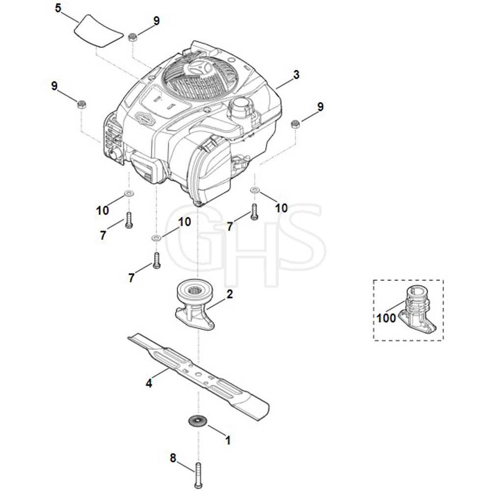
To fully comprehend the structure and function of home appliances, it is essential to understand the various elements that make up these devices. These components work together to ensure efficient operation, providing the desired results in cooking, cleaning, and other household tasks.
Key Functional Elements
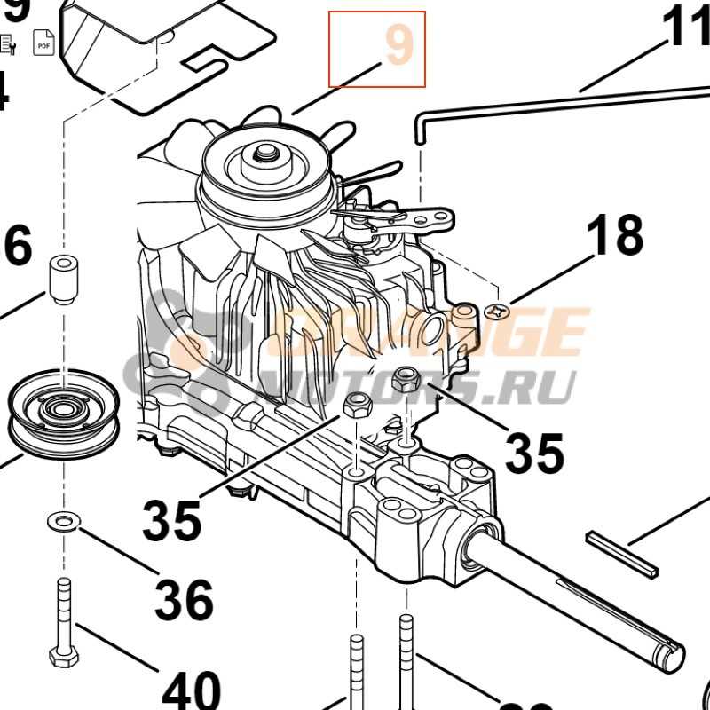
Appliance mechanisms typically consist of systems that control temperature, power flow, and operation timing. Understanding these systems can help with identifying potential issues and maintaining the appliance’s performance over time.
Importance of Proper Maintenance
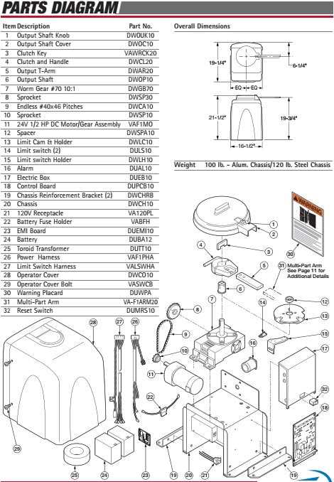
Regular inspection and care of these elements are crucial for the
Exploring Key Parts of Viking Equipment
Understanding the essential components of specialized machinery can greatly enhance both its maintenance and performance. Identifying the individual elements that make up complex systems allows users to troubleshoot effectively and ensure longevity. These components are intricately designed to work together, making it crucial to know their specific roles and functions.
Critical components within these systems include structural elements, control mechanisms, and operational tools. Each of these plays a vital part in ensuring the equipment functions efficiently, contributing to the overall performance of the system. Recognizing how these elements interact can prevent malfunctions and enhance productivity.
Diagram Insights for Viking Systems
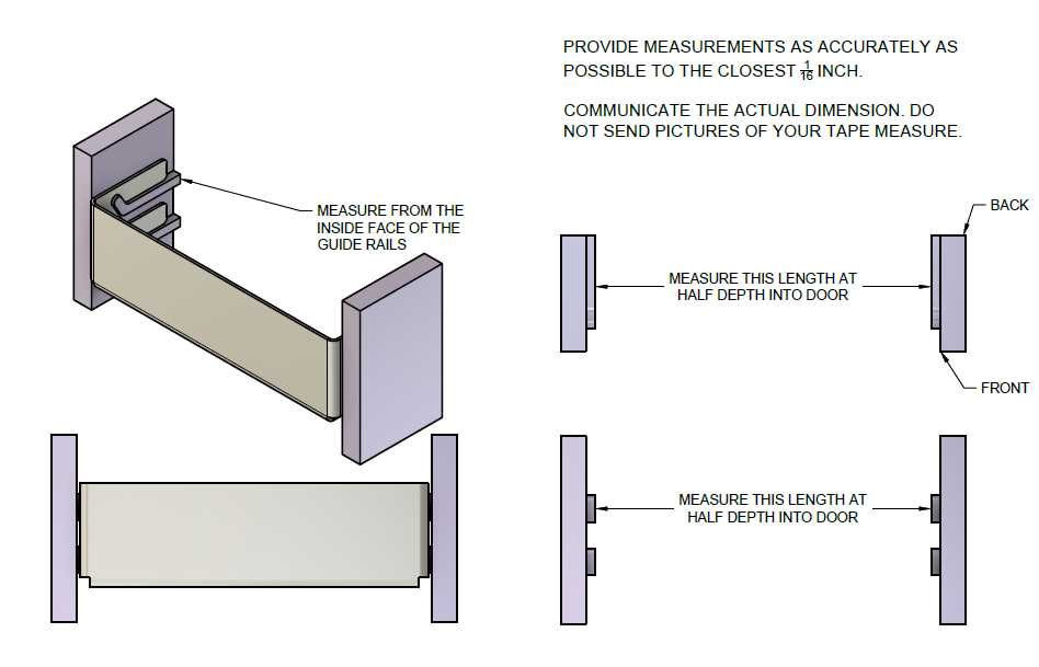
Understanding the structure and configuration of intricate setups can be vital for ensuring efficient functionality. These visual representations provide clarity, aiding in the recognition of various connections and components within complex frameworks. By decoding these illustrations, users can navigate through intricate networks with confidence.
Interpreting Visual Schematics
Visual schematics serve as a roadmap, offering a clear guide to the arrangement of different elements. They simplify the process of identifying key components, ensuring accuracy during assembly or repair. Grasping the basic logic of these layouts helps to streamline operations and avoid common errors.
Ensuring Correct Connections
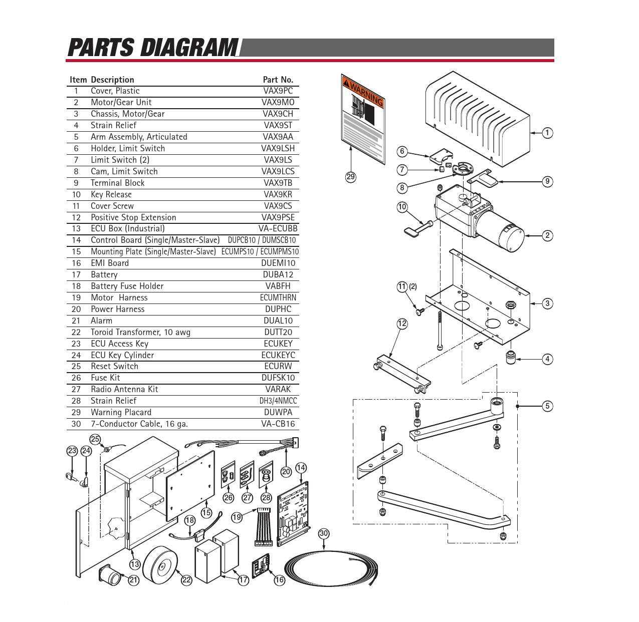
Proper connections are essential for optimal performance. A detailed examination of these representations can reveal
Identifying Essential Viking Replacement Parts
Recognizing the key components necessary for system maintenance and repair is critical for ensuring longevity and functionality. Understanding how to differentiate among these core elements can simplify the repair process and help avoid unnecessary complications.
| Component | Function | Maintenance Tips | |||||||||||||||||
|---|---|---|---|---|---|---|---|---|---|---|---|---|---|---|---|---|---|---|---|
| Burner Assembly | Generates heat for cooking | Regular cleaning to prevent blockages | |||||||||||||||||
| Ignition System | Starts the heating process | Check connections for loose wires | |||||||||||||||||
| Component | Function |
|---|---|
| Framework | Provides structural support |
| Fasteners | Secures components together |
| Shielding | Protects internal mechanisms |
| Control Elements | Manages operational tasks |
Assembly Process Tips
To ensure a smooth assembly experience, consider the following tips:
- Start with the foundation to ensure stability.
- Double-check connections to avoid future issues.
- Consult reference materials for specific guidance on assembly techniques.
Component Functions in Viking Devices

The functionality of various elements in specialized equipment is crucial for ensuring optimal performance and reliability. Each component plays a distinct role, contributing to the overall efficiency and capability of the system. Understanding these roles helps users appreciate how different parts interact and support the device’s intended operations.
Key Element Roles
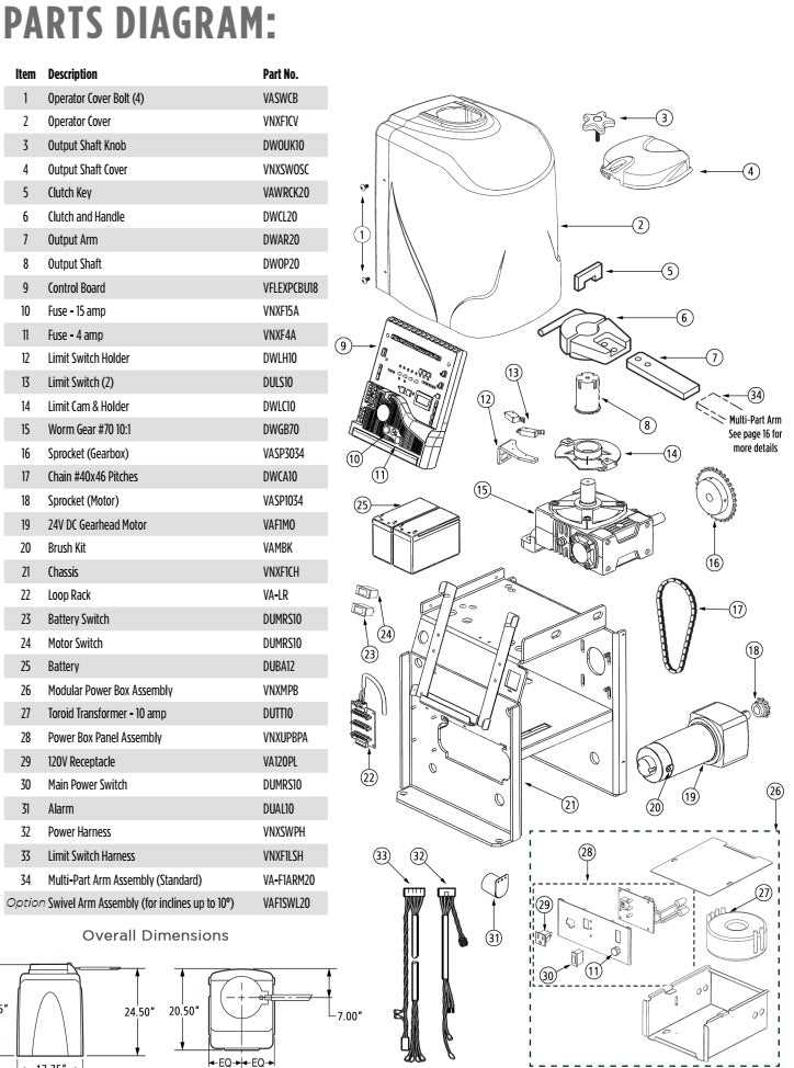
Among the primary components, the power source serves as the foundation for operation, supplying the necessary energy for all activities. Control units facilitate the management of processes, ensuring precise execution of commands. Communication interfaces enable connectivity, allowing for data exchange between devices and facilitating user interaction.
Importance of Component Integrity
Maintaining the integrity of each component is vital. Regular maintenance ensures that all elements function optimally, preventing disruptions in operation. Awareness of each component’s role empowers users to identify potential issues and take corrective measures, enhancing the longevity and reliability of the equipment.
Comprehensive View of Viking Diagrams
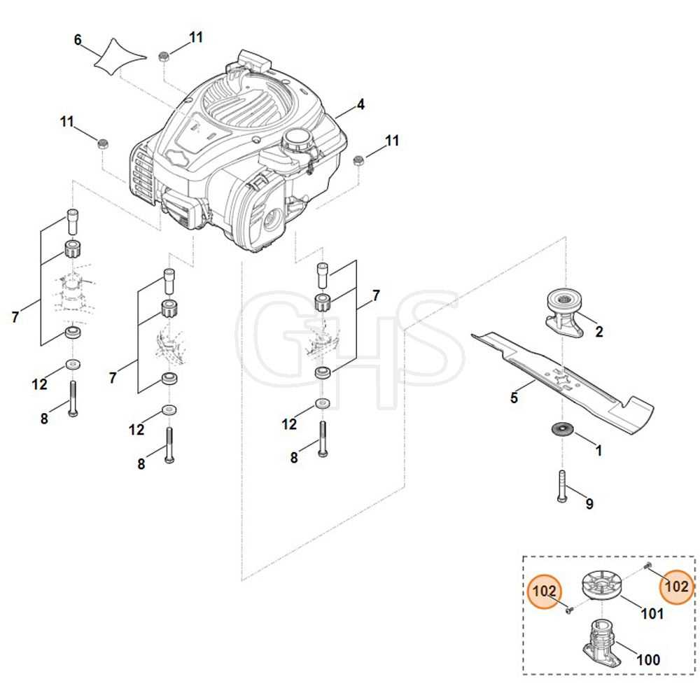
This section aims to provide an extensive overview of the schematics associated with the subject. Understanding these visual representations is essential for grasping the complexities involved, as they serve as vital tools for interpretation and analysis. By exploring the intricacies of these illustrations, readers can gain insights into their functionality and relevance.
The following table outlines key features and aspects commonly found in these illustrations:
| Feature | Description |
|---|---|
| Structure | Illustrates the configuration and arrangement of components. |
| Connections | Highlights the interrelationships and linkages between elements. |
| Functionality | Explains the operational roles of various parts within the system. |
| Labels | Provides identifiers for each component to enhance clarity. |
Maintenance Tips for Viking Parts
Proper upkeep is essential for ensuring the longevity and efficiency of equipment components. Regular maintenance helps identify potential issues before they escalate, enhancing performance and reliability. Here are some useful guidelines for maintaining various components of your machinery.
- Regular Inspections: Check for any signs of wear, damage, or misalignment. Early detection can prevent costly repairs.
- Cleaning: Keep all components free from dirt and debris. Use appropriate cleaning agents to avoid damaging sensitive parts.
- Lubrication: Ensure that moving parts are adequately lubricated to reduce friction and wear. Follow manufacturer recommendations for lubricant types and intervals.
- Calibration: Periodically calibrate settings to ensure optimal performance. This includes checking for accuracy and adjusting as necessary.
- Replacement Schedule: Maintain a schedule for replacing worn or outdated components. This practice can enhance efficiency and safety.
By following these maintenance tips, you can ensure that your equipment remains in excellent condition, ultimately extending its lifespan and improving functionality.
How to Interpret Viking Parts Layout
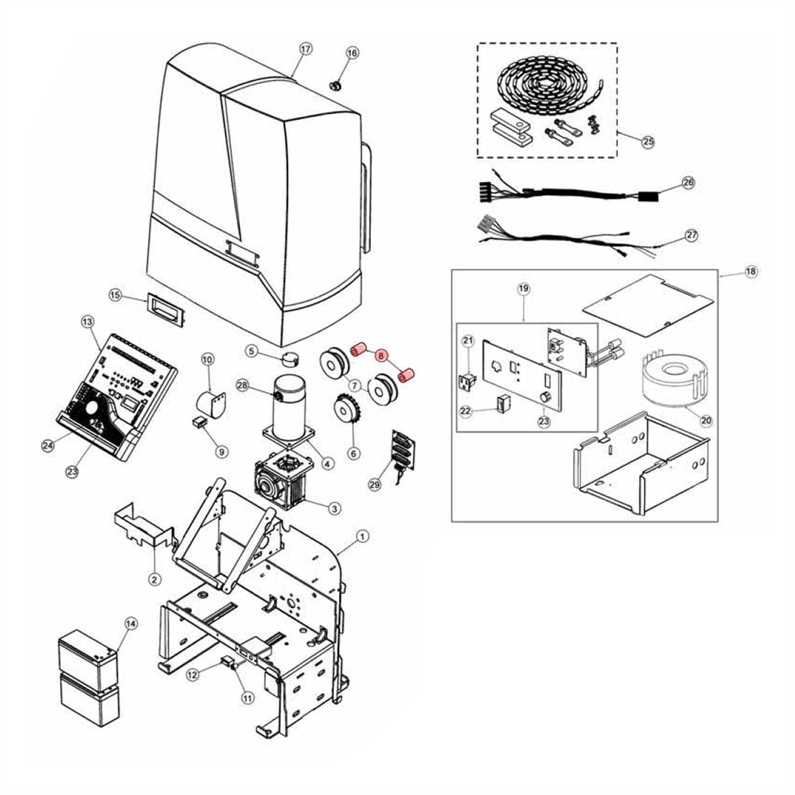
Understanding the configuration of components within a specific system is essential for effective assembly, maintenance, and troubleshooting. This knowledge enables users to navigate through the various elements and their interconnections, facilitating a more efficient workflow and enhancing overall performance.
Identifying Key Components
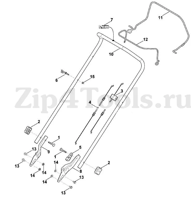
Begin by familiarizing yourself with the major elements represented in the configuration. Look for labels or symbols that indicate the function of each part. Recognizing these components will help you grasp their roles within the broader framework, allowing for easier identification during practical application.
Understanding Connections and Relationships
Next, focus on the connections between different elements. Pay attention to how components are linked and the nature of their interactions. Understanding these relationships is crucial for troubleshooting and optimizing functionality, as it allows you to see how adjustments in one area may affect others.
Common Issues with Viking Component Diagrams
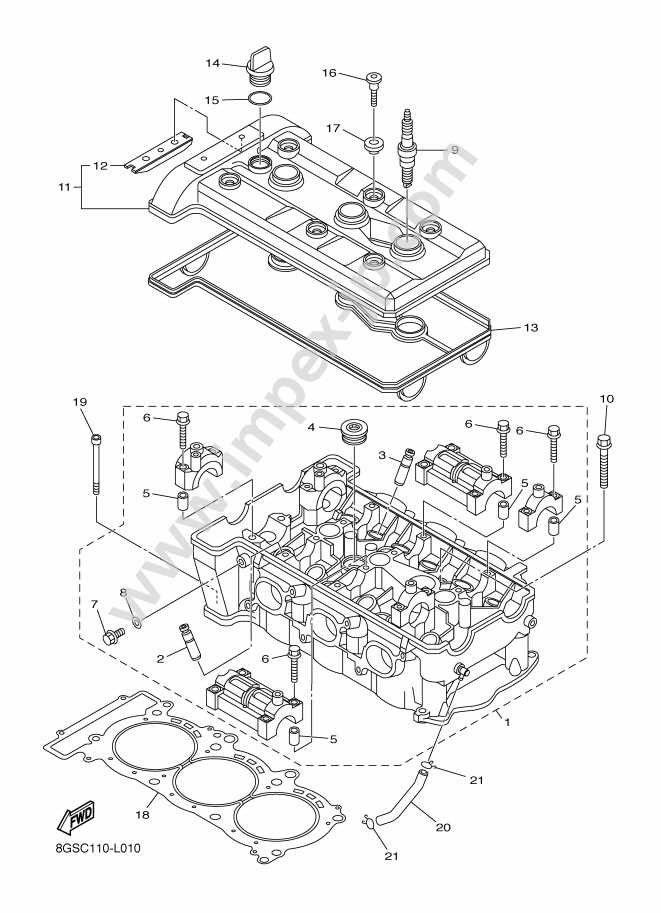
When working with schematic representations of mechanical assemblies, several challenges can arise. These difficulties may hinder effective communication and understanding among team members. Recognizing and addressing these issues is essential for improving the overall workflow and ensuring that the design meets its intended purpose.
Ambiguities in Representation
One common issue is the ambiguity in how components are represented. Misinterpretations can occur due to:
- Inconsistent symbols for similar elements.
- Vague annotations that lack clarity.
- Poor alignment between components that leads to confusion.
Difficulty in Updating Information
Another significant challenge is the difficulty in maintaining and updating information within these schematics. This can result in:
- Outdated data that misleads users.
- Increased time spent on revisions and corrections.
- Frustration among team members due to unclear instructions.
