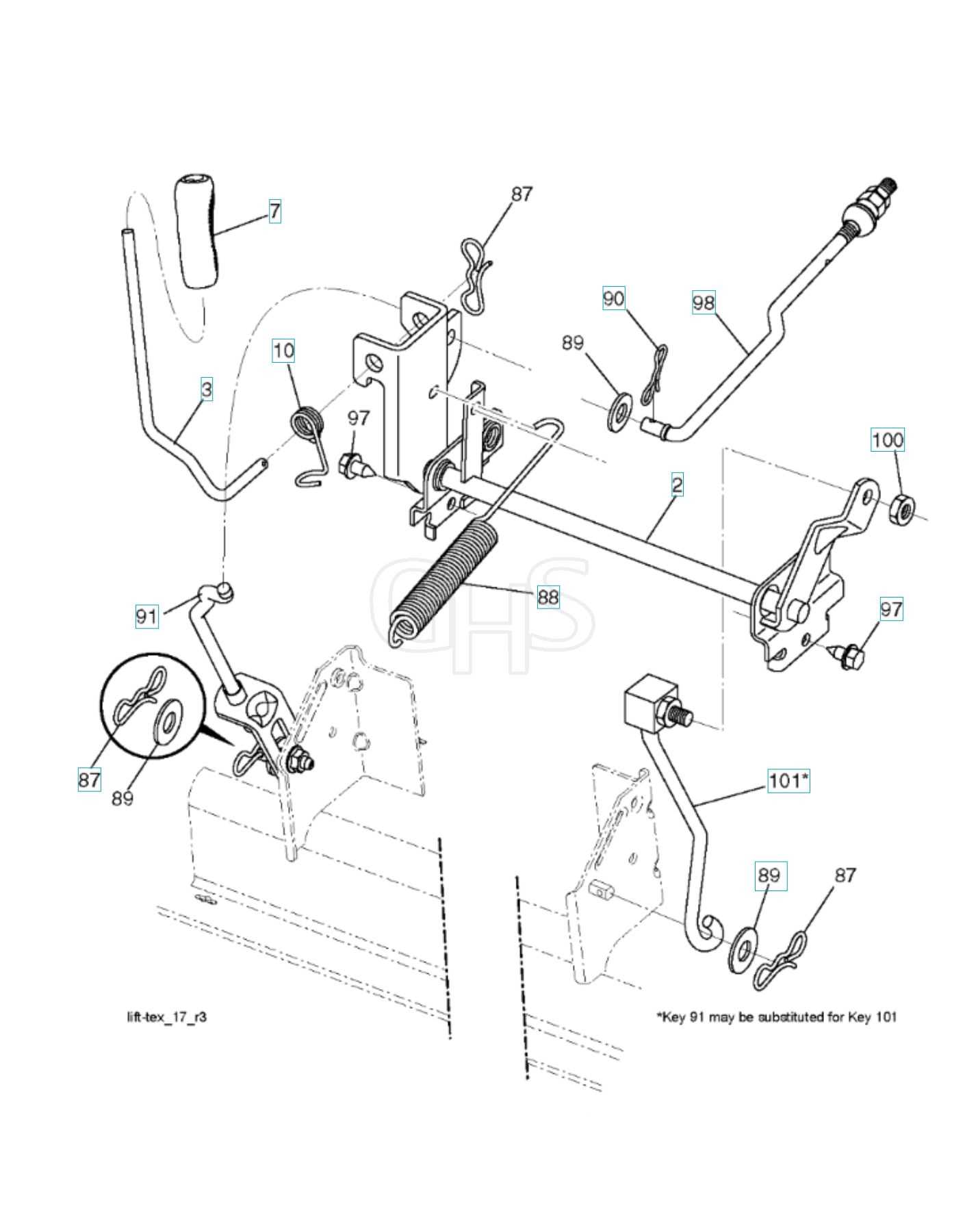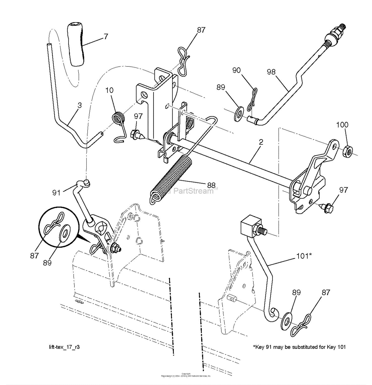
A detailed breakdown of intricate assemblies is crucial for understanding how various elements interact to ensure smooth operation. This section offers insights into the arrangement of crucial mechanical and structural elements that contribute to optimal performance. Whether you’re maintaining, repairing, or simply exploring, it’s essential to grasp the underlying structure.
By examining individual elements and their layout, users can quickly identify key connections and detect potential issues. A clear understanding of each element’s role within the larger system allows for informed decisions when replacing or upgrading specific components.
This guide not only covers essential configurations but also highlights how the assembly as a whole functions efficiently. Exploring these layouts will empower users to keep their equipment in peak condition and enhance its overall reliability over time.
Overview of Component Structures

This section provides a comprehensive look at the structural organization of individual elements and assemblies. Understanding the interplay between these components is essential for efficient operation and maintenance, ensuring that each part functions cohesively within the system.
Key Elements and Their Roles
- Mechanical Framework: Forms the foundation, supporting all other elements to maintain stability.
- Control Units: Manage the flow of information, ensuring smooth coordination between different sections.
- Fasteners and Connectors: Secure various modules, providing reliable attachment points and flexibility for adjustments.
Hierarchical Arrangement and Integration
- Primary Modules: These larger components handle core functions, acting as the backbone of the assembly.
- Secondary Systems: Assist primary modules by managing supplementary tasks, enhancing overall performance.
- Interface Points: Serve as interaction hubs, where different sections interconnect and communicate.
A well-organized component structure not only simplifies troubleshooting but also improves longevity and performance by reducing stress points and enabling smoother operation across the entire setup.
Identifying Key Assemblies
Understanding the structure and layout of critical components within mechanical equipment ensures efficient troubleshooting, maintenance, and upgrades. Each section contributes to the overall performance, requiring close attention to their alignment and condition.
One essential aspect is recognizing the interconnected nature of various modules. Power systems often integrate with control units, while mobility elements ensure smooth operation across different terrains. Inspecting these modules helps identify any weak points early and avoid disruptions in performance.
Clear identification of subsystems also supports easy replacement of individual elements. Grouping assemblies by function simplifies repairs, while knowing how they interact aids in optimizing overall efficiency. Familiarity with these components makes it easier to plan routine maintenance and ensure seamless operation over time.
Analyzing Mechanical Subsystems

Understanding how individual assemblies contribute to the overall functionality of a machine is crucial for efficient maintenance and troubleshooting. Mechanical subsystems work in harmony, with each component supporting specific tasks that ensure the smooth operation of the entire system.
Key Functional Elements
Each assembly is designed to perform distinct roles, whether it involves power transmission, movement control, or load support. Identifying the interplay between gears, belts, shafts, and connectors helps uncover potential weak points and areas requiring regular inspection.
Interdependencies and Coordination
Mechanical systems rely heavily on the synchronized performance of interconnected parts. Failures in one area can cascade into other subsystems, affecting efficiency. Monitoring alignment, wear, and calibration is essential to prevent disruptions and maintain operational stability.
Understanding Electrical Connections
Electrical connections are essential components in any system, ensuring proper energy flow and signal transmission. Their correct setup allows various elements to function in harmony, minimizing disruptions and potential malfunctions. It is crucial to understand how these connections interlink to maintain reliability and efficiency across the entire framework.
The following table provides a general breakdown of typical electrical link types and their primary roles within a system, offering a useful reference for practical applications.
| Connection Type | Description | Common Use | |||||||||||||||
|---|---|---|---|---|---|---|---|---|---|---|---|---|---|---|---|---|---|
| Power Supply Lines | Transfer energy from a source to components requiring power. | Engines, motors, control units | |||||||||||||||
| Signal Wires | Transmit data between sensors and control modules. | Communication networks, sensors | |||||||||||||||
| Ground Connections | Ensure stable electrical grounding and prevent overloads. | Safety circuits, metal enclosures
Exploring Maintenance PointsRegular upkeep is essential to ensure smooth operation and long-term reliability. Understanding which areas require routine care helps prevent unexpected issues and extends the life of the equipment. Key Areas to Monitor
Inspection Checklist
A proactive approach to maintenance ensures optimal performance, minimizes downtime, and reduces repair costs in the long run. Details of Fastening ElementsThe effectiveness of any mechanical assembly heavily relies on the quality and design of its connecting components. These elements play a crucial role in ensuring structural integrity and reliability, serving as the backbone of any machinery or equipment. Types of Fastening Components
Key Considerations
Interpreting Control Unit LayoutsUnderstanding the arrangement of control units is essential for effective troubleshooting and optimization. These layouts provide insights into the functional components and their interconnections, enabling technicians and engineers to diagnose issues efficiently. By analyzing these configurations, one can gain a deeper appreciation of how each element contributes to the overall operation of the system. Key Components in Control Unit ArrangementsEach layout typically includes various elements such as processors, input/output interfaces, and communication ports. Identifying these parts is crucial for determining the unit’s capabilities and limitations. Familiarity with the locations and functions of these components allows for better maintenance and enhancements to the system’s performance. Decoding Symbols and AnnotationsControl unit layouts often feature specific symbols and annotations that convey critical information about connections and functionalities. Understanding these notations is vital for accurately interpreting the design. Familiarity with common symbols can streamline the process of assessing the configuration and implementing necessary modifications or repairs. Dissecting Hydraulic System ComponentsUnderstanding the individual elements of a fluid power system is crucial for optimal performance and maintenance. Each component plays a significant role in the overall functionality, influencing the system’s efficiency and reliability. By examining these parts, we can better appreciate how they work together to create a seamless operation. The hydraulic system comprises various elements, each serving a distinct purpose. These include pumps, valves, cylinders, and hoses, among others. Analyzing these components allows for a deeper insight into their functions and interconnections.
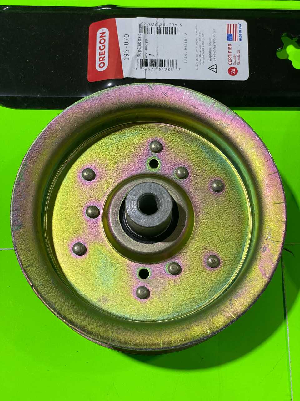
Each element within a hydraulic setup is interdependent, contributing to the entire assembly’s efficiency. A thorough understanding of these components enables effective troubleshooting and optimization. Visualizing Belt and Pulley SystemsBelt and pulley arrangements are fundamental components in mechanical engineering, enabling the transfer of power and motion between various machine elements. Understanding how these systems function can enhance efficiency and reliability in machinery. This section explores the intricacies of these assemblies, highlighting their significance in various applications. Key Components and Their FunctionsThe primary elements of belt and pulley systems include the belt, pulleys, and the driving mechanism. The belt serves as the link that transmits motion from one pulley to another. Pulleys, varying in size and shape, determine the speed and torque output of the system. The interaction between these components dictates the overall performance and effectiveness of the setup, making it crucial to grasp their individual roles. Applications in Modern MachineryThese systems are prevalent in numerous machines, ranging from simple devices to complex industrial equipment. They are widely used in automotive engines, conveyor systems, and various types of manufacturing equipment. By visualizing how belts and pulleys interact, one can better appreciate their importance in enhancing mechanical performance and operational efficiency. Tracking Lubrication System PartsUnderstanding the components of a lubrication system is essential for maintaining optimal performance and efficiency in machinery. Each element plays a vital role in ensuring that moving parts operate smoothly, reducing friction and wear. This section explores the key elements involved in lubrication management, focusing on their functions and importance. Essential Components
Maintenance and Monitoring
Regular inspection and upkeep of the lubrication system are crucial to prevent failures and prolong the lifespan of machinery. Key practices include:
Comparing Alternative Replacement Options
When considering various options for component substitutions, it is essential to evaluate multiple factors that can influence performance, compatibility, and cost-effectiveness. Many alternatives exist in the market, each offering unique features and benefits that may suit different needs. One critical aspect to analyze is the quality of the replacements. Some substitutes may provide enhanced durability or better performance under specific conditions, making them ideal for particular applications. Additionally, the availability of these alternatives can vary, impacting lead times and procurement processes. Price is another significant factor to consider when selecting substitutes. While some options may be more affordable, they may lack the reliability or longevity of premium alternatives. Therefore, balancing cost with performance is crucial for making informed decisions. Finally, it is beneficial to assess user reviews and testimonials for various replacement choices. Insights from other consumers can offer valuable perspectives on real-world performance and satisfaction, guiding potential buyers toward the best option for their needs. |


