When working with complex equipment, it’s crucial to have a clear understanding of how various mechanical elements interact with one another. Whether you are performing routine maintenance or addressing a specific issue, having a detailed visual reference of the essential connections and configurations can make the process smoother and more efficient.
Understanding the arrangement and alignment of key components helps ensure that each element is functioning properly within its assembly. By familiarizing yourself with the proper setup, you can avoid common pitfalls and enhance the longevity of the machinery.
This section provides a deep dive into the inner workings of crucial mechanical assemblies, offering insights into their structure and functionality. With this knowledge, you’ll be better equipped to identify potential issues and ensure the proper operation of the entire system.
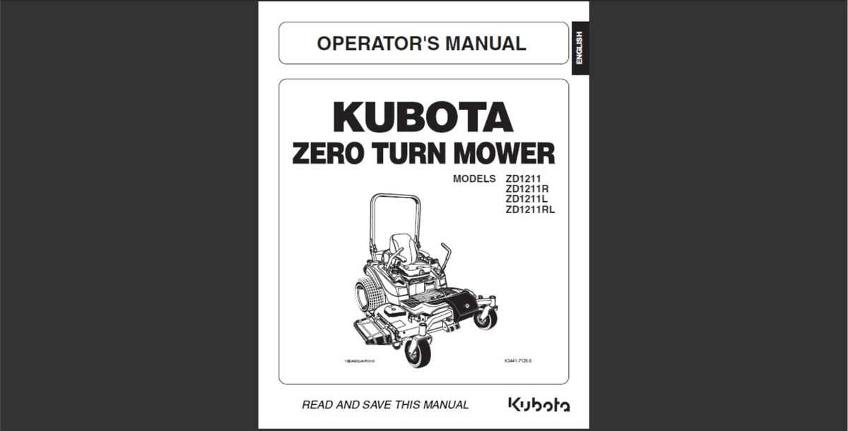
Overview of the Zd1211 Assembly
In this section, we will explore the main components and structure of this technical unit. By understanding the essential elements and how they fit together, you will gain a comprehensive perspective on how the system operates as a whole. This overview will help to clarify the key mechanisms and functional elements involved in the assembly process.
The system is designed with precision, ensuring each element contributes to its overall efficiency and performance. Various modules interconnect to form a cohesive structure, allowing the entire unit to perform complex tasks reliably. Through this breakdown, we aim to provide a clear understanding of the engineering behind the entire setup.
Each segment of the system plays a specific role, from the foundational base that supports the structure to the more intricate modules responsible for advanced functionality. The combination of these elements results in a robust and efficient operation, making the system both reliable and versatile in different applications.
Main Components of Zd1211
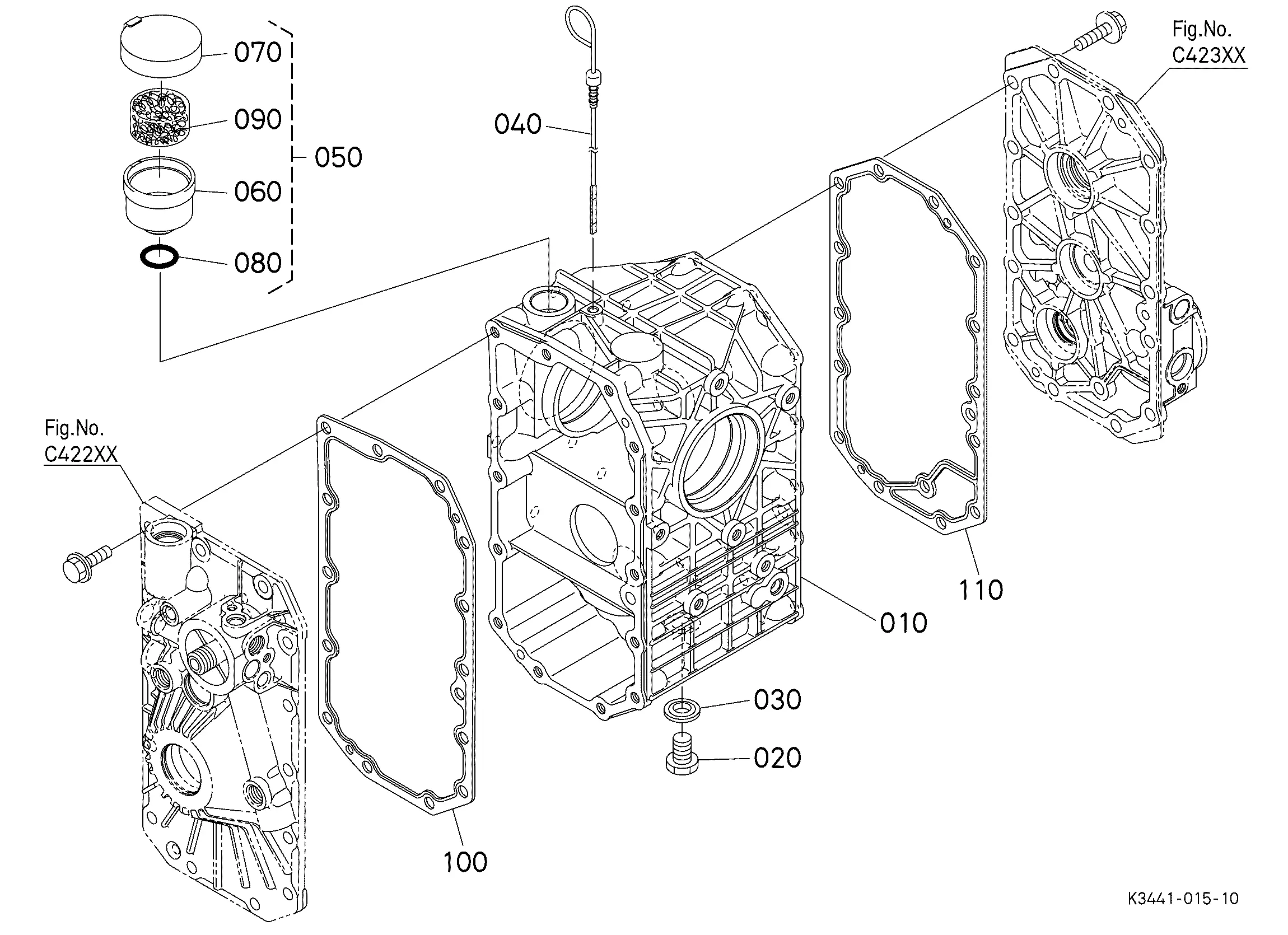
The device is built from several essential elements, each playing a critical role in its overall functionality. Understanding these key elements is fundamental for comprehending the full structure and operational logic of the unit.
- Core Processor Unit: This central element handles the primary computing tasks, processing data and managing all operations within the system.
- Communication Module: Responsible for data transfer, it ensures seamless interaction between the device and external systems or networks.
- Power Supply Unit: This section provides the necessary energy to maintain continuous operation, converting external power sources into usable formats.
- Input/Output Interfaces: These interfaces allow users or external devices to interact with the system, ensuring both data entry and command execution.
- Memory Components: Used to store both operational data and user inputs, these elements ensure the system can access and process information effectively.
- Circuit Protection Elements: These components safeguard the device from power surges and electrical faults, ensuring long-term reliability and durability.
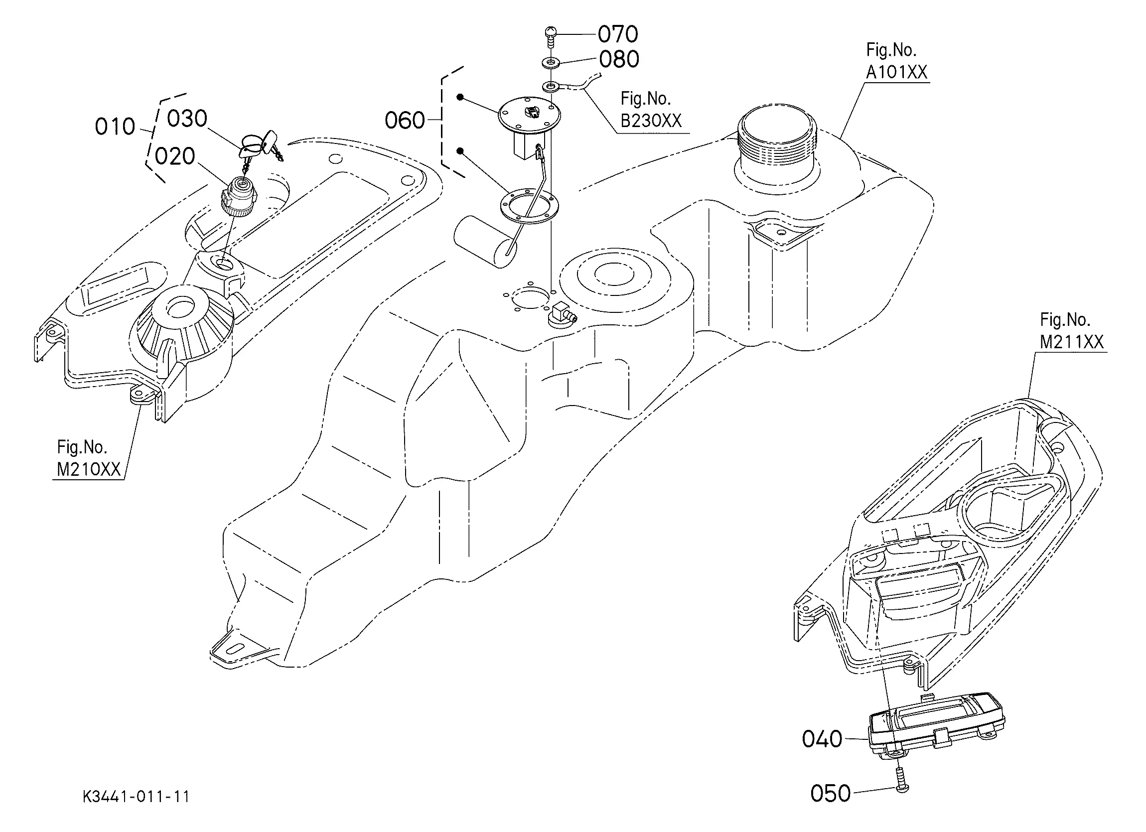
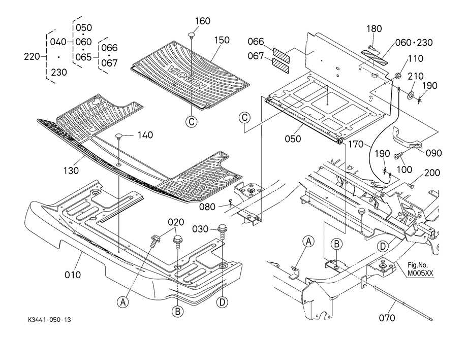
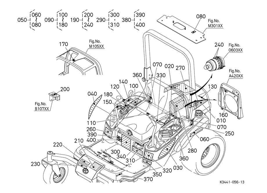
Exploded View of Zd1211
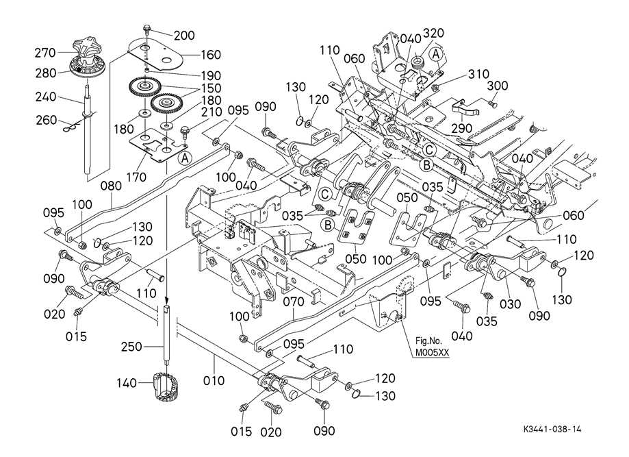
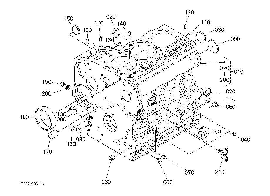
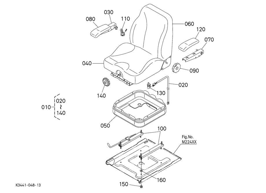
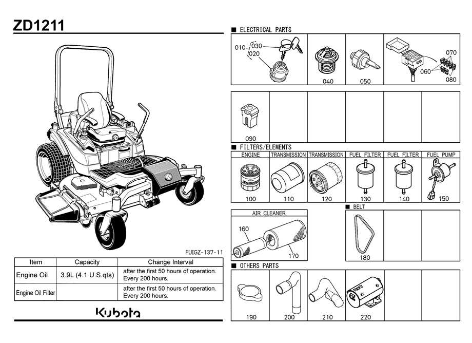
In this section, we will provide a detailed breakdown of the key mechanical and electrical components, arranged to show how each element fits into the overall system. This overview allows for a clear understanding of how individual elements connect and interact within the structure.
Main Assembly Overview
The system consists of multiple modules, each with a specific function that contributes to the entire mechanism’s operation. Below is a comprehensive table that lists and describes the primary modules, their function, and their interconnectivity.
| Component | Function | Location | ||||||||||
|---|---|---|---|---|---|---|---|---|---|---|---|---|
| Power Unit | Provides energy to drive the system | Base | ||||||||||
| Control Panel | Manages user input and system feedback | Front Section | ||||||||||
Drive Mechanism
Electrical Wiring Diagram for Zd1211
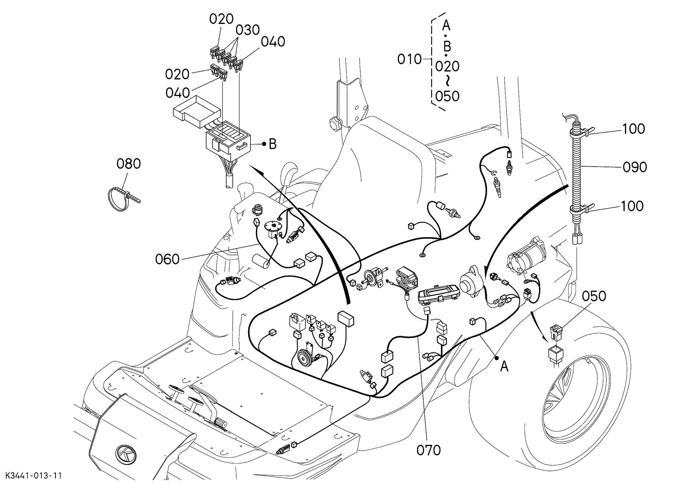
Understanding the layout of the electrical system is crucial for proper maintenance and troubleshooting. This section will outline the connections and pathways that ensure the efficient flow of power throughout the machine. By reviewing the key elements and their interconnections, users can gain insight into how electricity is distributed to different components, helping to diagnose potential issues and make informed decisions when repairs are needed. The electrical connections consist of several circuits responsible for distributing energy to critical areas such as the engine, control panel, and safety systems. Each of these circuits is interconnected through a series of fuses, switches, and relays, ensuring smooth and safe operation. Proper understanding of these linkages is essential for identifying faults in case of malfunction or during regular maintenance. Power is sourced from the battery, which is linked to the ignition system through various connectors and wires. These, in turn, connect to essential operational units, including lighting, the alternator, and any external attachments. Each connection point is designed for optimal safety and performance, providing reliable energy flow and protection Mechanical Parts Breakdown for Zd1211
The mechanical structure of this equipment consists of various interconnected components, each serving a crucial function in the overall operation. Understanding how these elements interact is essential for maintenance, repairs, and optimizing the performance of the machine. This section will outline the key elements involved, emphasizing their role and positioning within the system. Key Components and Their Roles
The core structure includes moving and static elements designed for durability and efficiency. Each element, whether responsible for motion or support, plays an integral role in the operation. The connections between them are engineered for maximum performance, ensuring that the system operates smoothly and reliably. Interconnected Systems
The machinery is built with an emphasis on cohesion between different mechanical sections. Each subsystem works in harmony to ensure the overall effectiveness of the device. Regular inspections and understanding the relationship between these elements are critical for long-term operation and reducing wear. Zd1211 Structural Frame Components
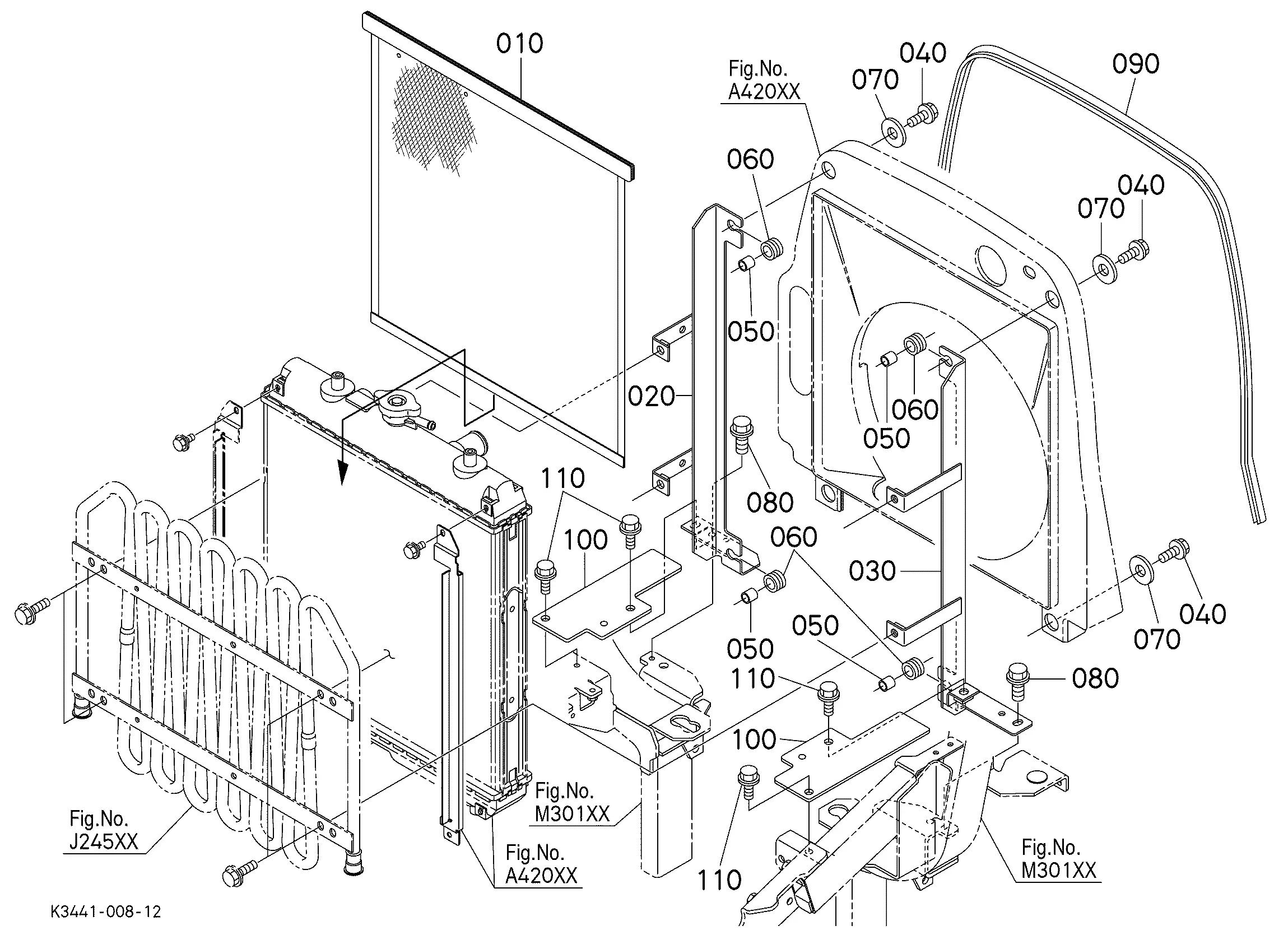
The structural framework of a device plays a crucial role in ensuring stability and durability. It consists of various interconnected elements that provide support and maintain the integrity of the overall system. These components are essential for holding other functional units in place, allowing smooth operation and effective performance. Each element is carefully designed to withstand physical stress while keeping the entire structure aligned and secure. Key components of the framework typically include the base, support brackets, and reinforcing plates. These parts form the foundation, offering strength and resistance to external forces. The joints and connectors between these pieces must be designed with precision to guarantee the assembly is robust and dependable. Together, these structural elements are vital for the longevity and functionality of the entire system. How Zd1211 Cooling System is Assembled
The cooling mechanism of this device is essential for maintaining optimal performance and preventing overheating during extended usage. It involves several key components working together in a carefully orchestrated sequence. The assembly process ensures each part is securely placed, contributing to the efficiency of heat dissipation and airflow management. Below is an overview of how these elements come together to create a functional and reliable cooling system.
Once these steps are followed, the assembly is complete, with all elements working in harmony to efficiently manage temperature. Regular maintenance and checking of these components will prolong the life and performance of the entire system. Zd1211 Internal Circuit Board Layout
The layout of an internal circuit board is crucial for the effective functioning of electronic devices. It provides the foundation for the various components and connections that ensure proper signal flow and power distribution. Understanding the arrangement of these elements can help in troubleshooting, maintenance, or upgrading of the system. In general, the circuit board houses several key sections that interact with one another. Each section is dedicated to specific tasks, such as power management, signal processing, and communication interfaces. The placement of components is often determined by the need for minimizing interference, optimizing performance, and managing heat distribution efficiently.
Key Moving Parts in Zd1211
Understanding the critical components that are responsible for motion in a mechanical system is essential for efficient operation. These elements play a pivotal role in ensuring that the equipment functions smoothly, providing the necessary movement for its intended purpose. Each moving element is meticulously designed to handle specific tasks, contributing to the overall performance and longevity of the machine. Drive Mechanism is one of the core systems that convert energy into motion. It typically includes gears, motors, and other elements that generate the force needed to move different sections of the assembly. Precision in this system ensures that the motion is consistent and reliable, even under varying loads. Rotating Components such as shafts and axles are also integral to the movement process. These parts are designed to rotate with high efficiency, transferring kinetic energy across various sections of the machinery. Their durability and smooth functioning are crucial for maintaining operational stability. Connecting Elements like linkages and levers serve to transmit force from one part of the system to another. These are essential for coordinating the actions of different sections, allowing them to work in harmony. Their design often incorporates flexible materials to accommodate varying levels of stress during operation. Control Mechanisms often involve sensors or actuators that manage the movement of specific components. They provide feedback to ensure that each part moves in the correct sequence and at the appropriate speed, thus maintaining precision and avoiding potential damage to the machine. Safety Mechanisms and ControlsEnsuring safety in electronic devices is crucial for their optimal performance and user protection. The incorporation of protective mechanisms helps prevent damage to the system, as well as safeguard users from potential hazards during operation. Various safety protocols are integrated to monitor and control different operational aspects of the equipment. These systems are designed to detect anomalies and trigger necessary actions before any damage occurs. Key Safety Features
Control Systems for Safe Operation
Maintenance Tips for Zd1211 Parts
Proper upkeep of your equipment’s components ensures optimal performance and prolongs their lifespan. Routine checks and careful attention to detail can prevent common issues that may arise from wear and tear. Regular maintenance not only improves efficiency but also helps in identifying potential problems early, saving time and costs in the long run. Regular Cleaning
Keeping all surfaces free of dust and debris is essential. Dirt buildup can cause friction and affect functionality, leading to unnecessary strain on the system. Use a soft cloth or air blower to clean the delicate areas, ensuring that no residue is left behind. Avoid harsh chemicals or abrasive tools that could damage sensitive surfaces. Check for Wear and TearOver time, some components may wear down due to constant usage. Inspect key elements for signs of damage, such as cracks, chips, or unusual noises. If any part appears compromised, it’s important to replace it immediately to avoid causing further damage. Paying attention to these small details can significantly enhance the longevity of the device. Pro Tip: It is recommended to lubricate moving parts to reduce friction and prevent premature wear. Use a manufacturer-approved lubricant to ensure compatibility and performance. |
