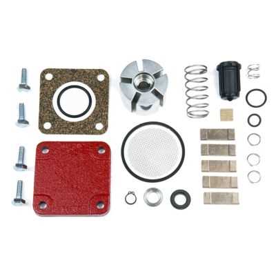
When dealing with complex machinery, it’s essential to grasp the overall structure and how individual elements contribute to the system’s performance. This section explores the critical components that ensure efficient operation and durability. By understanding the role of each element, users can maintain and troubleshoot the equipment more effectively.
Each piece within the mechanism plays a crucial role in ensuring smooth functionality. Regular inspection and maintenance of these elements are necessary to avoid breakdowns and extend the lifespan of the machinery. Here, we will delve into the core elements and their interconnected functions, providing a clear understanding for optimal operation.
Overview of Fill-Rite 15 GPM Pump
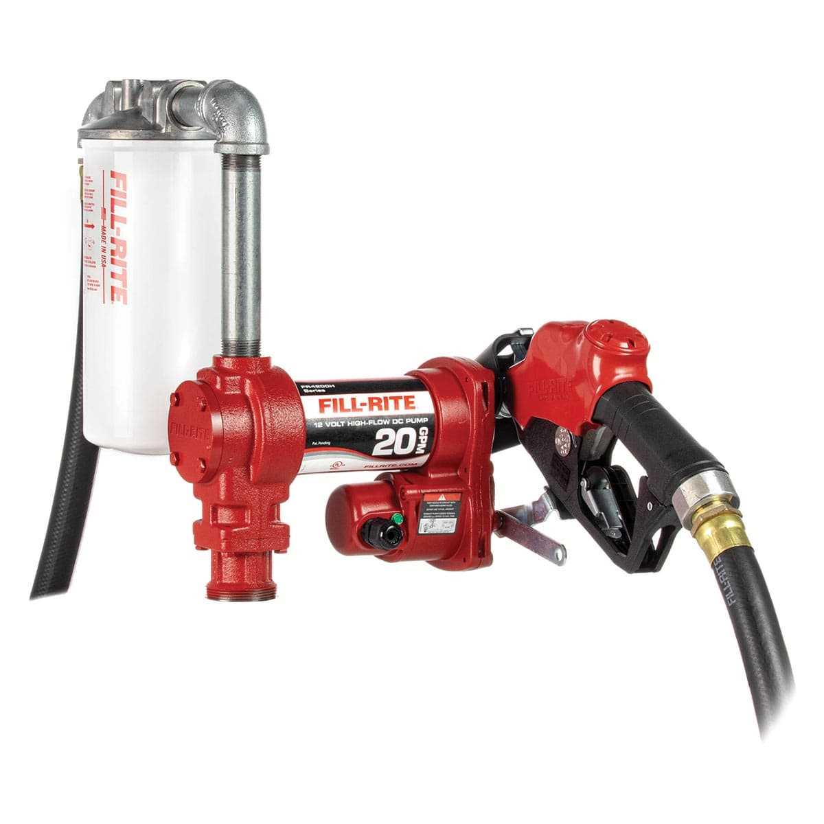
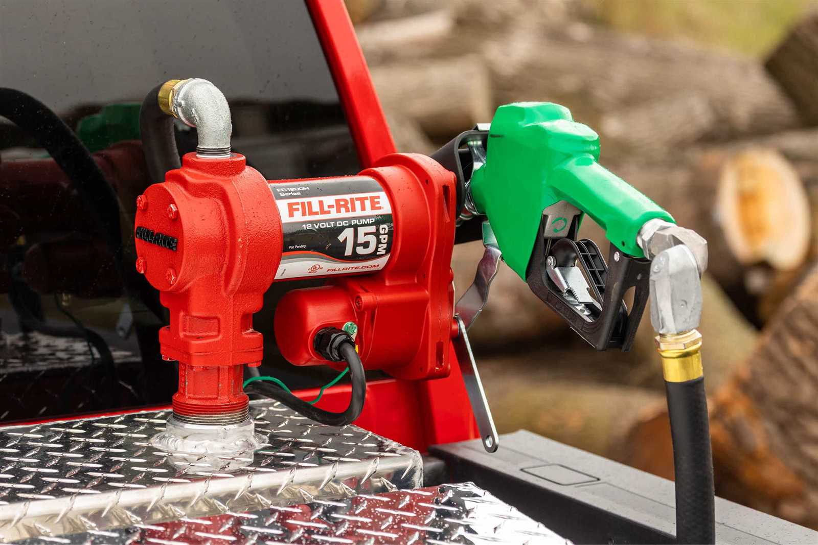
The equipment is designed for transferring liquid efficiently in various industrial settings. It ensures a reliable flow, making it a popular choice for those who require durable performance over extended periods.
This device comes with a variety of features that enhance its functionality. Its structure is built for handling demanding tasks, and the mechanism allows for consistent movement of substances with minimal effort.
- Sturdy construction for long-lasting use
- Engineered for efficient operation in harsh conditions
- Streamlined design for easy installation and maintenance
Its components are crafted to work in harmony, ensuring that the system operates smoothly even under significant stress. This makes it an ideal option for environments where dependability is key.
Main Components of the 15 GPM Pump
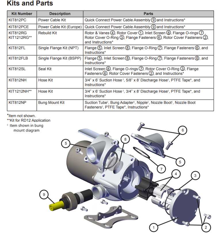
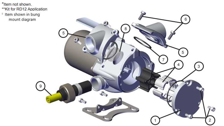
The mechanical system is composed of several critical elements that work in harmony to ensure the efficient transfer of liquids. Each element plays a vital role in maintaining proper functionality, contributing to the overall performance of the unit.
- Motor: The central power source that drives the entire operation. It converts electrical energy into mechanical movement.
- Housing: A sturdy enclosure that protects internal components from external damage and environmental factors.
- Impeller: A rotating device responsible for pushing liquid through the system, creating the necessary flow and pressure.
- Valves: Essential regulators that control the direction and flow rate of the liquid, ensuring smooth operation.
- Seals
Pump Body and Housing Features
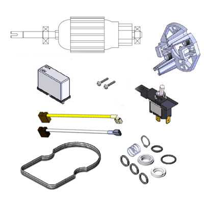
The main structure and enclosure are designed to provide durability and efficiency in various operational conditions. The robust outer frame ensures long-lasting performance and protects internal components from wear and environmental factors. This design allows the unit to function smoothly over extended periods, even in demanding situations.
Material and Construction
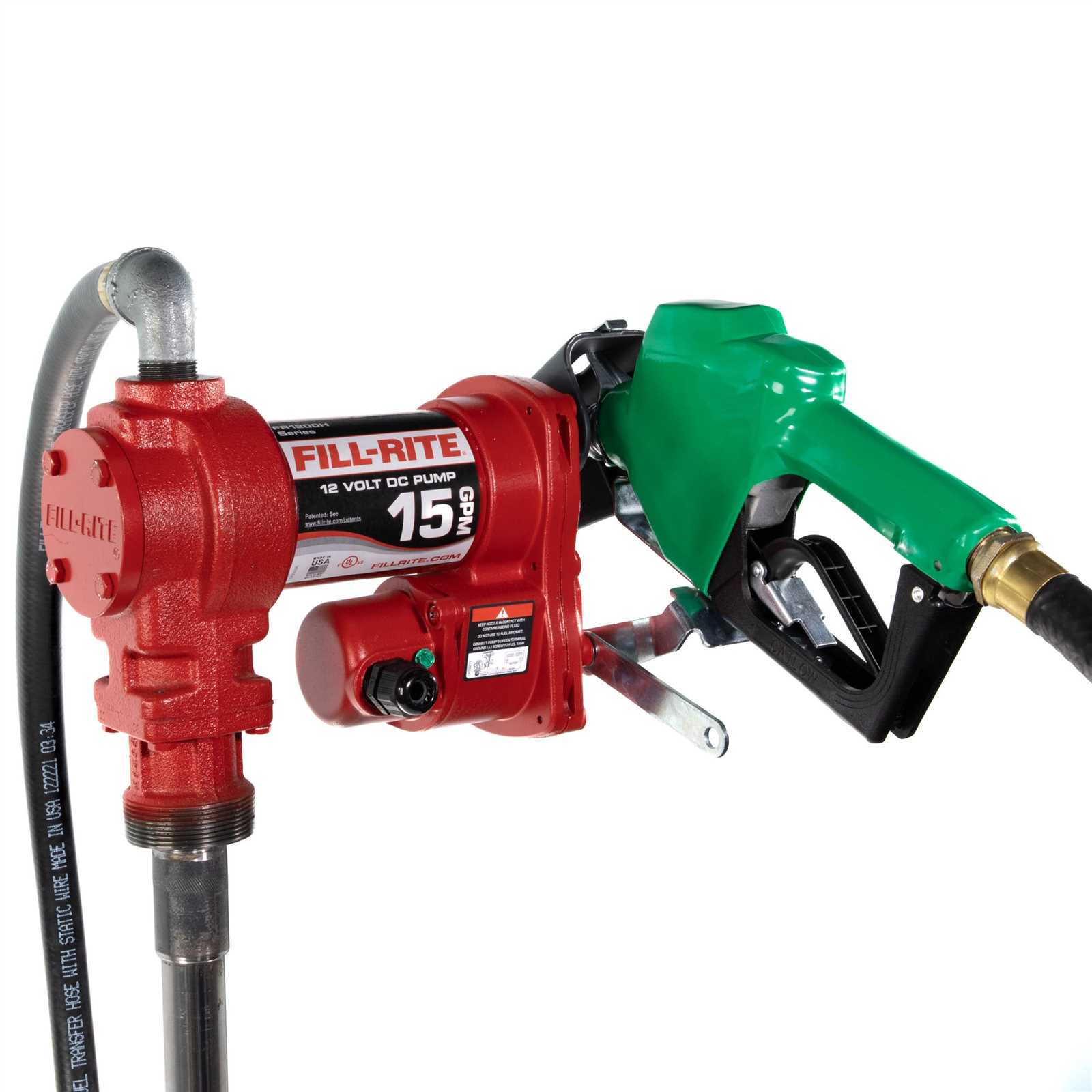
The casing is typically crafted from high-strength materials, offering excellent resistance to corrosion and mechanical stress. The choice of material ensures that the unit can withstand both chemical exposure and physical impacts, making it suitable for a variety of applications.
Sealing and Protection
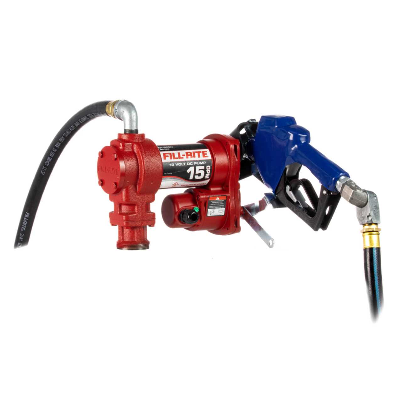
Special attention is given to sealing mechanisms, which prevent leakage and maintain the integrity of the internal system. The seals are carefully engineered to handle fluctuations in pressure and temperature, ensuring that the interior remains secure and free from external contaminants.
Internal Mechanism Layout and Function
The internal workings of the device are designed to convert rotational energy into fluid movement with precision. Each component plays a crucial role in ensuring smooth operation and efficient performance. Understanding the internal structure can help diagnose potential issues and enhance overall maintenance.
Main Internal Components
The primary parts within the system work together to control the flow and manage the pressure during operation. From rotary mechanisms to control valves, each element interacts to maintain consistent performance under various conditions.
Component Functions
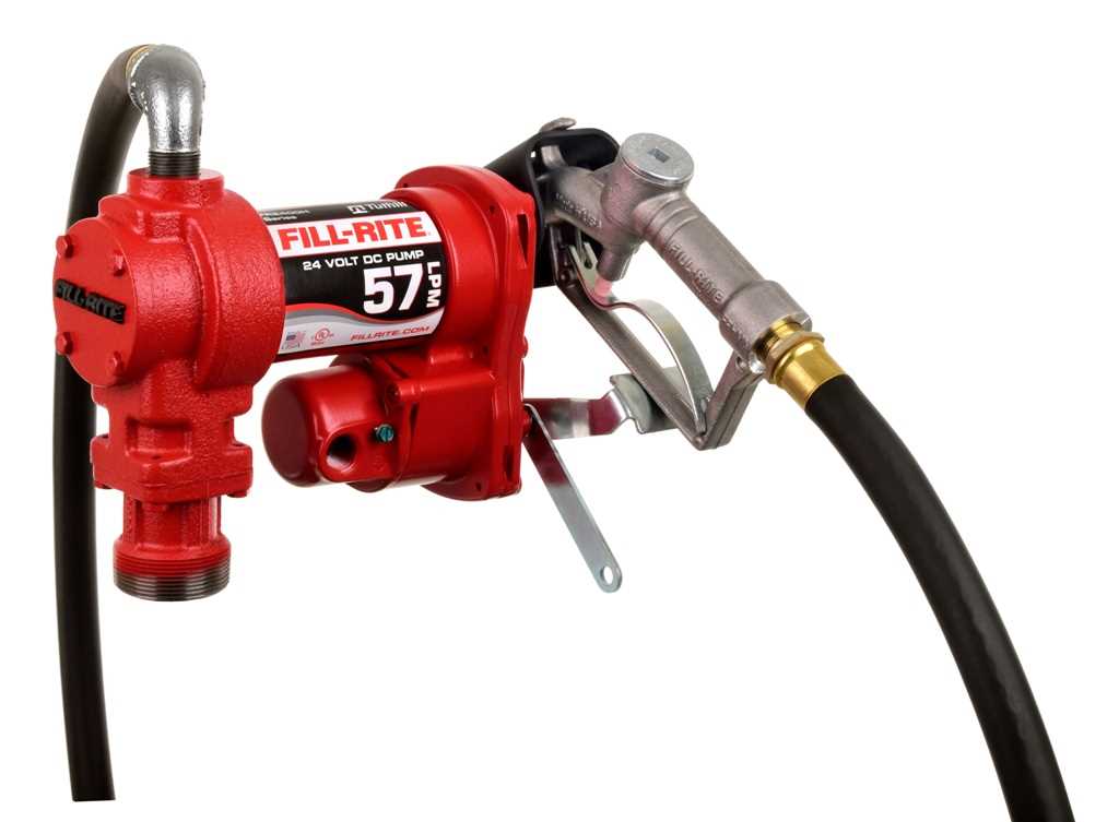
Each section of the internal mechanism is responsible for a specific task, such as controlling movement, regulating flow, or managing pressure. These components work in harmony to ensure the overall efficiency and longevity of the system.
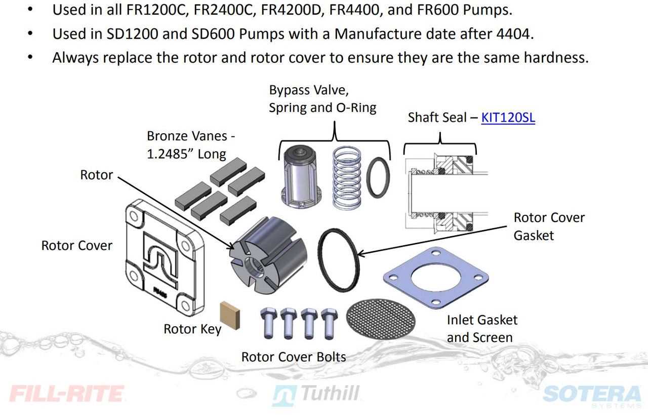
Component Function Rotary Mechanism Seal and Gasket Placement Details The correct alignment of seals and gaskets is essential for ensuring the proper functioning of any mechanical system. Each component must be placed with precision to prevent leaks, maintain pressure, and ensure long-term durability. Below is a breakdown of where these elements should be positioned for optimal performance.
Component Seal/Gasket Placement Inlet Valve Ensure the gasket fits tightly around the valve’s opening, providing a secure barrier against fluid seepage. Discharge Outlet The seal should be positioned around the perimeter of the outlet to maintain pressure and avoid leaks. Motor Assembly Breakdown
This section provides an overview of the various components that comprise the motor assembly of a fuel transfer device. Understanding these elements is essential for effective maintenance and troubleshooting, ensuring optimal performance and longevity of the unit.
The motor assembly is made up of several key components that work together seamlessly. Each part plays a vital role in the overall functionality and efficiency of the mechanism.
Component Description Motor Housing Encases the motor and protects internal components from external elements. Rotor Drives the mechanism by converting electrical energy into rotational motion. Stator Stationary part that generates a magnetic field, essential for motor operation. Shaft Connects the rotor to the output mechanism, enabling the transfer of motion. Bearings Support the shaft and allow for smooth rotation, reducing friction. Inlet and Outlet Valve Configuration
The arrangement of entry and exit valves plays a crucial role in the functionality of fluid transfer systems. Proper configuration ensures efficient flow, minimizes pressure loss, and enhances overall performance. Understanding how these components interact is essential for optimizing operational efficiency and reliability.
Functionality of Entry and Exit Valves
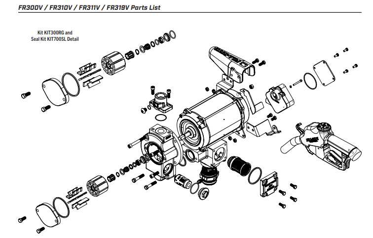
Entry valves are responsible for controlling the inflow of liquid, while exit valves manage the discharge. The effectiveness of these mechanisms can significantly influence the system’s capability to maintain consistent pressure and flow rates. Ensuring that both types of valves are appropriately calibrated is vital for achieving optimal performance.
Common Configurations
Several configurations can be utilized for entry and exit valves, each designed to cater to specific requirements. Below is a table outlining some of the typical arrangements and their respective advantages:
Configuration Type Description Advantages Single Entry Single point of liquid entry. Simplicity and ease of maintenance. Double Entry Two entry points for enhanced flow control. Improved efficiency and reduced cavitation risk. Check Valve Prevents backflow in the system. Increased safety and reliability. Hose and Nozzle Compatibility
When selecting hoses and nozzles for fluid transfer systems, it is crucial to ensure they are compatible with each other. Proper compatibility enhances efficiency and reduces the risk of leaks or malfunctions. The materials, dimensions, and design of these components play a significant role in their performance.
Material Considerations
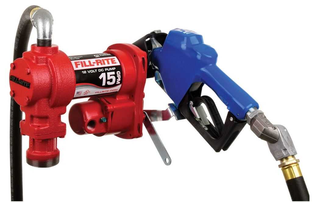
Different fluids require specific materials for hoses and nozzles to avoid degradation. For instance, certain chemicals can corrode traditional materials, leading to failures. It’s important to select components made from appropriate materials that can withstand the intended fluid.
Dimension and Fitting Standards
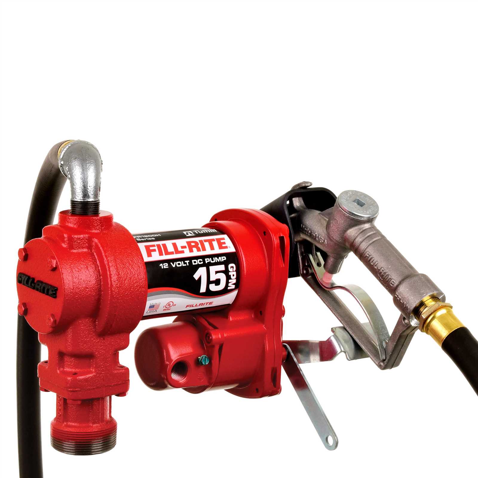
The dimensions and fitting standards of hoses and nozzles must align to ensure a secure connection. Mismatched sizes can cause leaks or inefficiencies in fluid transfer. Always verify that the diameter and fitting type of both components are compatible.
Component Type Recommended Material Typical Diameter (inches) Hose Polyurethane 1 Nozzle Aluminum 1 Hose Rubber 0.5 Nozzle Plastic 0.5 Filter and Strainer System

The filtration and straining assembly is crucial in maintaining the efficiency and longevity of fluid transfer systems. This setup plays an essential role in ensuring that only clean, contaminant-free liquids pass through the system, thereby protecting the internal components from damage and wear.
Key components of this system typically include:
- Filters: Devices designed to remove impurities from liquids. They can be of various types, including mesh, cartridge, and coalescing filters.
- Strainers: Instruments used to capture larger particles before they enter more sensitive parts of the system. They help prevent blockages and reduce maintenance frequency.
- Housings: Structures that enclose filters and strainers, providing a secure environment for efficient operation.
Proper selection and maintenance of these elements are vital. Consider the following best practices:
- Regular inspection of filters and strainers for clogs or damage.
- Replacement of filter elements as per the manufacturer’s recommendations.
- Choosing the appropriate filter and strainer types based on the specific application and fluid characteristics.
Implementing a well-designed filtration and straining system will greatly enhance the overall performance and reliability of fluid handling processes.
Switches and Control Elements
In any fluid transfer system, the functionality and efficiency of operation are heavily reliant on the various control mechanisms utilized. These elements play a crucial role in regulating flow, monitoring performance, and ensuring safety. A well-designed control system allows for precise management of fluid transfer processes, enhancing overall productivity and user experience.
Types of Control Mechanisms
Control elements can be classified into several categories, each serving specific purposes within the system. Here are some common types:
Type Description Pressure Switches Devices that activate or deactivate based on pressure levels, ensuring the system operates within safe parameters. Flow Sensors Instruments that measure the rate of fluid movement, providing essential feedback for process control. Control Valves Mechanisms that regulate the flow of fluid by opening or closing in response to signals from control systems. Emergency Shut-off Switches Safety features that allow for immediate termination of operations during unforeseen circumstances. Importance of Reliable Controls
Utilizing dependable switches and control elements is vital for maintaining operational integrity and safety in any fluid handling application. Properly functioning controls not only enhance performance but also significantly reduce the risk of accidents and failures. Ensuring the reliability of these components is essential for a seamless and safe operational experience.
Maintenance Points and Wear Parts
Regular upkeep of your fluid transfer device is essential for optimal performance and longevity. Identifying key areas that require attention can significantly reduce the risk of malfunction and ensure smooth operation. Properly managing wear components will help maintain efficiency and prevent costly repairs.
Here are some critical maintenance aspects to consider:
Component Maintenance Frequency Replacement Indicators Seals Every 6 months Visible wear, leaks Filters Monthly Clogging, reduced flow Hoses Annually Cracks, bulges Motor Every 3 months Unusual noises, overheating Gaskets Every 6 months Leaking, degradation By adhering to these maintenance guidelines and promptly addressing any signs of wear, you can significantly extend the lifespan of your fluid handling system and ensure its reliable operation.
Troubleshooting Common Issues
Addressing typical challenges encountered with fluid transfer equipment is crucial for maintaining efficient operation. Identifying and resolving these problems can help ensure optimal performance and longevity of the machinery.
Identifying Common Problems
- Inconsistent flow rates
- Unusual noises during operation
- Leakage around connections
- Excessive vibrations
Steps to Resolve Issues
- Check all connections and fittings for tightness to prevent leaks.
- Inspect for any obstructions in the inlet or outlet that may hinder flow.
- Examine the power source to ensure it is providing adequate energy.
- Listen for irregular sounds and identify potential sources, such as damaged components.