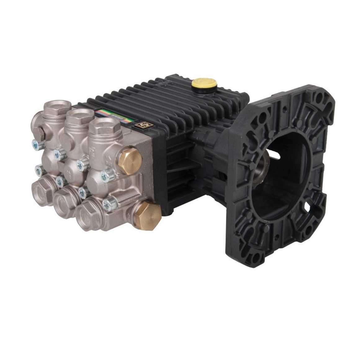
| Primary Seal |
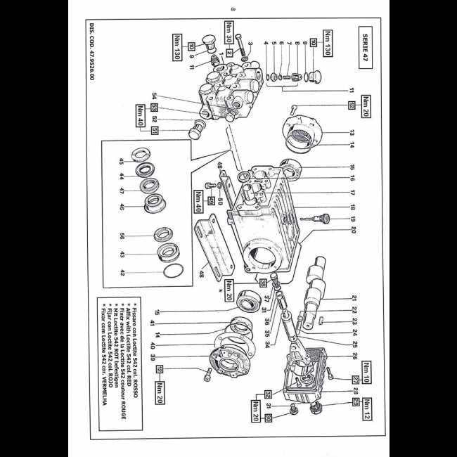
Guide to Identifying Bearing Locations
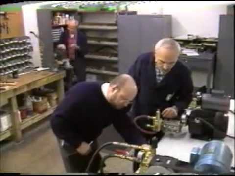
Recognizing the correct positioning of bearings is essential for maintaining optimal functionality in various mechanical systems. Bearings play a crucial role in reducing friction and supporting rotational elements, ensuring smooth operation and longevity of the equipment.
- Begin by locating all major rotational components in the system. Bearings are typically situated near these moving parts.
- Check areas where shafts meet the housing or other stationary elements. These junctions often require bearings to reduce wear and maintain alignment.
- Look for mounting points, brackets, or supports where rotating parts are fixed. Bearings are frequently installed in these locations to allow for controlled movement.
- In some assemblies, protective covers or seals may hide the bearings. Remove these carefully to access the bearing positions.
Identifying the exact bearing location is critical for both maintenance and repair procedures, as improperly positioned bearings can lead to premature failure or damage
Inlet and Outlet Manifold Structure
The configuration of the inlet and outlet components plays a crucial role in the performance and efficiency of hydraulic systems. These structures facilitate the flow of fluid, ensuring optimal pressure and minimizing turbulence. Understanding their design helps in maintaining the system and enhancing its functionality.
Key Components
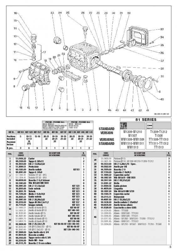
- Inlet Ports: These allow fluid entry into the manifold.
- Outlet Ports: Designed for fluid exit, ensuring smooth discharge.
- Flow Channels: Pathways that direct fluid through the manifold.
- Sealing Mechanisms: Prevent leaks and ensure secure connections.
Functionality and Importance
The inlet and outlet manifold structures serve to optimize fluid dynamics within the system. Their proper functioning is essential for:
- Maintaining consistent pressure levels.
- Enhancing the overall efficiency of fluid transfer.
- Reducing wear on other system components.
Piston Rod and Cylinder Layout Details
The configuration of the piston rod and cylinder plays a critical role in the performance and efficiency of hydraulic systems. Understanding the arrangement of these components is essential for effective maintenance and troubleshooting.
Design Specifications
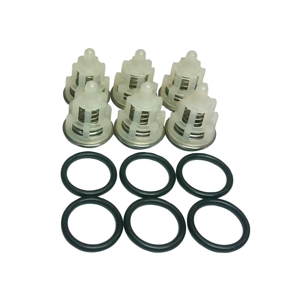
The design encompasses the dimensions and materials used for both the piston rod and the cylinder. A well-designed rod typically features a smooth surface to minimize friction, while the cylinder must be durable to withstand high pressure. The alignment between these parts is vital to ensure optimal movement and reduce wear over time.
Operational Insights
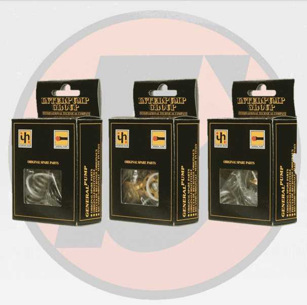
During operation, the piston rod extends and retracts within the cylinder, creating the necessary force for various applications. Proper lubrication is essential to maintain efficiency and longevity. Regular inspections can help identify any misalignments or damage that could affect the system’s overall functionality.
Unloader Valve System Configuration
The unloader valve plays a crucial role in managing pressure within hydraulic systems. Its primary function is to regulate the flow of fluid and prevent over-pressurization, thereby ensuring optimal performance and safety. Understanding its configuration is essential for effective operation and maintenance.
| Component |
Description |
| Spring |
Provides resistance and controls the valve opening pressure. |
| Ball Seat |
Holds the ball in place, ensuring a tight seal when closed. |
| Adjustment Screw |
Allows for fine-tuning of the pressure settings. |
| Bypass Port |
Enables fluid to flow back to the tank when pressure exceeds a set point. |
| Ball |
Closes off the flow path when the system is under pressure. |
Oil Seal Positioning and Maintenance
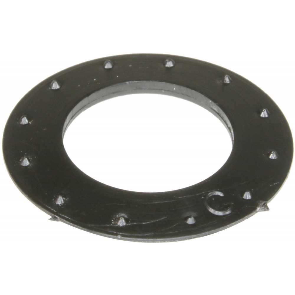
Proper placement and upkeep of sealing elements are crucial for ensuring the longevity and efficiency of machinery. These components serve as barriers against contaminants, preventing fluid leakage and maintaining optimal performance. Understanding the correct installation and maintenance practices can significantly enhance the durability of the equipment.
When positioning sealing elements, it is essential to follow specific guidelines to avoid premature wear and potential failure. Incorrect installation can lead to misalignment, which compromises the integrity of the seal.
| Step |
Description |
| 1 |
Clean the sealing area thoroughly to remove any debris or old seal remnants. |
| 2 |
Apply a thin layer of lubricant to the seal’s outer surface to facilitate easier insertion. |
| 3 |
Align the seal carefully with the housing, ensuring it is positioned evenly around the circumference. |
| 4 |
Press the seal into place gently, avoiding any twisting or distortion that could damage it. |
| 5 |
Inspect the installation for any visible gaps or misalignments before reassembling the equipment. |
Regular inspection and maintenance of sealing elements are vital for detecting wear and preventing leaks. Replacing seals at the first signs of damage can save costs and enhance machinery efficiency.
O-Rings and Gaskets Placement Map
This section outlines the arrangement and positioning of sealing components critical for maintaining the efficiency and integrity of hydraulic systems. Proper placement ensures optimal performance and prevents leaks.
Below is a guide to the correct locations for various sealing elements:
- Identify the key junctions in the assembly where seals are required.
- Refer to the corresponding numbered sections to understand the specific placements.
- Ensure that the grooves are clean and free from debris before installation.
Follow these recommendations for proper installation:
- Begin with the largest sealing rings at the main junctions.
- Proceed to install smaller gaskets in the designated areas.
- Double-check the alignment of all components before final assembly.
Regular maintenance checks should include inspecting these seals to prevent operational failures.
Discharge Assembly and Flow Paths Explanation
The discharge assembly plays a crucial role in the efficient operation of fluid systems, facilitating the movement of liquids from one section to another. Understanding the flow paths within this assembly is essential for optimizing performance and ensuring effective operation.
Components of the Discharge Assembly
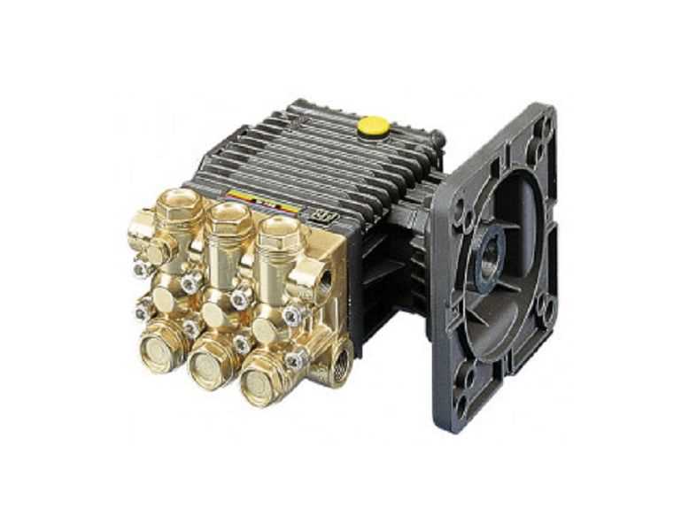
The discharge assembly consists of several key elements that contribute to its functionality:
- Housing: Encloses the internal components and provides structural support.
- Check Valves: Prevent backflow and ensure one-directional flow.
- Pressure Relief Valves: Regulate pressure levels to prevent system overload.
- Piping: Directs the flow of fluids to the desired outlet.
Flow Path Dynamics
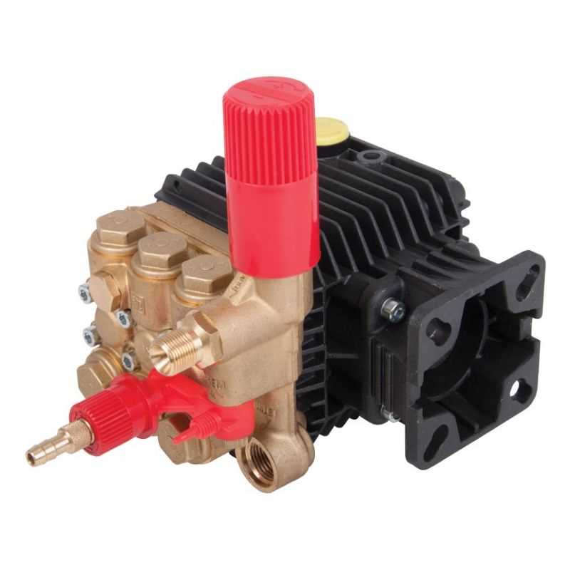
The flow paths within the discharge assembly are designed to maximize efficiency and minimize turbulence. Key aspects include:
- Entry Point: Where the fluid enters the assembly.
- Distribution Channels: Direct the flow toward the necessary outlets.
- Exit Point: The final destination where the fluid is discharged.
Understanding these components and flow dynamics is vital for effective maintenance and troubleshooting of fluid systems.
