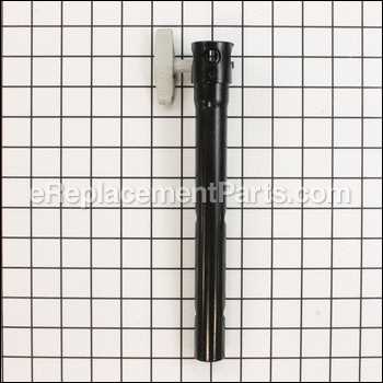
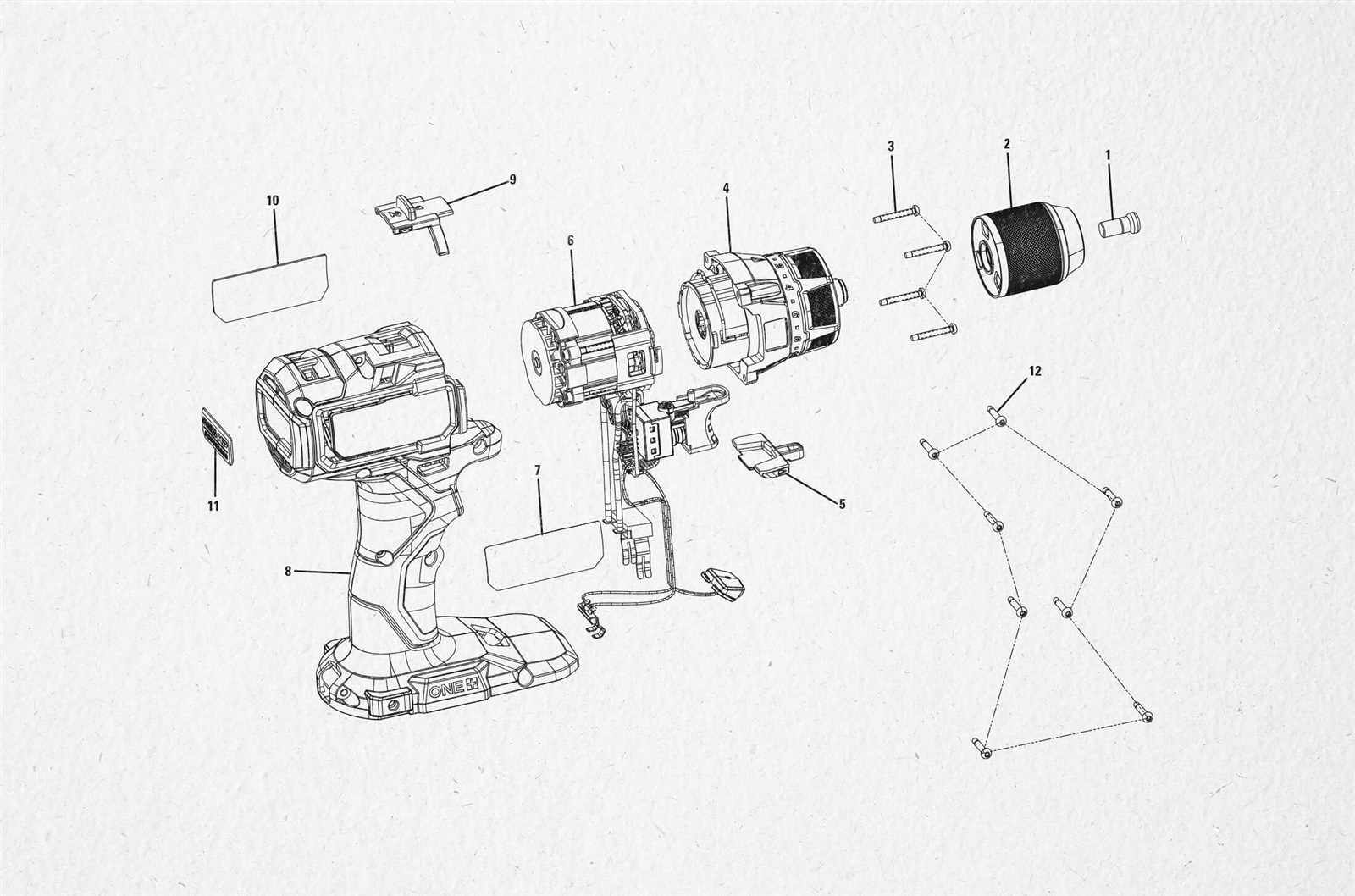
The inner workings of various devices often rely on a combination of crucial elements that together ensure optimal performance. Learning how these elements are arranged and how they interact can be essential for both maintenance and troubleshooting. A closer examination of these components provides valuable insights into their roles and relationships within the system.
Whether you’re dealing with an everyday tool or a specialized piece of equipment, the ability to recognize and understand the connections between different elements can help in identifying any potential issues. This process becomes especially relevant when trying to enhance performance, make adjustments, or replace key elements that might be worn or damaged over time.
By familiarizing yourself with how each component fits into the overall design, it’s possible to carry out more effective repairs and ensure that the equipment continues to operate at peak efficiency. The following sections will offer a detailed breakdown of the essential elements, their positioning, and their respective purposes.
Understanding the Components of Ryobi ry40002
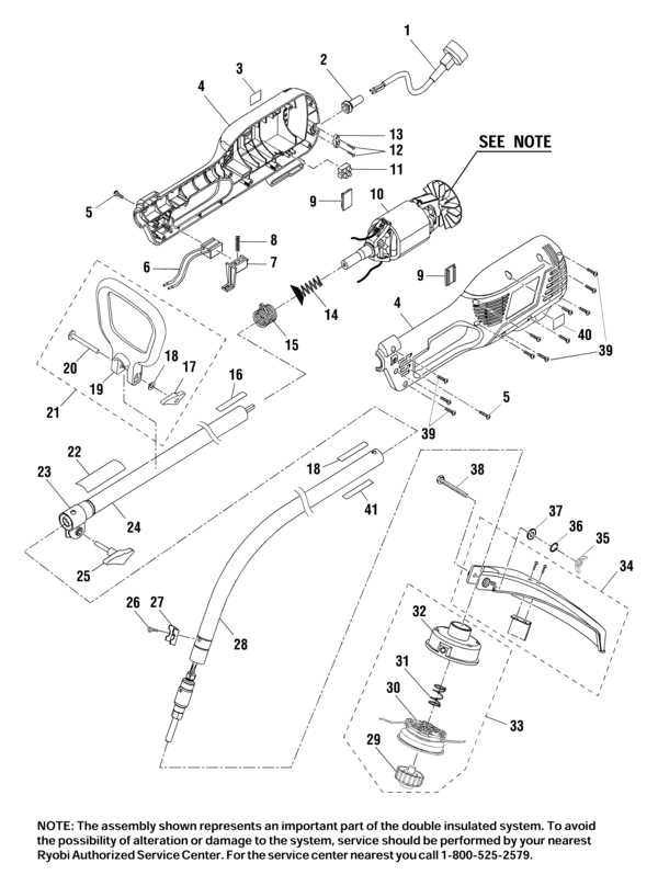
Exploring the essential elements of this tool is crucial for users who want to ensure proper maintenance and longevity. Each piece plays a significant role in the overall operation, contributing to the efficiency and reliability of the equipment. Familiarity with the internal and external structures is key to optimizing its use and addressing any potential issues that may arise.
Main Structural Elements
The primary frame consists of sturdy materials designed to withstand heavy use. Its central housing protects the motor and other vital mechanisms, ensuring durability during extended operation. Additionally, ergonomic handles are crafted to provide comfort during prolonged tasks, reducing fatigue for the user.
Key Mechanical Features
Inside, the motor is the powerhouse, driving the motion and providing the necessary force for operation. Various smaller components
Overview of Key Ryobi ry40002 Elements
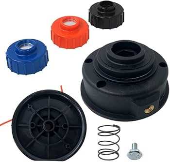
Understanding the main components of this versatile tool is essential for ensuring optimal performance and ease of maintenance. The design incorporates a variety of interconnected elements that work together to provide efficiency and durability in various tasks. By familiarizing oneself with these elements, one can enhance the tool’s functionality and prolong its lifespan.
Primary Structural Components
The tool’s main framework provides a robust and lightweight build, ensuring it remains easy to handle during operation. Key structural elements include the handle, which offers ergonomic support, and the housing, designed to protect internal mechanisms from external damage. Additionally, secure mounting points allow for easy attachment of various accessories.
Essential Mechanical Features
The internal mechanics drive the overall operation, featuring components responsible for power transmission and precise control. The motor plays a critical role in generating energy, while specialized gears and shafts ensure smooth operation. These parts are engineered to withstand wear, making them reliable
Identifying Major Assemblies and Their Functions
Understanding the main components of any mechanical device is key to proper maintenance and troubleshooting. Each unit is composed of several key sections that work together to ensure functionality and efficiency. Identifying these assemblies helps users comprehend how the device operates as a whole and what role each part plays in the overall mechanism.
- Motor Assembly: This section drives the entire system, converting electrical energy into mechanical motion. It typically consists of various internal parts that ensure consistent power output.
- Transmission System: The transmission ensures that power from the motor is delivered to the necessary components, controlling speed and torque. Its role is crucial for adjusting performance under different conditions.
- Control Unit: The control unit allows
Detailed Breakdown of Motor Components
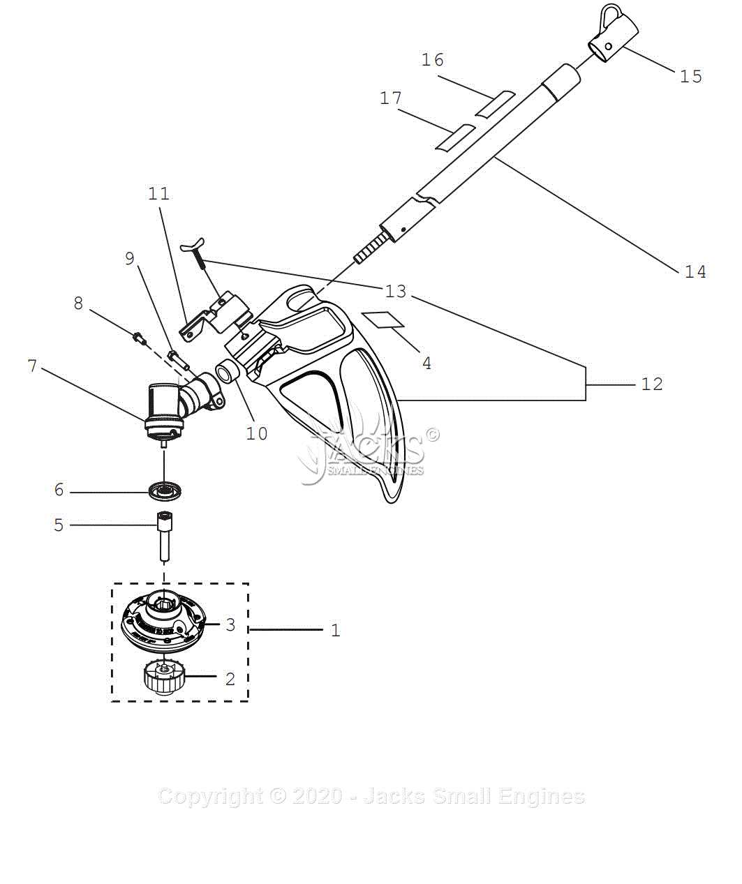
The inner workings of the motor involve a combination of interconnected mechanisms that drive its function. Each element is designed to work harmoniously, converting electrical energy into mechanical motion, ensuring smooth and efficient operation. This section provides an overview of the core components, explaining how they contribute to the overall system and enhance performance.
Rotor and Stator Interaction
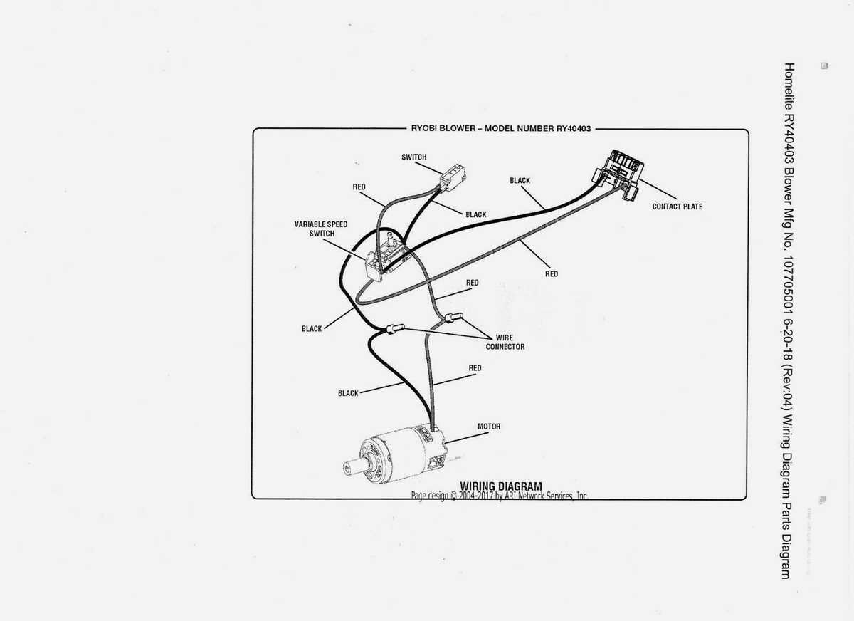
At the heart of the motor lies the interaction between the rotor and stator. The rotor, which rotates within the device, is crucial for generating motion. It operates in conjunction with the stationary stator, whose magnetic field creates the necessary force to spin the rotor. Together, these elements form the basis of the motor’s mechanical energy output.
Winding and Bearings
The winding is a key component responsible for producing the magnetic field when electrical current passes through. These tightly wound coils surround the stator,
Battery System and Power Source Configuration
The power delivery mechanism plays a critical role in ensuring consistent and efficient operation of devices. This system is designed to provide a stable energy flow, allowing the equipment to perform at its best without interruptions. Understanding the configuration of the power source and its interaction with the energy storage unit is essential for maintaining optimal functionality and extending the lifespan of the system.
Here are some key components and considerations of the energy setup:
- Energy Storage Unit: A crucial element that stores the necessary charge to keep the device operational over extended periods. It ensures a constant energy supply, even when direct power is unavailable.
- Charging Mechanism: A system designed to replenish the stored energy efficiently, ensuring the energy unit remains ready for use. It typically operates
Exploring Handle and Grip Mechanisms
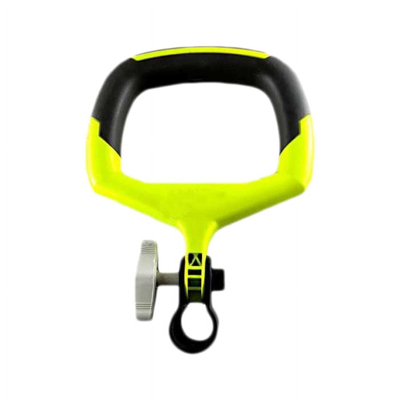
The design and functionality of the handle and grip play a crucial role in ensuring comfort and control during operation. These elements are essential for providing users with a firm hold, reducing fatigue, and maintaining precision. A well-designed grip can make a significant difference in the overall experience, enhancing both safety and performance during use.
Key Features of Handle and Grip Systems
Effective handle and grip mechanisms are designed to meet both ergonomic and durability standards. The materials used for the grip often offer resistance to wear and provide a non-slip surface, ensuring a secure hold even under challenging conditions. Moreover, the handle itself is crafted to suit various hand sizes, contributing to better handling and maneuverability.
Feature Benefit Non-slip surface Improves grip in wet or oily conditions Ergonomic design Reduces strain and enhances comfort during extended use Durable materials Ensures longevity and maintains grip quality over time Customizable fit Adapts to various hand sizes for better control Impact of Grip Design on Performance
The grip design directly influences the precision and efficiency with which tools are operated. A well-fitted handle enables the user to maintain a steady posture, minimizing the risk of hand fatigue and allowing for prolonged use without discomfort. Additionally, the grip’s texture and shape can offer a more controlled application of force, increasing accuracy and reducing the chance of mishandling.
Trigger and Control Switch Mechanism Analysis
The trigger and control system within power tools is essential for efficient operation and user control. It governs the activation and regulation of the tool’s motor, ensuring the right amount of power is delivered in response to the user’s input. Understanding how this system functions can help in troubleshooting, maintenance, and improving overall tool performance.
At the heart of the control system lies the trigger mechanism, which serves as the primary interface for the user. This mechanism is responsible for initiating the tool’s operation and adjusting speed or power based on the amount of pressure applied. Alongside the trigger, the control switch provides an additional layer of functionality by enabling specific modes or safety features.
- Trigger mechanism: Typically, a spring-loaded component that engages the motor once activated. Its design ensures a smooth transition between on and off states.
- Control switch: A secondary switch, often integrated into the trigger assembly, that allows the user to manage different operational settings such as variable speed or reverse functions.
- Safety features: Many tools incorporate safety mechanisms, like a lockout switch, that prevent accidental activation, enhancing both user safety and tool longevity.
Analyzing the interaction between these components reveals a system designed for precision and durability. By focusing on the trigger and control switch, manufacturers aim to optimize the balance between user comfort and tool performance.
How the Drive Shaft Mechanism Operates
The drive shaft is a crucial component responsible for transmitting power from the motor to other essential parts of the machine. It converts rotational energy into mechanical force, ensuring smooth operation of the device. This mechanism plays a vital role in maintaining efficiency and performance during use.
Typically, the drive shaft mechanism consists of a series of interconnected elements that work in unison to transfer motion. These components include the shaft itself, bearings, and couplings that help maintain alignment and reduce friction, allowing the transfer of energy to be as smooth and efficient as possible.
Component Function Drive Shaft Transfers rotational power from the motor to other parts of the machine Bearings Support the shaft and reduce friction, ensuring smooth rotation Couplings Connect the drive shaft to other parts, allowing for the transfer of motion Each of these elements must work efficiently to ensure that power is transferred accurately and without any energy loss. A well-maintained drive shaft mechanism ensures optimal performance and extends the lifespan of the equipment.
Blade Housing and Guard Structure Details
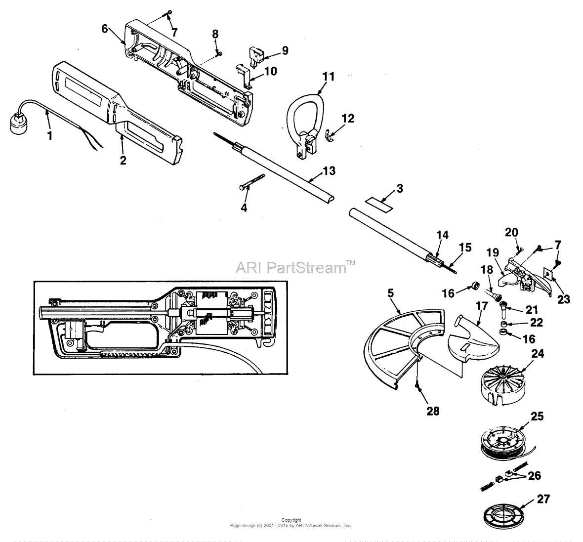
The blade housing and protective guard play crucial roles in ensuring the safety and efficiency of cutting tools. These components are designed to securely encase the blade while allowing optimal operation. Their primary function is to offer protection against accidental contact with the sharp edges of the blade, while also facilitating smooth movement during use. The overall structure is carefully engineered for durability and precision in various tasks.
Blade Housing Design
The blade housing is constructed to fit tightly around the cutting blade, providing stability and preventing movement during operation. It is typically made from robust materials such as high-impact plastic or metal alloys, ensuring resistance to wear and tear. The design of the housing is essential for minimizing vibrations and enhancing the performance of the tool. It allows for easy access to the blade when necessary, yet remains securely in place during cutting.
Guard Structure and Function
The protective guard is an integral part of the tool’s safety system. It surrounds the blade to shield users from potential accidents. Typically, the guard is adjustable, allowing it to move in tandem with the blade’s movement, ensuring continuous protection. Its design also ensures that debris and dust are effectively contained, improving visibility and reducing the risk of injury. A well-designed guard is not only a safety feature but also contributes to the overall balance and ergonomics of the tool.
Connection Points and Fastening Hardware
When assembling or maintaining any mechanical device, understanding the connection points and securing components is essential for optimal performance. These elements ensure that all parts are firmly in place, preventing malfunctions or potential damage. Proper fastening hardware contributes to the overall durability and stability of the system, allowing each part to work in harmony.
Connection points are the areas where different components meet and interact. These junctions are typically designed to ensure a tight fit, facilitating smooth movement or transfer of power. Each point plays a crucial role in distributing stress evenly, thus enhancing the lifespan of the equipment.
Fastening hardware includes various types of screws, bolts, nuts, and clips that are used to secure parts together. Choosing the right fastening methods is key to ensuring that all elements stay in position, even under stress or vibrations. The correct selection of hardware not only makes assembly easier but also strengthens the overall structure.
Maintenance Guide for Ryobi ry40002 Parts
Proper upkeep of your equipment ensures its longevity and optimal performance. Regular maintenance is essential to avoid premature wear and tear and maintain efficient operation. This guide covers essential tasks for keeping your tool in peak condition, focusing on key components that need attention over time.
Routine Cleaning and Inspection
To prevent build-up of debris and other materials, it is crucial to perform regular cleaning. Inspect the different sections for wear or damage, ensuring that all moving parts function smoothly. Dirt and dust can compromise the performance, so keeping components clean is a top priority. Pay attention to the following areas:
Component Maintenance Task Recommended Frequency Motor Clean dust and debris Every 50 hours of use Air Vents Check for blockages Every 25 hours of use Handles Wipe and check for damage Every 20 hours of use Lubrication and Component Replacement
Proper lubrication ensures smooth operation of moving parts. Be sure to apply suitable grease or oil to the appropriate components at recommended intervals. Additionally, replacing worn-out parts as they degrade will help maintain the tool’s efficiency and avoid potential breakdowns.
Common Replacement Parts and Compatibility
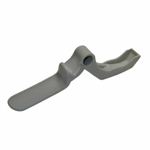
When maintaining or restoring your equipment, it’s crucial to identify which components may require replacement over time. Regular wear and tear, as well as exposure to various working conditions, often lead to the need for specific updates or swaps. Understanding the most common replacements and ensuring compatibility with other systems can significantly enhance the lifespan and performance of your tool.
Key Components for Replacement
- Motor brushes: Essential for ensuring proper electrical contact and maintaining efficient performance.
- Switches: Often the first point of failure due to constant use, switches are critical for controlling power and functionality.
- Wheels or gears: These parts can wear down from friction, affecting movement and operation.
- Air filters: Keeping the motor cool and free of dust, air filters are vital for prolonged use in dusty environments.
Ensuring Compatibility
- When replacing any part, ensure it matches the original model specifications to avoid operational issues.
- Verify the voltage and current ratings of electrical components, such as switches and motors, to ensure safety and efficiency.
- Use only compatible materials for moving parts to prevent damage from mismatched components.
- Check for manufacturer-approved replacements to avoid voiding warranties or compromising tool performance.
Exploring Diagrams for Troubleshooting Issues
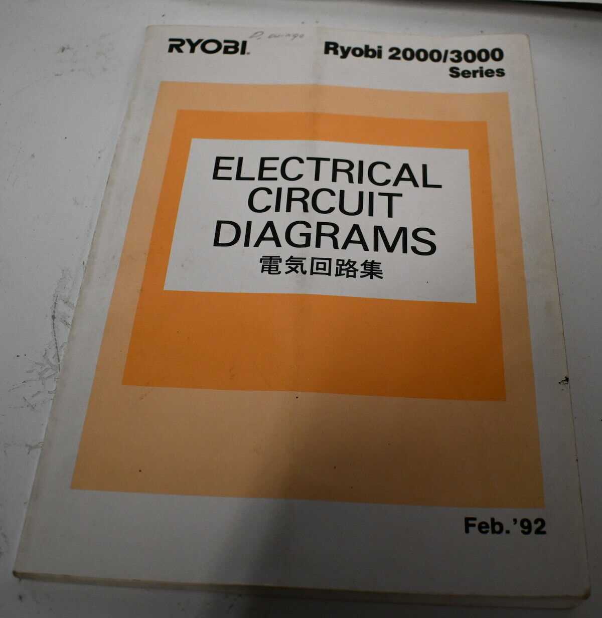
When faced with technical difficulties in your equipment, understanding its inner workings can greatly assist in diagnosing and fixing problems. Visual representations of the components and their connections offer valuable insight into how each part interacts. These tools can simplify the troubleshooting process by highlighting potential areas of concern and allowing you to pinpoint malfunctioning sections more easily.
Identifying Potential Faults
By closely examining these visual guides, you can quickly determine which parts are responsible for specific functions. This makes it easier to isolate faulty components and understand their role in the overall operation. A clear, organized illustration of the system will help you track down any discrepancies that may be causing performance issues.
Step-by-Step Troubleshooting

Using a visual reference allows for a more methodical approach to problem-solving. Instead of guessing or checking parts randomly, you can systematically verify the condition of each element in the system, ensuring nothing is overlooked. The following table outlines common sections to check and their related symptoms:
Component Possible Issue Suggested Action Motor No power or weak performance Check wiring connections and test voltage Switch Unresponsive or intermittent function Inspect contacts and replace if worn Battery Low charge or failure to hold charge Test with a multimeter and replace if necessary