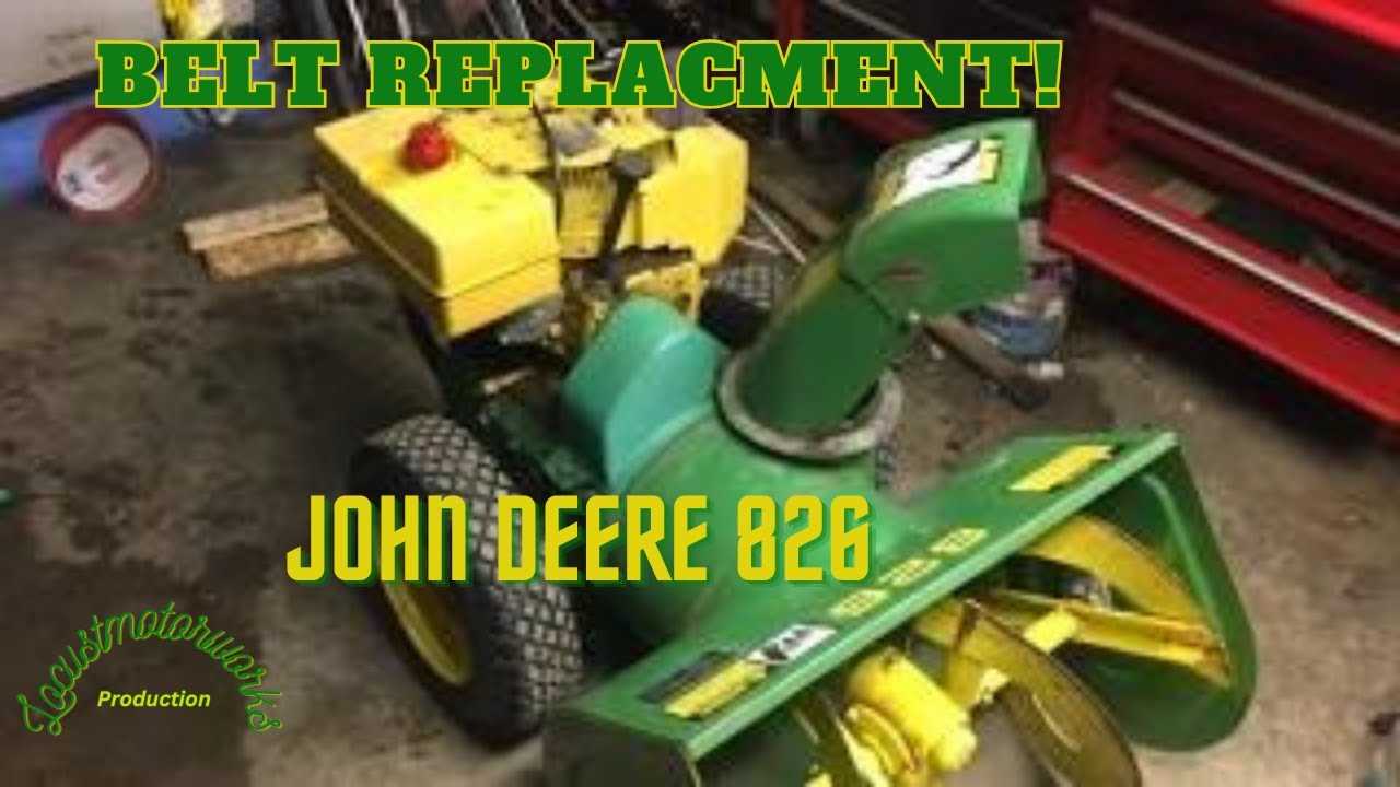
Understanding the structure and arrangement of key mechanical elements is crucial for maintaining efficient functionality. By knowing how each piece fits together, users can ensure their machine operates smoothly and without unnecessary breakdowns.
In this guide, we’ll explore the various components that make up a complex outdoor device, focusing on how these parts interconnect. Regular inspection and familiarity with their placement will help keep everything in top working condition.
Whether performing maintenance or troubleshooting, this overview will provide a solid foundation for identifying and addressing any issues that may arise over time.
John Deere 726E Parts Overview
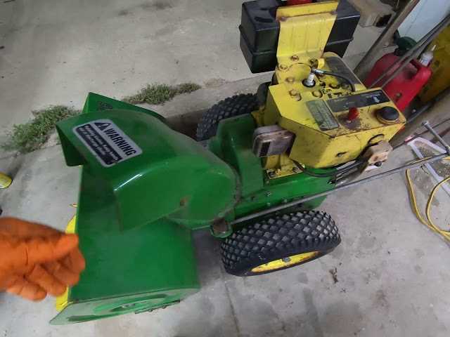
In this section, we will provide a detailed look into the components that make up this efficient machine. The following information will highlight the crucial elements that contribute to its overall performance, durability, and user experience. Each component is designed to work in harmony, ensuring the equipment runs smoothly during operation.
Key Components Breakdown
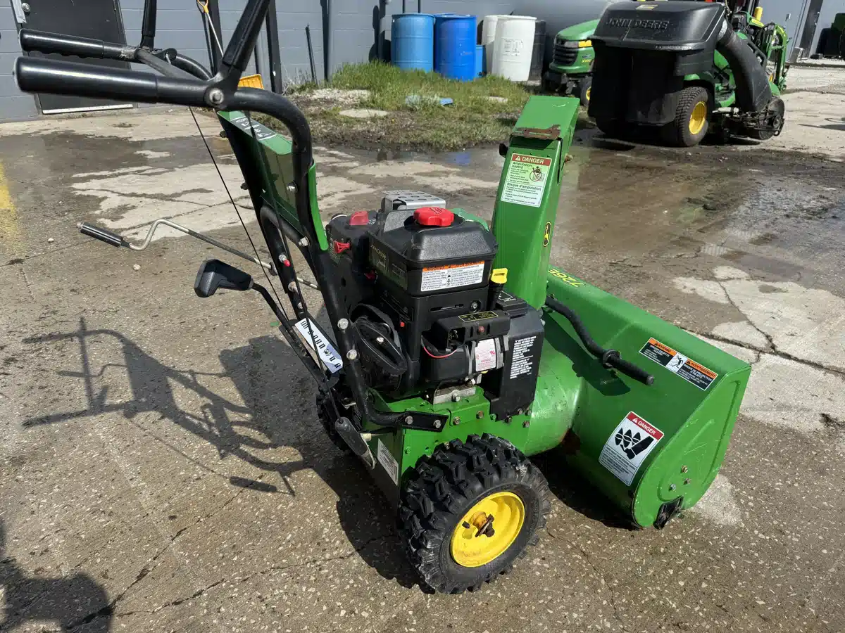
The unit consists of several important sections that are essential for its functionality. Below is a summary of the main components and their roles in ensuring the system operates effectively in different conditions.
| Component | Function | |||||||||||||||||||||||
|---|---|---|---|---|---|---|---|---|---|---|---|---|---|---|---|---|---|---|---|---|---|---|---|---|
| Auger Assembly | Responsible for cutting through and collecting material, feeding it into the chute. | |||||||||||||||||||||||
| Chute Control | Allows the operator to direct the expelled material accurately. | |||||||||||||||||||||||
| Drive System | Ensures forward and reverse movement, aiding in maneuverability. |
| Feature | Function | |||||||||||||||||||
|---|---|---|---|---|---|---|---|---|---|---|---|---|---|---|---|---|---|---|---|---|
Power Switch
Transmission and Drive SystemThe transmission and drive system play a crucial role in ensuring smooth and efficient movement of the equipment. This mechanism is responsible for transferring power from the engine to the wheels, enabling the machine to move forward or backward with ease. The system is designed to handle various terrains and operational conditions, making it a key component for reliable performance. Drive Mechanism: The drive mechanism is structured to offer optimal control over movement. It allows the operator to adjust speed according to different surfaces, ensuring consistent operation. Proper maintenance of the drive system enhances its durability and ensures long-term functionality. Transmission Functionality: The transmission ensures that the power generated is adequately distributed across the machine. With the correct transmission settings, the equipment can handle varying loads and perform efficiently under different conditions. Regular checks and adjustments of the transmission system will keep the machine running smoothly. Handle and Steering ElementsThe control components of a snow clearing machine play a crucial role in ensuring efficient operation and maneuverability. Understanding these elements helps users effectively manage their equipment while navigating through challenging conditions.
Familiarity with these elements can significantly enhance the overall experience, leading to improved performance and satisfaction during use. Chute Adjustment ComponentsThe effective operation of a snow clearing machine relies heavily on the precision of its discharge chute. Proper adjustment ensures optimal direction and distance of snow ejection, enhancing the overall efficiency of the equipment. Understanding the various elements involved in this mechanism is crucial for maintaining performance and functionality. Main Parts of the Adjustment MechanismThe primary components that facilitate the chute adjustment include levers, cables, and mounting brackets. Levers allow the operator to modify the chute’s angle with ease, while cables connect the levers to the chute itself, enabling smooth movement. Mounting brackets secure these parts in place, ensuring stability during operation. Wheels and Tracks StructureThe configuration of wheels and tracks plays a crucial role in the overall performance and stability of outdoor machinery designed for winter operations. This section delves into the design elements that contribute to optimal traction and maneuverability, ensuring efficient operation on various surfaces. Design Features
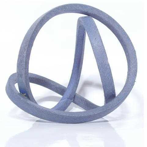
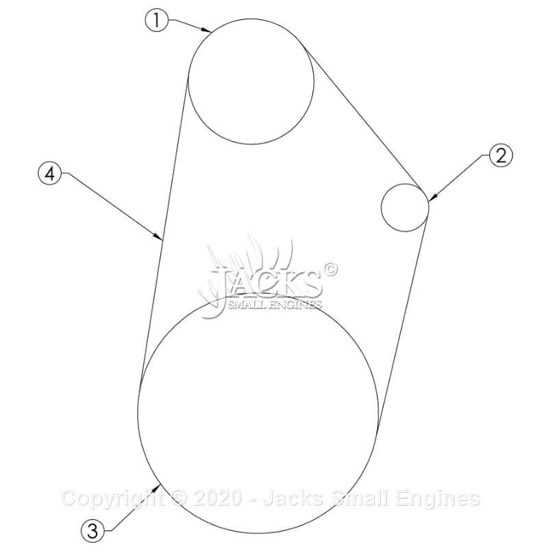
The wheels and tracks are engineered to enhance grip and control in challenging conditions. The tread patterns are meticulously crafted to facilitate effective displacement of snow while minimizing slippage. Additionally, the materials used in their construction are selected for durability and resilience, enabling them to withstand harsh weather conditions. Maintenance ConsiderationsRegular upkeep of the wheels and tracks is essential for maintaining peak performance. Inspections should focus on wear and tear, ensuring that the tread remains intact and free from obstructions. Proper maintenance practices not only extend the lifespan of these components but also ensure safety during operation. Belt and Pulley ConfigurationThe arrangement of belts and pulleys plays a crucial role in the effective operation of various machinery. Understanding this setup is essential for ensuring optimal performance and maintenance. Proper alignment and tensioning of these components directly impact the efficiency and longevity of the equipment. Key Components
In this system, several key elements work together to transmit power from the engine to the working parts. Each component must be regularly inspected to maintain functionality and prevent premature wear.
Maintenance TipsRegular maintenance of the belt and pulley system is vital for ensuring reliable operation. Routine checks should include inspecting for wear, adjusting tension, and ensuring proper alignment. By following these guidelines, users can enhance the lifespan and performance of their machinery. Maintenance Points and Lubrication Diagram
Proper upkeep of your equipment is essential for optimal performance and longevity. Regular maintenance ensures that all components function smoothly, preventing wear and tear. Understanding the lubrication needs of various parts is crucial in achieving this goal. Key areas that require attention include the drive mechanism, auger system, and any pivot points. Ensuring these elements are adequately lubricated will help in minimizing friction and extending the lifespan of the machinery. Refer to the accompanying illustration for specific locations and recommended lubricants to be used. It is advisable to check lubrication levels frequently, especially before and after use. This practice not only enhances efficiency but also safeguards against unexpected breakdowns. Adopting a routine maintenance schedule will significantly improve the reliability and performance of your equipment. Electrical System Parts IdentificationThis section provides an overview of the components that make up the electrical framework of the machine. Understanding these elements is crucial for effective maintenance and troubleshooting. Each component plays a vital role in the functionality and reliability of the overall system. Key Components OverviewIdentifying the main components is essential for anyone looking to service or enhance the electrical system. Below is a list of key elements typically found within the system:
Understanding Component FunctionsEach part within the electrical system serves a specific purpose, contributing to the overall efficiency of the machine. Familiarity with these components enables better decision-making during repairs and upgrades, ensuring that the system operates smoothly and effectively. |
