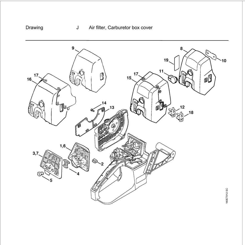
In the realm of maintaining complex machines, understanding how various elements interact and fit together is crucial. This guide provides detailed insights into the arrangement of critical components, helping users effectively navigate through the intricacies of assembly and repair.
Accurate identification of individual components can make all the difference when it comes to ensuring efficient functionality and longevity. With this resource, users can explore the precise positioning of each element, aiding in both troubleshooting and maintenance.
Whether you’re looking to fine-tune performance or repair specific mechanisms, having a clear visual reference of the assembly structure is essential. This guide serves as a reliable reference point, simplifying the process of understanding how each piece fits into the bigger picture.
Overview of the Stihl 028 Wood Boss
The device in question is a reliable and well-known tool for cutting tasks, favored for its balance between power and efficiency. It has earned a reputation for durability, making it a popular choice among both professionals and homeowners who work in demanding environments. Its robust construction allows it to handle various types of tasks with ease, from small jobs to more intensive projects.
Key features include a sturdy engine and well-designed cutting mechanism that ensure smooth performance. The equipment’s ergonomic design provides comfort during extended use, minimizing fatigue and enhancing productivity. Its versatility makes it suitable for a range of tasks, making it a valuable asset for anyone in need of a dependable cutting tool.
Main Components of the Chainsaw
A chainsaw is composed of several essential elements that work together to ensure efficient cutting performance. Understanding these components allows for better maintenance and use of the tool, contributing to its longevity and effectiveness.
Engine Unit
The power source of the chainsaw, the engine unit, generates the necessary force to drive the chain. It typically consists of a combustion engine or an electric motor, depending on the type of chainsaw. This section houses critical parts like the cylinder, piston, and crankshaft, all working in unison to produce mechanical energy.
Cutting Mechanism
The cutting mechanism is comprised of a guide bar and a cutting chain. The guide bar provides a stable path for the chain, which rotates rapidly to slice through materials. The sharp, evenly spaced teeth on the chain ensure a smooth and efficient cutting process, essential for tackling various tasks with precision.
Understanding the Engine Structure
The engine is a vital component of any mechanical system, designed to convert energy into motion. To fully grasp its functionality, it is essential to break down its core elements and understand how they work together to produce efficient performance.
Main Components
- Cylinder: The heart of the engine, where fuel combustion occurs, generating the necessary power to drive the system.
- Piston: A moving part inside the cylinder, responsible for transferring the force created during combustion to the crankshaft.
- Crankshaft: Converts the linear movement of the piston into rotational motio
Guide Bar and Chain Assembly Explained
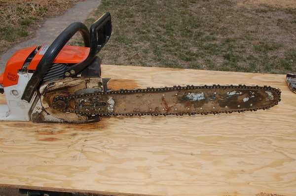
The guide bar and chain form a crucial element of any cutting tool, allowing for efficient and precise operation. Proper understanding of how these components interact ensures optimal performance and longevity. The assembly process is simple but requires attention to detail to avoid wear or damage.
Key Components Overview
The main parts involved in this assembly include the guide bar, the chain, and the tensioning mechanism. Each element plays a role in maintaining balance and control during cutting tasks. A well-maintained guide bar supports the chain, reducing friction and preventing binding.
Maintenance and Adjustment Tips
Regular inspection is vital to ensure the guide bar and chain remain aligned and properly tensioned. Misalignment or slack can lead to inefficient cutting or potential safety hazards. Ensure the tensioner is properly
Fuel and Oil System Diagram
The fuel and oil system is designed to ensure the smooth and efficient operation of the equipment, providing the necessary lubrication and fuel supply for optimal performance. Understanding the layout of these components can help in identifying potential issues and performing routine maintenance.
Fuel Delivery Components
The system that manages the delivery of fuel includes several key elements. The fuel tank stores the necessary liquid, while lines and filters ensure that it is directed to the engine cleanly and without obstruction. Each part is crucial for the steady flow of fuel during operation.
Oil Lubrication Path
Oil plays a vital role in reducing friction and cooling moving parts. The lubrication path ensures that all essential components receive the right amount of oil. From the reservoir
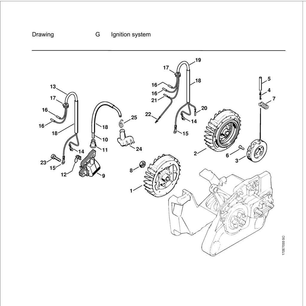
Ignition System Breakdown
The ignition mechanism is crucial for the proper functioning of any engine, ensuring that the combustion process occurs at the right moment. This section explores the components and functions of the ignition assembly, highlighting its significance in optimizing performance and efficiency.
Key Components
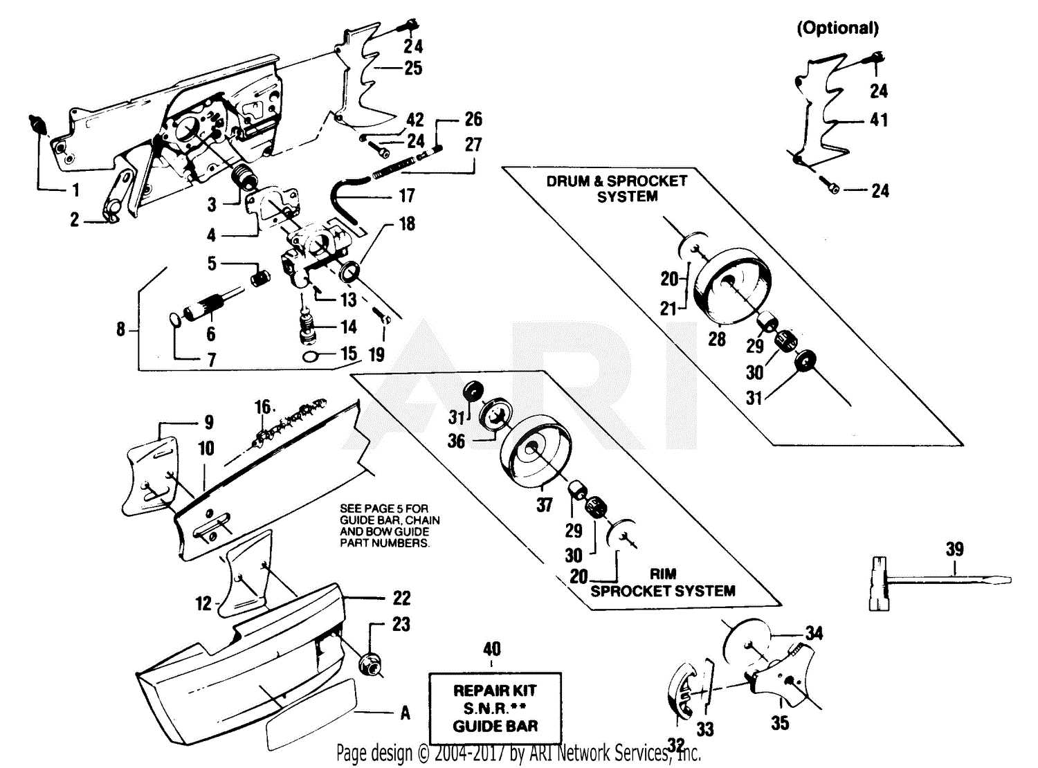
The ignition assembly consists of several essential elements that work in harmony. Each part plays a specific role in generating and delivering the spark needed for combustion. Understanding these components helps in diagnosing issues and maintaining the system effectively.
Component Description Ignition Coil Transforms low voltage from the battery into a high voltage needed to create a spark. Spark Plug Delivers the electrical spark to ignite the fuel-air mixture in the combustion chamber. Flywheel Magnet Generates a magnetic field that induces voltage in the ignition coil as it rotates. Ignition Module Controls the timing of the spark and ensures optimal performance of the ignition system. Functionality Overview
The ignition system operates by creating a spark that ignites the fuel mixture within the engine’s cylinders. This process is synchronized with the engine’s cycle to ensure that combustion occurs efficiently. Regular inspection and maintenance of these components are vital to prevent ignition failures and maintain optimal engine performance.
Clutch Mechanism and Operation
The clutch mechanism plays a crucial role in the functionality of power equipment, allowing for the controlled transfer of power from the engine to the working components. This system ensures that the tool operates efficiently, engaging and disengaging based on the user’s input and the operational requirements.
In general, the clutch operates through a combination of springs and centrifugal force. When the engine reaches a certain speed, the centrifugal force overcomes the tension of the springs, causing the clutch shoes to expand and engage with the drum. This engagement allows power to flow from the engine to the attachment, facilitating effective operation.
Component Function Clutch Shoes Expand under centrifugal force to engage with the drum. Drum Transfers power from the clutch shoes to the drive shaft. Springs Maintain tension to keep the clutch disengaged at lower speeds. Bearings Support the rotating components, ensuring smooth operation. Understanding the mechanics of the clutch is essential for proper maintenance and troubleshooting. Regular inspections and adjustments can prolong the life of the system and enhance the overall performance of the equipment.
Air Filtration and Cooling System
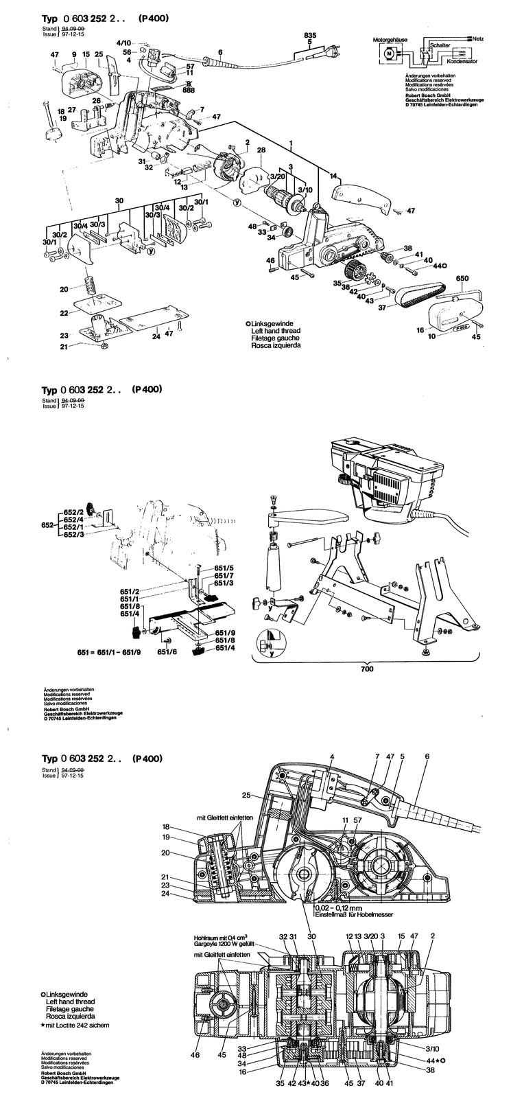
The efficiency of a motorized device relies heavily on its ability to maintain optimal operating conditions. An essential aspect of this is the mechanism responsible for filtering airborne impurities and regulating temperature. A well-designed filtration and cooling setup ensures that the internal components remain free from debris while preventing overheating during prolonged use.
Filtration Components play a crucial role in protecting the engine. These elements trap dust and particles, allowing clean air to enter the combustion chamber. Regular maintenance of these filters is vital to ensure maximum airflow and performance. Clogged or damaged filters can lead to reduced efficiency and potential engine wear.
Cooling Systems work in tandem with filtration to dissipate excess heat generated during operation. Various methods, including air circulation and cooling fins, help maintain a suitable temperature range, enhancing overall reliability. Adequate cooling is vital to prevent overheating, which can lead to mechanical failure and decreased performance over time.
Handle and Trigger Components
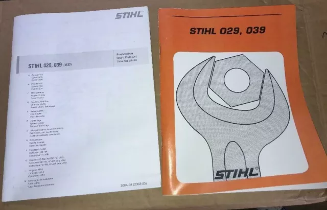
The handle and trigger mechanisms are vital elements in power tools, enabling effective control and maneuverability. These components ensure that the operator can maintain a secure grip while easily accessing the trigger for operation. Proper functioning of these parts is essential for both safety and performance during use.
Key elements of the handle and trigger system include the handle grip, trigger switch, and safety lock. Each of these parts plays a crucial role in the overall functionality of the equipment. Below is a summary of these components:
Component Description Handle Grip The section designed for the operator to hold securely, providing comfort and control during operation. Trigger Switch A mechanism that activates the power tool when pressed, allowing for easy operation. Safety Lock A feature that prevents accidental activation of the trigger, enhancing user safety. Carburetor Parts and Adjustments
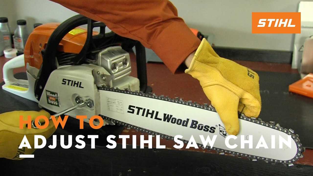
The carburetor is a critical component responsible for mixing air and fuel in the appropriate ratio for optimal engine performance. Proper maintenance and adjustment of this mechanism ensure efficient operation and longevity of the equipment.
Key Components of the Carburetor
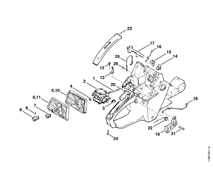
- Float Chamber: Regulates the fuel level, ensuring a steady supply to the mixing area.
- Needle Valve: Controls fuel flow into the float chamber based on demand.
- Jet: Delivers fuel into the air stream, influencing the air-fuel mixture.
- Throttle Plate: Regulates air intake, affecting engine speed and power output.
- Adjusting Screws: Allow fine-tuning of the air-fuel mixture for varying operating conditions.
Adjustment Techniques
- Start by ensuring the engine is at operating temperature.
- Locate the adjusting screws for both idle and high-speed settings.
- Turn the idle screw clockwise to increase RPM or counterclockwise to decrease RPM.
- Adjust the high-speed screw while running the engine at full throttle until the desired performance is achieved.
- Test the equipment under load to ensure proper adjustments have been made.
Regular inspection and adjustment of these components can significantly enhance engine efficiency and responsiveness.
Troubleshooting Common Issues
When working with outdoor power equipment, encountering problems is not uncommon. Identifying and resolving these issues promptly can significantly enhance the performance and longevity of your machine. Below are some common challenges users face and their potential solutions.
- Engine Won’t Start:
- Check the fuel level and ensure it is fresh and uncontaminated.
- Inspect the spark plug for damage or wear; replace if necessary.
- Examine the air filter and clean or replace it if clogged.
- Power Loss:
- Look for obstructions in the exhaust system that might be restricting airflow.
- Ensure that the fuel mixture is correct and not too diluted.
- Verify that the ignition system is functioning properly.
- Excessive Vibration:
- Check for loose or damaged components that may be causing instability.
- Ensure that the cutting attachment is securely mounted and balanced.
- Inspect for wear on bearings or bushings, and replace if necessary.
- Overheating:
- Examine the cooling fins for dirt and debris, and clean them thoroughly.
- Ensure that the fuel system is free from clogs that could affect performance.
- Monitor the operating conditions to avoid excessive strain on the engine.
By systematically addressing these common issues, you can maintain optimal operation and extend the life of your equipment. Regular maintenance and attentive observation are key to preventing most problems.