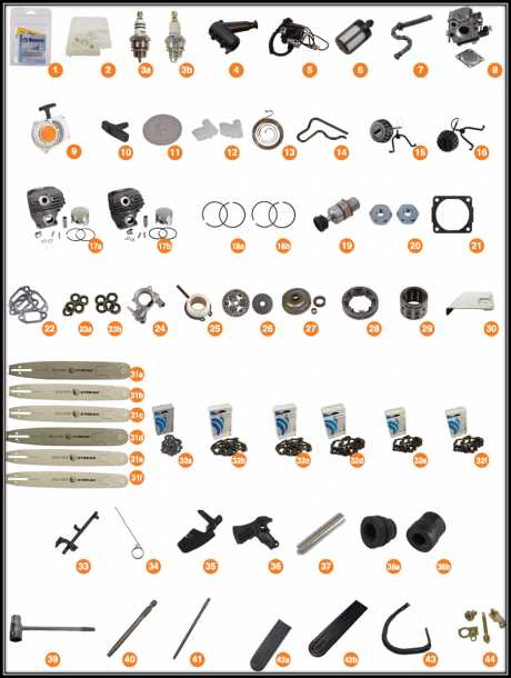
When it comes to maintaining outdoor equipment, one of the key aspects to consider is understanding how each component interacts within the overall structure. This knowledge allows for efficient repairs and long-term upkeep. Whether you are dealing with a small handheld device or a larger mechanical unit, a clear visualization of how various sections connect can make all the difference.
Exploring the layout of mechanical devices not only helps with assembly and disassembly but also assists in diagnosing performance issues. For hobbyists and professionals alike, having a detailed view of key elements can simplify tasks and reduce downtime. This guide focuses on the layout of a well-known tool, providing a breakdown of its internal structure and offering tips for identifying common challenges during repair and maintenance.
Overview of the Stihl 026 Chainsaw Components
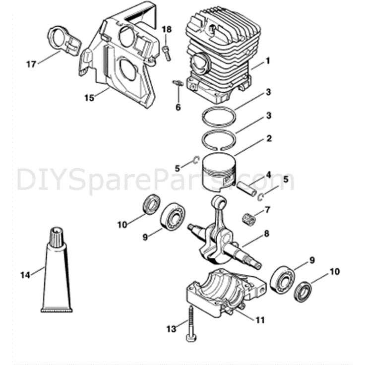
In this section, we will explore the essential elements that come together to form a reliable and efficient cutting tool. Each component plays a critical role in ensuring optimal performance and durability, contributing to the smooth operation of the device under various conditions. By understanding how these parts interact, users can better maintain and troubleshoot the machine, ensuring long-lasting functionality.
The tool is composed of several key areas, including the power source, cutting mechanism, and safety features. These areas are carefully designed to work together, providing both precision and power during operation. Proper maintenance and knowledge of these systems are crucial for both novice and experienced operators.
Additionally, special attention is given to the protective mechanisms built into the device. These not only extend the lifespan of the tool but also enhance user safety, allowing for a more controlled and secure experience when handling the equipment.
Engine Assembly Breakdown
The core of any motorized tool is the power unit, consisting of various interconnected components working together to ensure efficient performance. Understanding the internal layout is key for maintenance and repairs, allowing users to troubleshoot issues or replace worn-out elements with precision.
Main Components Overview
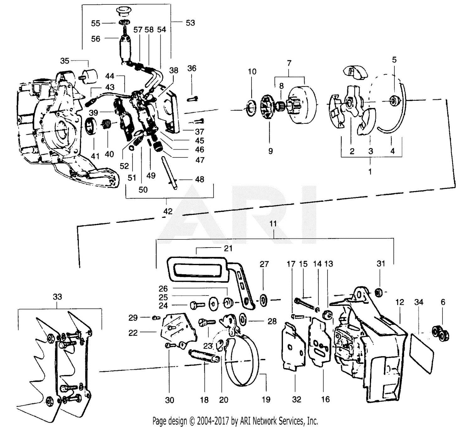
- Piston and cylinder
- Crankshaft assembly
- Carburetor
- Ignition system
- Cooling mechanism
Steps for Disassembly
- Remove the outer casing to access internal parts.
- Detach the carburetor, ensuring no fuel leakage.
- Loosen the bolts securing the cylinder to access the piston.
- Unbolt the crankshaft housing and remove the assembly carefully.
- Inspect all elements for wear or damage.
Reassembling requires attention to detail, ensuring each part fits seamlessly to restore the tool
Starter Mechanism Function and Maintenance
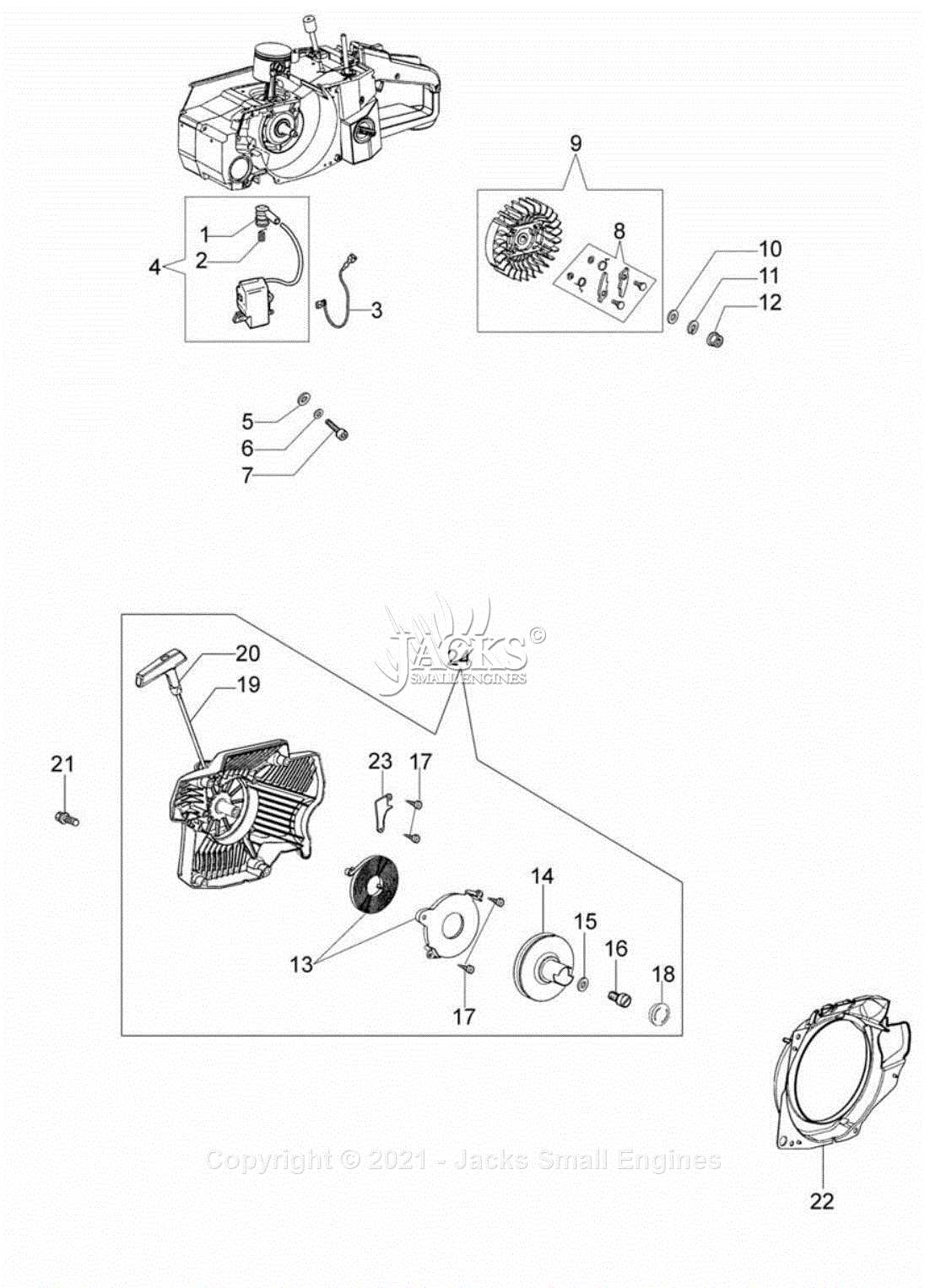
The starter mechanism plays a critical role in enabling smooth and efficient operation of various motorized tools. Its primary function is to initiate the engine’s cycle by manually generating the initial rotation needed for ignition. Regular upkeep of this system ensures reliable starting performance and prevents common issues like misfires or delayed responses. By understanding the components and their roles, users can maintain optimal performance and prolong the life of the mechanism.
Key Components of the Starter Mechanism
At the heart of this system is the cord and recoil spring assembly. The cord, when pulled, engages the spring, causing tension that releases energy to turn the engine. Other important elements include the pulley, ratchet mechanism, and housing, each contributing to the smooth functioning of the starting process. Keeping these parts in good condition is essential for maintaining proper operation.
Maintenance Tips
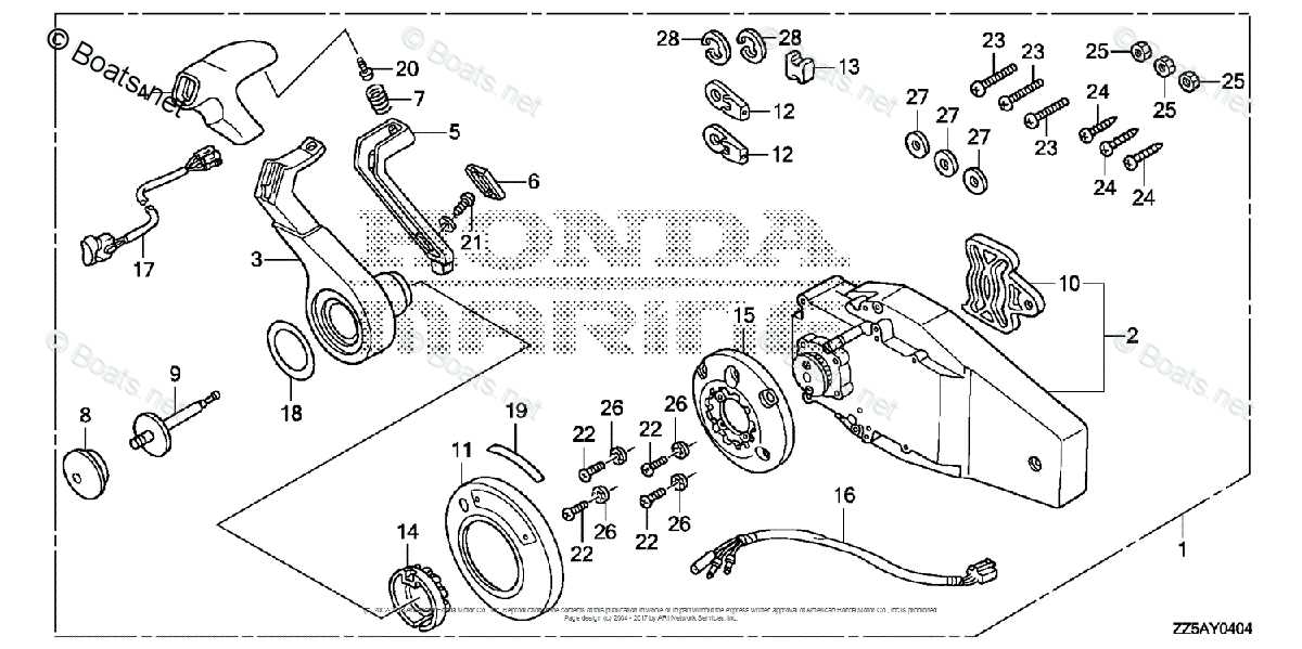
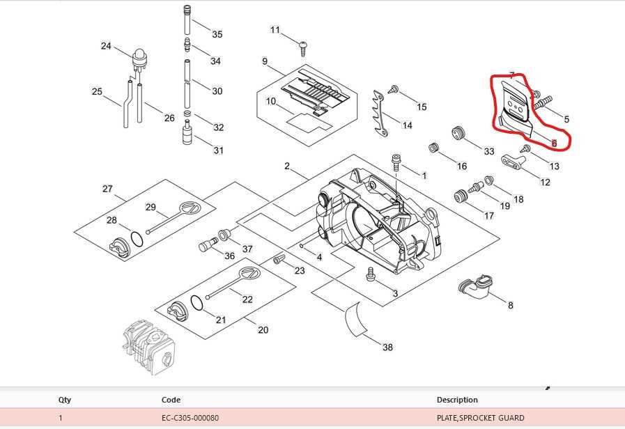
To ensure the longevity of the starter mechanism, periodic cleaning and inspection are recommended. Dirt or debris can accumulate inside the housing, leading to obstructions or wear on moving parts.
Fuel System and Carburetor Details
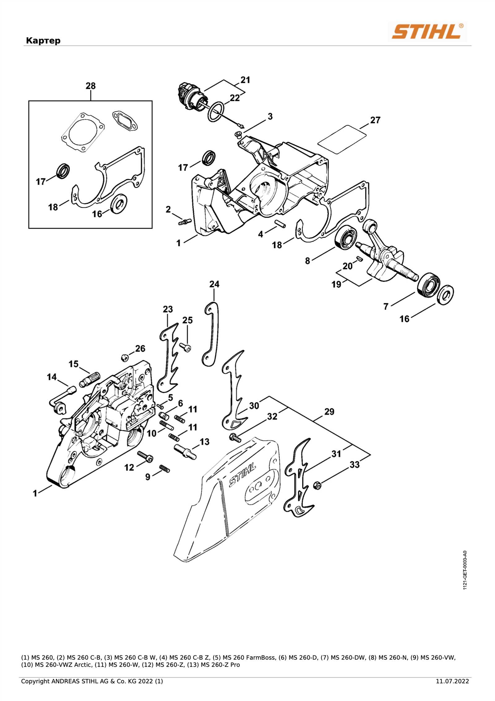
The functionality of the engine relies heavily on a well-maintained fuel system, which ensures consistent performance by delivering the proper fuel-to-air mixture. The system includes several interconnected components designed to optimize fuel flow and combustion efficiency.
At the heart of this system lies the carburetor, a precision device responsible for mixing air and fuel in the correct proportions before they enter the combustion chamber. Proper tuning of this component is essential for smooth operation and preventing issues such as poor acceleration or inconsistent idling. Keeping it clean and well-adjusted can significantly extend the engine’s lifespan and performance.
Additionally, maintaining the cleanliness of the fuel filter and ensuring the correct fuel lines are in place will help avoid blockages and other potential issues that could disrupt fuel delivery. Regular inspection and proper maintenance are key factors in keeping this system running efficiently.
Ignition Coil and Spark Plug Placement
The correct arrangement of key components in the ignition system is essential for smooth engine performance. Understanding the position and interaction between these elements can significantly improve the efficiency and reliability of the motor, particularly during start-up and sustained operation.
Component Alignment and Positioning
In most small engines, the ignition coil is located near the flywheel, working closely with the spark plug to generate the necessary charge. The precise placement ensures a seamless transmission of energy, which is critical for igniting the fuel-air mixture. Aligning these components accurately is vital for reducing misfires and ensuring reliable power delivery.
Ensuring Proper Connection
To maintain peak functionality, the connection between the coil and the plug must remain secure. Any loose or faulty connections can lead to weak sparks or even engine failure. Periodic inspection of the wiring and component placement helps in maintaining consistent performance and avoiding sudden operational issues.
Air Filter and Intake System Layout
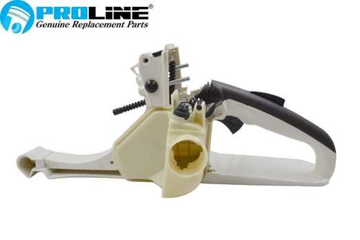
The efficiency of a cutting tool relies significantly on its air filtration and intake mechanisms. These components are vital for ensuring a steady supply of clean air to the engine, facilitating optimal combustion. A well-designed intake system not only enhances performance but also prolongs the lifespan of the engine by minimizing contaminants that could cause wear and tear.
Components of the Air Intake System
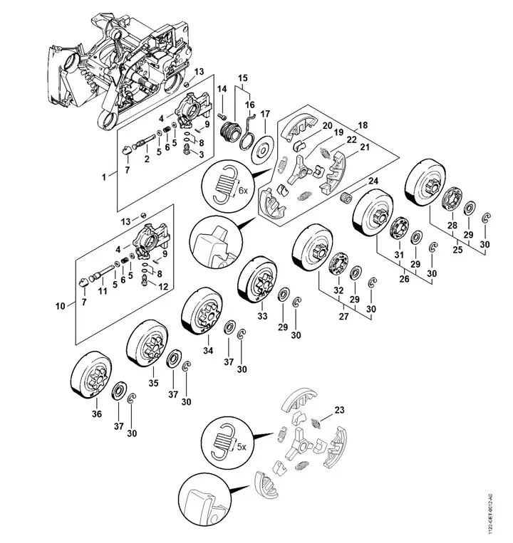
The air intake system typically consists of several key elements. The primary component is the air filter, which captures dust and debris before they enter the engine. Alongside the filter, intake tubes and ports guide the airflow, ensuring that the engine receives an adequate amount of air under various operating conditions. Proper maintenance of these parts is crucial for preventing airflow restrictions and maintaining overall efficiency.
Maintenance Tips
Guide Bar and Chain Tensioning
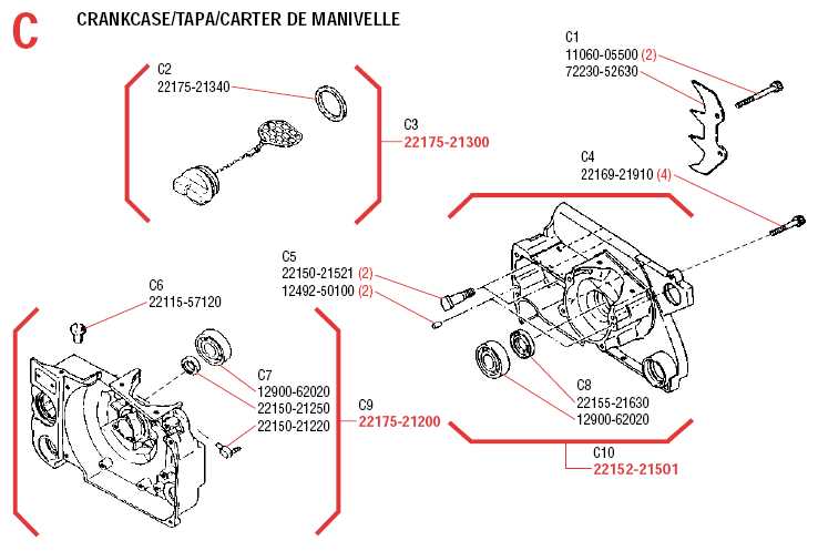
Maintaining optimal tension in the guiding component and the cutting loop is essential for achieving efficient operation and prolonging the lifespan of your equipment. Properly adjusted tension prevents excessive wear and tear, reduces the risk of damage, and enhances cutting performance. Regular inspection and adjustment of these components can significantly improve your experience and ensure safety during usage.
To achieve the correct tension, first, ensure that the cutting loop is properly seated on the guiding component. Use the tensioning mechanism to adjust the tightness, making sure the loop has a slight amount of play. A properly tensioned loop should not sag excessively but should also allow for smooth movement. If the cutting loop feels too tight or shows signs of wear, it may need replacement or further adjustment.
Remember to check the tension frequently, especially after extended use. Factors such as heat and friction can affect the tightness of the cutting loop, leading to potential operational issues. By following these guidelines, you can maintain optimal performance and ensure safe operation.
Clutch System and Sprocket Overview
The clutch mechanism and sprocket assembly play crucial roles in the functionality of high-performance cutting tools. These components work in harmony to ensure that the tool operates efficiently, allowing for optimal power transfer and effective cutting performance. Understanding their design and operation is essential for proper maintenance and troubleshooting.
Clutch Mechanism
The clutch is responsible for engaging and disengaging the drive system based on the user’s input and the load on the cutting attachment. When the user activates the throttle, the clutch engages, transferring engine power to the drive system. A well-functioning clutch ensures smooth operation and reduces wear on components, which is vital for maintaining longevity and efficiency.
Sprocket Assembly
The sprocket is a key element that connects the drive system to the cutting attachment. It is designed to transmit rotational force and accommodate different chain configurations. Regular inspection of the sprocket is important, as wear can lead to reduced performance and potential damage to the entire drive system. Ensuring proper alignment and lubrication will enhance the longevity of this essential component.
Exhaust Muffler Positioning and Removal
Proper placement and disassembly of the exhaust silencer are crucial for optimal performance and maintenance. This section will guide you through the necessary steps to effectively locate and detach the component, ensuring smooth operation and reducing the risk of damage to the engine.
To begin the process, it is essential to understand the positioning of the exhaust system. The silencer plays a key role in directing fumes away from the engine and minimizing noise levels. Ensuring its correct alignment is vital for both efficiency and safety during operation.
When it comes time to remove the exhaust muffler, follow these steps:
| Step | Description |
|---|---|
| 1 | Ensure the unit is completely cool and disconnected from any power source. |
| 2 | Locate the screws or bolts securing the silencer to the engine casing. |
| 3 | Using the appropriate tools, carefully unscrew or unbolt the silencer. |
| 4 | Gently pull the silencer away from the engine, taking care not to damage any gaskets or seals. |
| 5 | Inspect the silencer and surrounding components for wear or damage before reassembly. |
Following these instructions will help ensure that the exhaust muffler is properly positioned and easily removed when necessary, contributing to the overall functionality and longevity of the machine.
Oil Pump and Lubrication Path
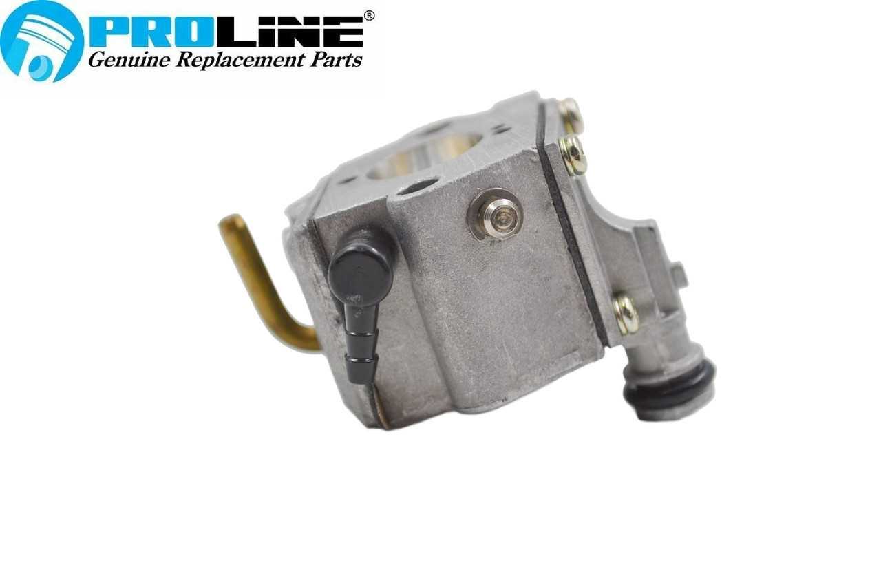
The efficiency of any cutting tool heavily relies on its ability to maintain proper lubrication. This section explores the mechanisms involved in delivering oil to critical components, ensuring smooth operation and extending the lifespan of the equipment.
At the core of this lubrication system is the oil pump, which plays a vital role in transporting lubricant from the reservoir to various moving parts. The following points highlight the key features and functions of this mechanism:
- Oil Pump Functionality: The pump draws lubricant from the tank and delivers it under pressure to ensure adequate coverage of the cutting mechanism.
- Lubrication Path: The path taken by the oil is designed to reach essential areas, such as the chain and bar, minimizing friction and wear.
- Adjustable Flow Rate: Many systems allow the user to adjust the oil flow, enabling customization based on the working conditions and material being cut.
- Self-Priming Capability: This feature ensures that the system can quickly establish oil flow without manual intervention, reducing downtime.
Understanding the oil pump’s operation and lubrication path is crucial for maintaining optimal performance and preventing overheating. Regular maintenance of the lubrication system ensures that the tool remains efficient and reliable during use.
Handle and Anti-Vibration System Structure
The design of the grip and vibration dampening system is crucial for ensuring user comfort and operational efficiency. This structure plays a significant role in reducing fatigue during prolonged use, allowing for better control and stability when handling the equipment.
Key components of the grip and anti-vibration system include:
- Handle: Ergonomically designed to fit comfortably in the user’s hand, minimizing strain.
- Dampeners: Special materials or mechanisms that absorb vibrations generated during operation.
- Mounting System: Connects the handle to the main body, contributing to stability and reducing the transmission of vibrations.
The integration of these elements helps to enhance the overall performance of the tool. Effective vibration reduction not only improves comfort but also prolongs the lifespan of both the equipment and its components.
Considerations in the design of the grip and anti-vibration features include:
- Material selection for durability and shock absorption.
- Geometry of the handle for optimal grip and control.
- Positioning of the dampeners to maximize effectiveness.
Overall, a well-engineered handle and vibration mitigation system is essential for achieving operational excellence and ensuring the safety of the user.
Chain Brake Mechanism Explained
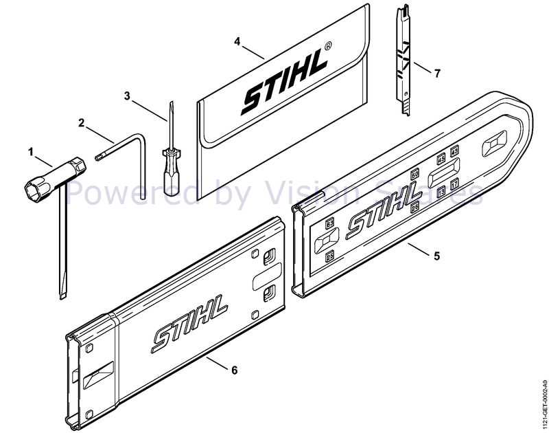
The chain brake mechanism is a vital safety feature in cutting tools, designed to stop the rotation of the chain swiftly in emergency situations. This functionality plays a crucial role in protecting the user from potential injuries during operation. Understanding how this system works is essential for effective maintenance and safe usage.
How It Works
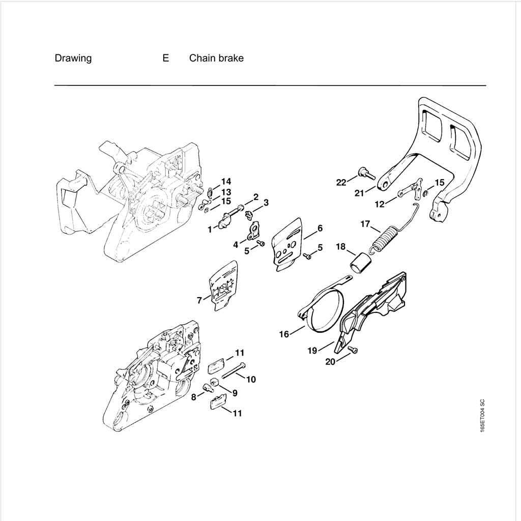
The chain brake operates through a simple yet effective design. When activated, it engages a brake band that grips the chain, halting its movement almost instantaneously. The mechanism is typically triggered by:
- A sudden jolt or kickback from the tool
- Manual activation by the user
- Automatic engagement due to inertia in specific models
Importance of Maintenance
Regular inspection and maintenance of the chain brake system are essential for optimal performance and safety. Here are key maintenance tips:
- Check for wear on the brake band regularly.
- Ensure the activation lever functions smoothly.
- Clean any debris that might hinder the mechanism’s operation.
By keeping the chain brake in proper working condition, users can significantly reduce the risk of accidents and ensure a safer working environment.
Replacement Parts and Compatibility Tips
When it comes to maintaining your outdoor power tool, understanding the components and ensuring the right replacements are crucial for optimal performance. Using compatible components not only enhances the efficiency of your equipment but also prolongs its lifespan. This section provides insights into selecting suitable substitutes and verifying compatibility.
Choosing the Right Substitutes
When searching for alternatives, always consider quality over cost. Opt for components from reputable manufacturers that meet or exceed the specifications of the original items. Reading reviews and checking for certifications can guide you in making informed choices that ensure your equipment remains reliable.
Verifying Compatibility
Before purchasing any replacements, double-check the specifications of your equipment. Cross-reference model numbers and consult manufacturer guidelines to ensure proper fitment. Many online resources and communities can provide helpful insights into compatibility, making it easier to find the right components for your specific model.