Understanding the structure and arrangement of various elements in a versatile tool can greatly enhance its performance and durability. This section will guide you through the internal and external configurations, helping you familiarize yourself with the essential mechanisms that make the equipment operate smoothly. Knowing where each component is located is key to both efficient maintenance and effective use.
Whether you’re performing routine upkeep or more advanced repairs, being able to identify each element of the equipment’s design is crucial. This guide will outline the key aspects of the assembly, ensuring that users are well-equipped to handle tasks related to service or replacement. A clear understanding of the setup can save time and extend the tool’s lifespan, contributing to overall reliability and user satisfaction.
Stihl KM 85 Parts Diagram Overview
The following section provides a comprehensive guide to the internal components and how they are structured within this versatile tool. It offers insight into the essential elements, allowing for a better understanding of how each piece interacts within the system. This knowledge can assist with both maintenance and repairs.
- Engine system configuration and layout
- Transmission mechanism and key features
- Handles and control elements for ergonomic use
- Protective coverings and shields
- Accessory attachment points and connections
Each section mentioned offers a glimpse into the tool’s design, ensuring that users can address potential issues or explore upgrade possibilities. Whether for maintenance or improvement, this overview supports efficient use and extended functionality.
Key Components of the Stihl KM 85
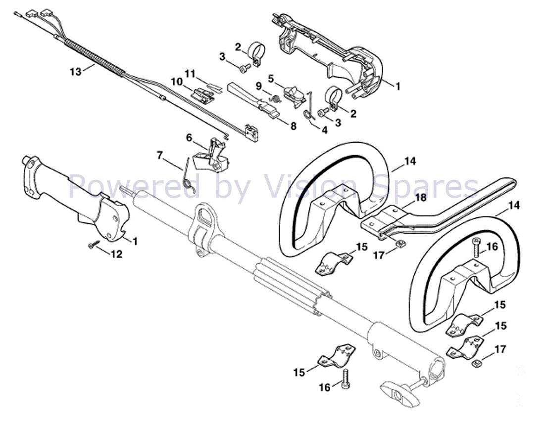
The following section outlines the most important elements that contribute to the effective performance of this versatile tool. These components ensure reliability, power, and adaptability, making it suitable for a wide range of tasks.
- Engine Unit: The heart of the machine, providing the necessary power for various attachments and operations.
- Control Handle: Designed for easy operation, allowing the user to control speed and direction efficiently.
- Coupling Mechanism: This component ensures quick and secure attachment of various extensions, making it highly adaptable.
- Protective Housing: A sturdy casing that shields the internal mechanisms, ensuring durability and safety during operation.
- Fuel Tank: A container designed to store and deliver fuel efficiently, optimizing performance
Understanding the Engine Assembly
The engine assembly is a crucial component that powers the entire system. It converts fuel into mechanical energy, enabling efficient operation. A clear understanding of how its various elements work together can help maintain optimal performance and ensure longevity.
Core Components
Within the engine assembly, several essential components interact to produce energy. The cylinder houses the piston, which moves up and down, creating the necessary pressure to ignite fuel. The crankshaft transforms this motion into rotational force, which is then used to drive other parts of the machine.
Functionality and Maintenance
To maintain the engine in top condition, regular inspection of the piston, crankshaft, and spark plug is essential. These parts must be well-lubricated and free from damage to avoid performance issues. Keeping the fuel lines clean and replacing filters at recommended intervals also helps to sustain efficient operation.
Throttle System and Its Functionality
The throttle mechanism plays a crucial role in controlling the engine’s power output. It allows the user to manage the engine’s speed and efficiency by adjusting the air and fuel mixture. Understanding how this system operates helps maintain smooth operation and prevent potential issues during use.
The throttle setup consists of several components working together to regulate engine speed. Each part is designed to ensure proper functionality, contributing to a smooth user experience.
- The throttle lever is responsible for controlling the engine’s speed by adjusting the airflow to the combustion chamber.
- The cable transmits the lever’s movement to the engine, ensuring accurate adjustments.
- A return spring ensures that the lever returns to its original position when released, preventing over-acceleration.
- The carburetor adjusts the mixture of air and fuel according to the throttle’s position.
Regular inspection and maintenance of the throttle system are essential to ensure that all components are functioning correctly. By keeping these parts in good condition
Air Filter Housing and Maintenance
The air filter system is essential for maintaining the longevity and efficiency of your equipment. Proper care of this component ensures that the internal mechanisms are protected from dust, debris, and other harmful particles that may enter the engine during operation.
Regular Inspection
Regularly inspecting the air filter housing helps detect any buildup of dirt or signs of wear. This inspection should be part of your routine maintenance to guarantee optimal performance and reduce the risk of engine damage. Pay attention to any cracks or loose fittings around the housing, as these can compromise the sealing and allow contaminants to enter.
Cleaning and Replacement
To keep the air intake system functioning properly, it’s important to clean or replace the filter periodically. Cleaning involves removing the filter, shaking off dirt, or using compressed air to clear any blockages. If the filter is heavily clogged or damaged, it should be replaced to maintain proper airflow and prevent overheating or decreased performance. Always ensure that the housing is
Fuel System Layout and Parts
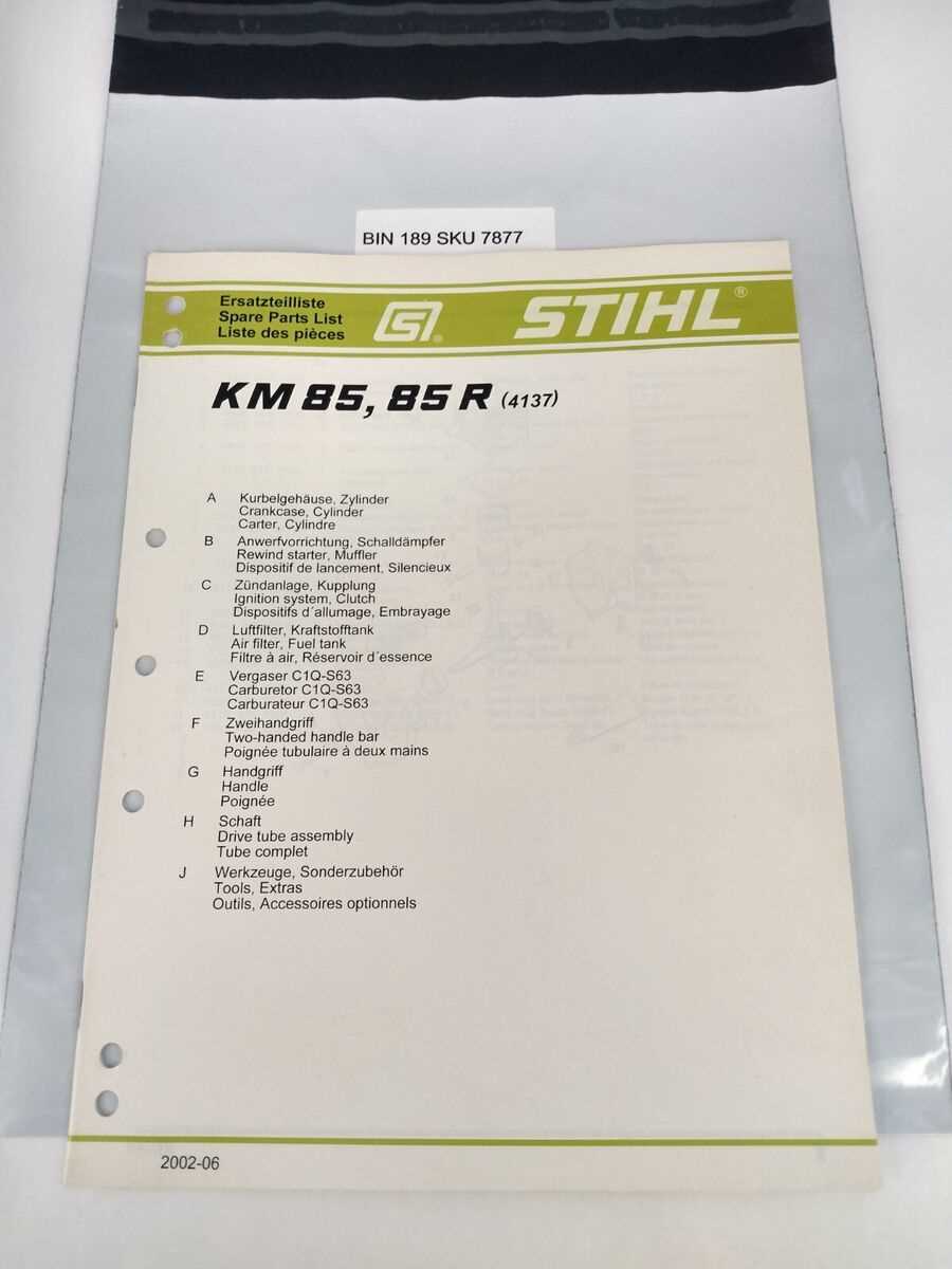
The fuel system of a multi-functional engine is critical for its operation, providing the necessary fuel to power the machine efficiently. Understanding its configuration and components is essential for maintenance and troubleshooting.
Key Components
- Fuel Tank: Stores the fuel required for operation.
- Fuel Filter: Removes impurities from the fuel to ensure clean delivery.
- Fuel Line: Transports fuel from the tank to the engine.
- Carburetor: Mixes air and fuel for combustion.
- Fuel Pump: Delivers fuel from the tank to the carburetor.
Fuel Flow Process
- Fuel is drawn from the tank by the fuel pump.
- The fuel filter cleans the fuel before it reaches the engine.
- The carburetor blends the fuel with air for optimal combustion.
- Mixture enters the combustion chamber, powering the engine.
Handlebar Assembly and Controls
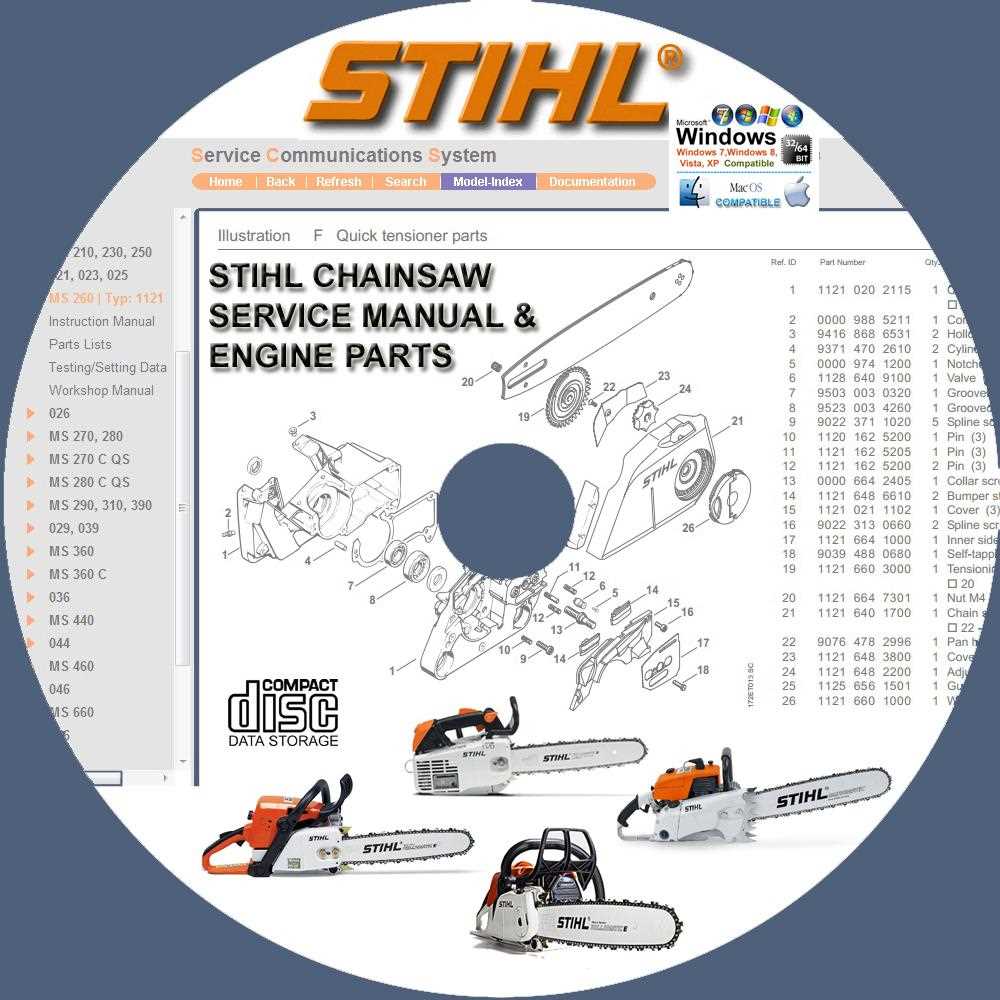
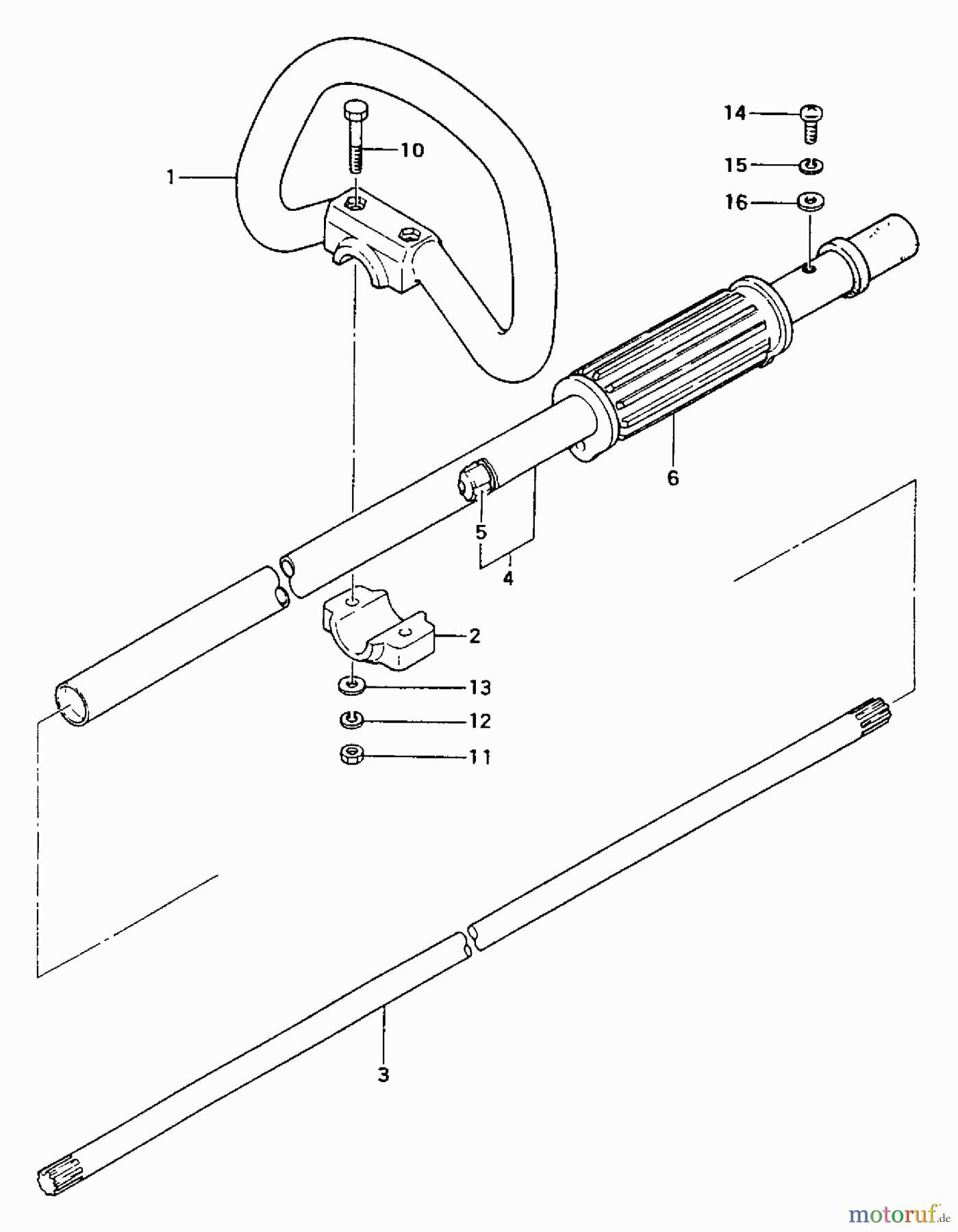
The handlebar assembly plays a crucial role in ensuring effective control and maneuverability of the equipment. It serves as the primary interface for the operator, allowing for comfortable handling while providing access to essential controls for operation. Understanding its components and their functions is vital for optimal performance and safety.
Components of the Handlebar Assembly
The assembly typically consists of the handlebar itself, grips, control switches, and safety features. The handlebar is designed to offer a secure grip, enabling users to navigate various terrains. Grips are often made from non-slip materials, enhancing comfort during extended use. Control switches are strategically positioned for easy access, allowing the operator to manage functions such as throttle and power without shifting their hands from the handle.
Safety Features
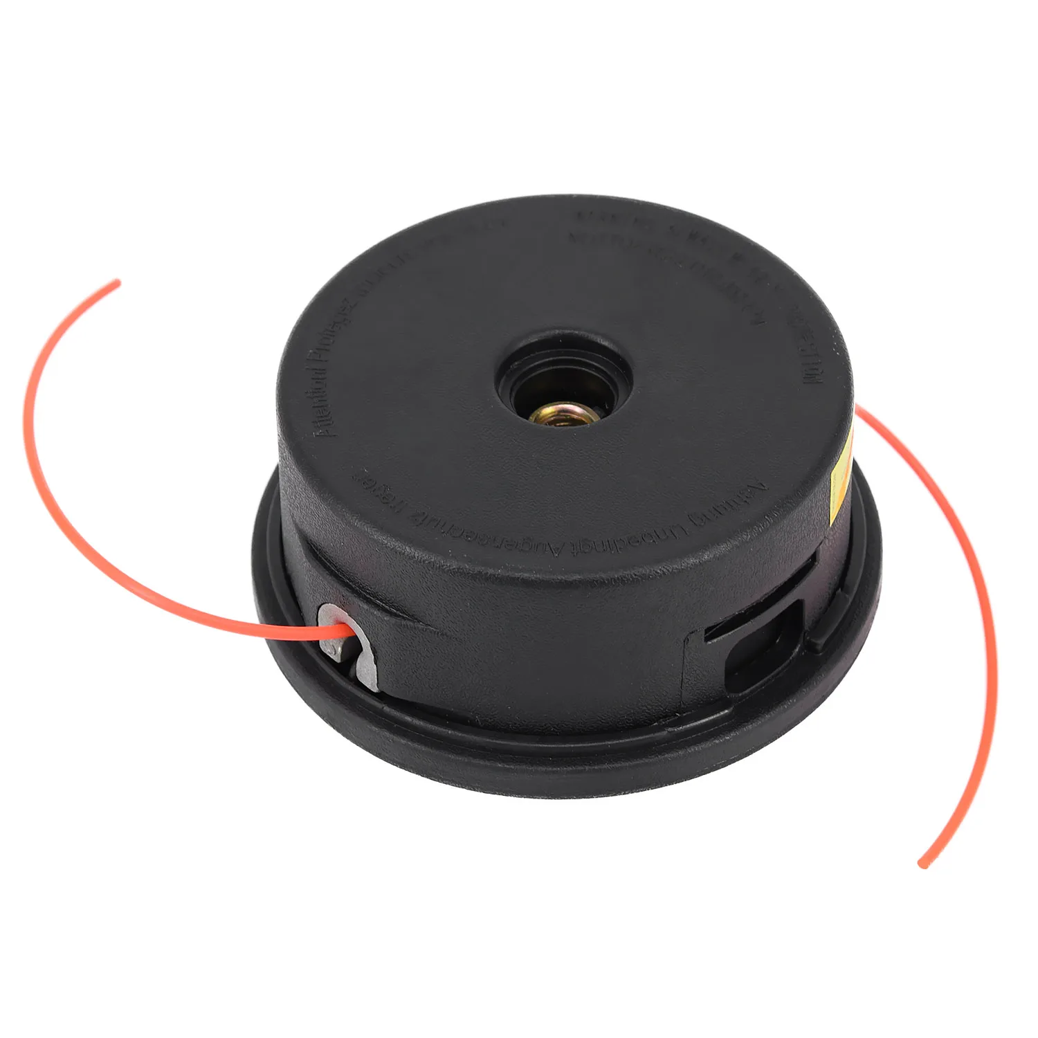
Incorporating safety features within the handlebar assembly is paramount. These may include emergency shut-off switches and ergonomic designs that reduce the risk of strain. Proper adjustment and maintenance of the handlebar ensure that all controls are within reach, contributing to a safer and more efficient operation.
Clutch Mechanism and Operation
The clutch mechanism is a vital component that facilitates the efficient transfer of power from the engine to the working tools. Its primary function is to engage and disengage the drive system, allowing the operator to control the tool’s operation seamlessly. Understanding how this mechanism works is crucial for optimal performance and maintenance.
At the heart of the clutch assembly lies a series of friction discs that interact when the mechanism engages. When the engine is running, these discs are pressed together, creating a connection that transmits power to the attachments. Conversely, when the mechanism disengages, the discs separate, interrupting the power flow and allowing for safe operation during pauses or tool changes.
Operation of the clutch mechanism is primarily governed by a centrifugal force system. As the engine speed increases, the centrifugal force acts on the clutch shoes, pushing them outward against the inner wall of the clutch housing. This action compresses the friction discs, resulting in engagement. The balance between engine speed and the weight of the clutch shoes is crucial for the proper engagement and disengagement at the desired RPM.
Regular maintenance of the clutch system is essential to ensure longevity and performance. This includes checking for wear on the friction discs, ensuring proper lubrication, and verifying the alignment of the components. Any signs of slippage or unusual noises during operation should be addressed promptly to avoid further damage.
In summary, the clutch mechanism plays an indispensable role in the functionality of power tools, providing the necessary control for effective operation. Understanding its components and operation can significantly enhance the user’s experience and prolong the tool’s lifespan.
Drive Shaft Components Explained
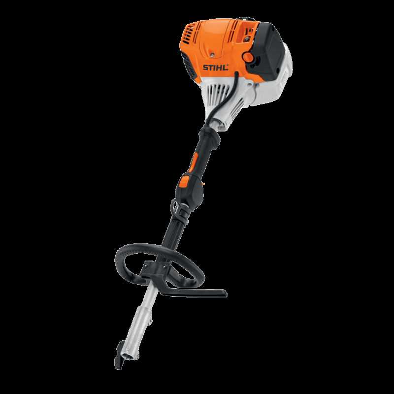
The drive shaft is a crucial element in the machinery, responsible for transferring power from the engine to various attachments. Understanding the components that make up this system is essential for ensuring efficient operation and maintenance. This section will provide insights into the key elements involved in the drive shaft assembly, highlighting their functions and significance.
Component Description Coupling A device that connects two shafts together, allowing for the transfer of torque while accommodating misalignment. Universal Joint A flexible joint that allows for rotation and angular movement between two shafts, helping to maintain power transfer at varying angles. Drive Shaft Tube The hollow cylindrical part that houses the inner components and provides structural integrity to the assembly. Bearings Support elements that reduce friction between moving parts, ensuring smooth operation of the drive shaft. End Fittings Connectors that secure the drive shaft to the engine and attachments, ensuring a reliable link for power transfer. Exhaust System Configuration

The configuration of the exhaust system is crucial for ensuring optimal performance and efficiency of the engine. It plays a significant role in managing emissions and noise levels while maintaining the required power output. Understanding the components and layout of this system is essential for effective maintenance and troubleshooting.
The primary elements of an exhaust setup include:
- Exhaust manifold: Collects exhaust gases from the engine cylinders.
- Exhaust pipes: Transport gases from the manifold to the muffler.
- Muffler: Reduces noise produced by the engine.
- Exhaust tip: The final outlet for exhaust gases, often designed for aesthetic appeal.
Proper alignment and connection of these components are vital to prevent leaks and ensure efficient gas flow. Regular inspection and maintenance of the exhaust system can significantly enhance the longevity of the engine and improve overall functionality.
Starter Assembly and Its Role
The starter assembly is a crucial component of many outdoor power tools, serving as the initial mechanism that engages the engine. Its proper functioning ensures that the tool operates efficiently and effectively. Understanding the structure and operation of this assembly is essential for anyone looking to maintain or troubleshoot their equipment.
Components of the Starter Assembly
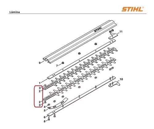
The starter assembly typically consists of several key elements, including the recoil starter, spring, and cord. The recoil starter is responsible for pulling the engine’s flywheel, initiating the combustion process. The spring provides the necessary tension to rewind the starter cord after each pull, ensuring that it is ready for the next attempt.
Importance of Maintenance
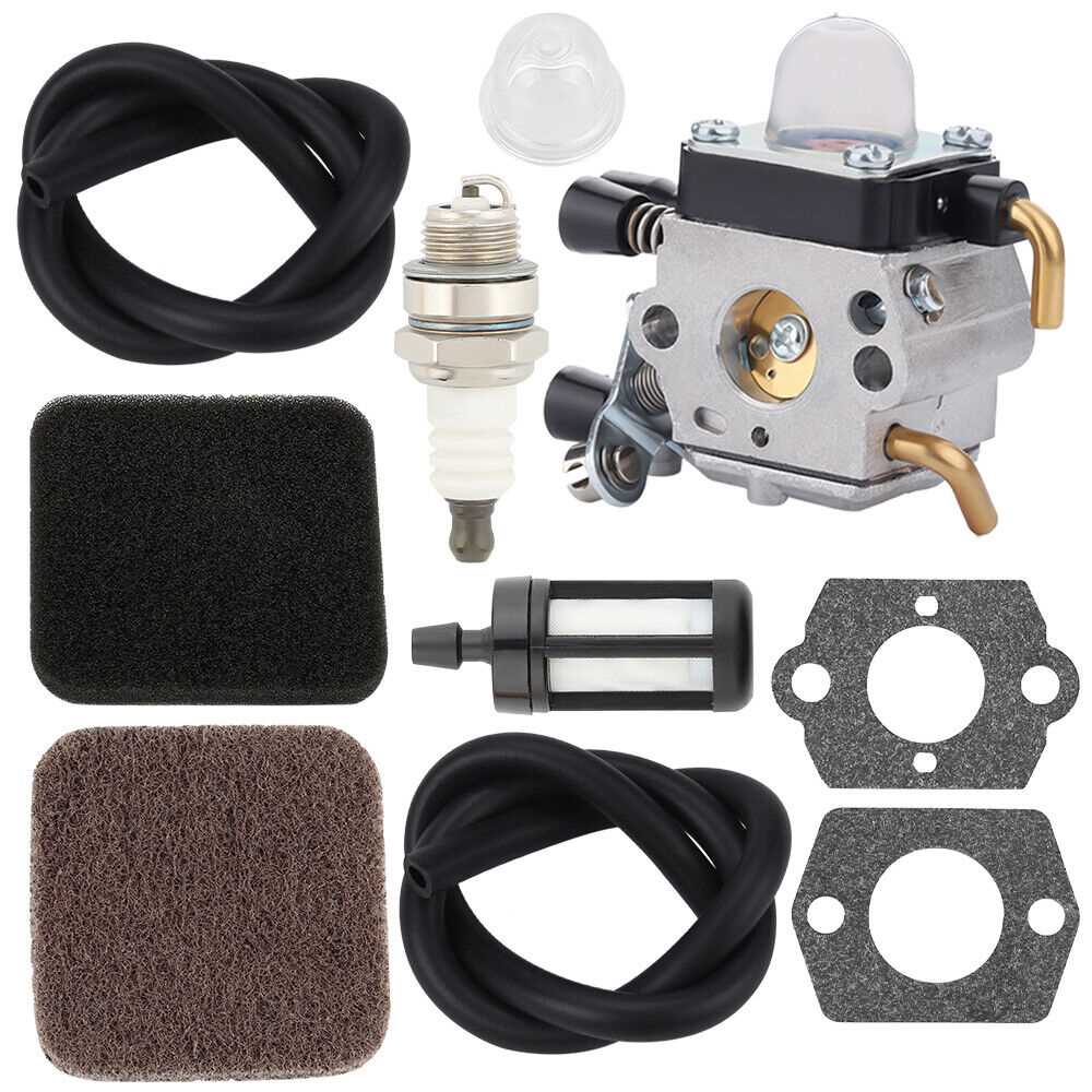
Regular maintenance of the starter assembly is vital for optimal performance. Over time, components may wear out or become damaged, leading to difficulties in starting the engine. Regularly inspecting the recoil starter and replacing any worn parts can significantly enhance the reliability and lifespan of the tool. Additionally, keeping the assembly clean and free of debris can prevent potential issues.
Common Replacement Parts for Stihl KM 85
Maintenance is crucial for keeping any outdoor power equipment running smoothly and efficiently. Knowing the typical components that may require replacement can help users maintain optimal performance and extend the life of their equipment. This section outlines the frequently needed elements for effective upkeep.
Component Description Signs of Wear Fuel Filter Prevents debris from entering the fuel system. Difficulty starting or engine stalling. Air Filter Filters out dust and dirt from the air intake. Reduced power or increased fuel consumption. Spark Plug Ignites the fuel-air mixture for combustion. Hard starting or misfiring engine. Trimmer Head Holds the cutting line and allows for easy line replacement. Difficulty in feeding the line or excessive wear. Drive Shaft Transmits power from the engine to the cutting attachment. Vibration or unusual noises during operation.