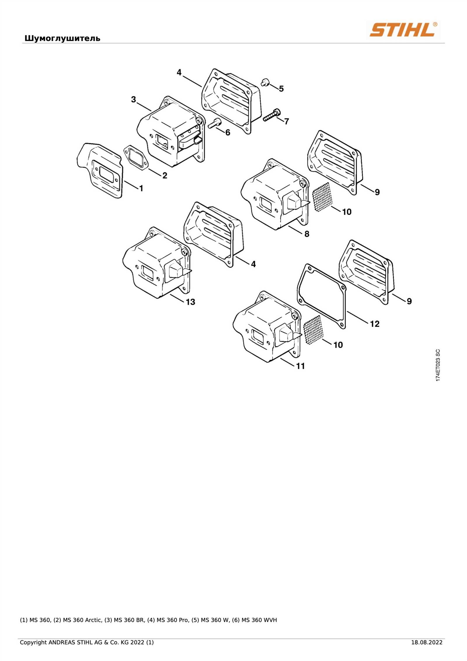
In this section, we will explore the intricate structure and configuration of a popular model from a renowned manufacturer. Whether you’re looking to maintain, repair, or enhance performance, understanding the internal and external elements of the equipment is crucial. By examining each part and its function, users can gain valuable insight into the machine’s workings, ensuring longevity and optimal efficiency.
The following guide will help you navigate through the detailed layout, allowing for precise identification of the necessary components. From power delivery mechanisms to safety features, each section plays a vital role in the machine’s overall functionality. This knowledge empowers users to make informed decisions when troubleshooting or performing maintenance tasks, ultimately enhancing their experience with the equipment.
Overview of Key Components
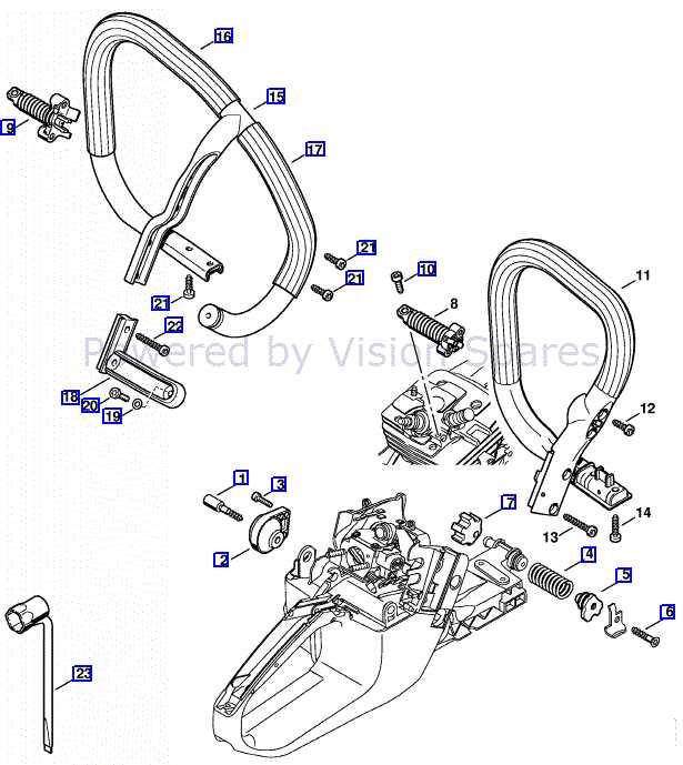
Understanding the essential elements of this tool is critical for maintaining its performance and ensuring smooth operation. The various mechanisms work in unison to deliver power and precision, making it a reliable choice for demanding tasks. Each section plays a pivotal role in driving efficiency and durability, from the engine to the safety systems.
Engine Assembly: The core of the machine, this section houses the driving force that powers the entire system. It’s responsible for generating the energy needed to perform efficiently, and its proper maintenance is crucial for long-term use.
Chain and Guide Bar: This combination ensures clean and controlled cutting. Proper alignment and tension are vital for achieving optimal results, and they require regular adjustments to maintain effectiveness.
Handle and Controls: The ergonomic design of the handle allows for ease of use, providing the operator with comfort and control. The
Understanding the Chain Mechanism
The cutting system plays a pivotal role in any machinery designed for outdoor tasks. To ensure efficient performance, it is crucial to comprehend how the interconnected elements of the cutting system work together. This section delves into the movement and coordination of these key components, offering insights into the intricate processes behind cutting efficiency and durability.
Chain Drive Operation: At the heart of the cutting system is the driving link. This element is responsible for transferring force, enabling smooth and controlled cutting action. The drive sprocket’s engagement with the links ensures that the chain remains taut and moves in a synchronized manner, directly affecting cutting precision.
Tension and Adjustment: Maintaining proper tension is essential for both safety and performance. Insufficient tension can lead to slippage, while excessive tightness increases wear. Regular inspection and fine-tuning of this aspect ensure the smooth operation of the mechanism, enhancing both efficiency and longevity.
Lubrication and Wear Prevention: The cutting mechanism’s components are subject to continuous friction, which can lead to premature wear. Proper lubrication reduces this friction, ensuring smoother movement and extending the lifespan of the moving parts. Keeping the system well-oiled also minimizes the risk of overheating and mechan
Guide Bar Maintenance Essentials
Ensuring that the key component responsible for the cutting process stays in top condition is crucial for both efficiency and safety. Regular upkeep not only extends its lifespan but also enhances performance, reducing wear and tear. A well-maintained guide ensures smooth operation and minimizes the risk of damage to other parts.
Cleaning and Inspection
Frequent cleaning helps remove debris and build-up that can cause friction and affect functionality. After each use, it is important to thoroughly inspect for any signs of wear, such as nicks or uneven surfaces. If damage is spotted, it’s essential to address the issue immediately to prevent further deterioration.
Proper Lubrication
Lubrication is another key aspect of guide maintenance. Consistently applying the right type of oil reduces friction and heat, ensuring smoother cuts and extending the overall lifespan of the equipment. Always check for the manufacturer’s recommendation on the type of lubricant and intervals of application for optimal results.
Tips for Ensuring Longevity
Maintaining proper care and consistent upkeep is essential for extending the lifespan of any mechanical tool. Ensuring that every component functions smoothly over time requires regular inspections, cleaning, and proper handling. With a few practical techniques, you can significantly enhance the durability and reliability of your equipment.
| Action | Frequency | Benefit |
|---|---|---|
| Regular cleaning | After each use | Prevents buildup and wear |
| Inspection of moving parts | Monthly | Avoids unexpected malfunctions |
| Lubrication of joints | Every 3 months | Reduces friction and wear |
| Replacement of worn components | As needed | Ensures smooth performance |
Internal Engine Structure Breakdown
The intricate layout of the internal components reveals the core mechanics that drive the overall functionality. Understanding the arrangement and interplay of the various moving parts within the system is essential for both maintenance and performance enhancement. Each element plays a critical role, ensuring that the machinery operates with precision and durability.
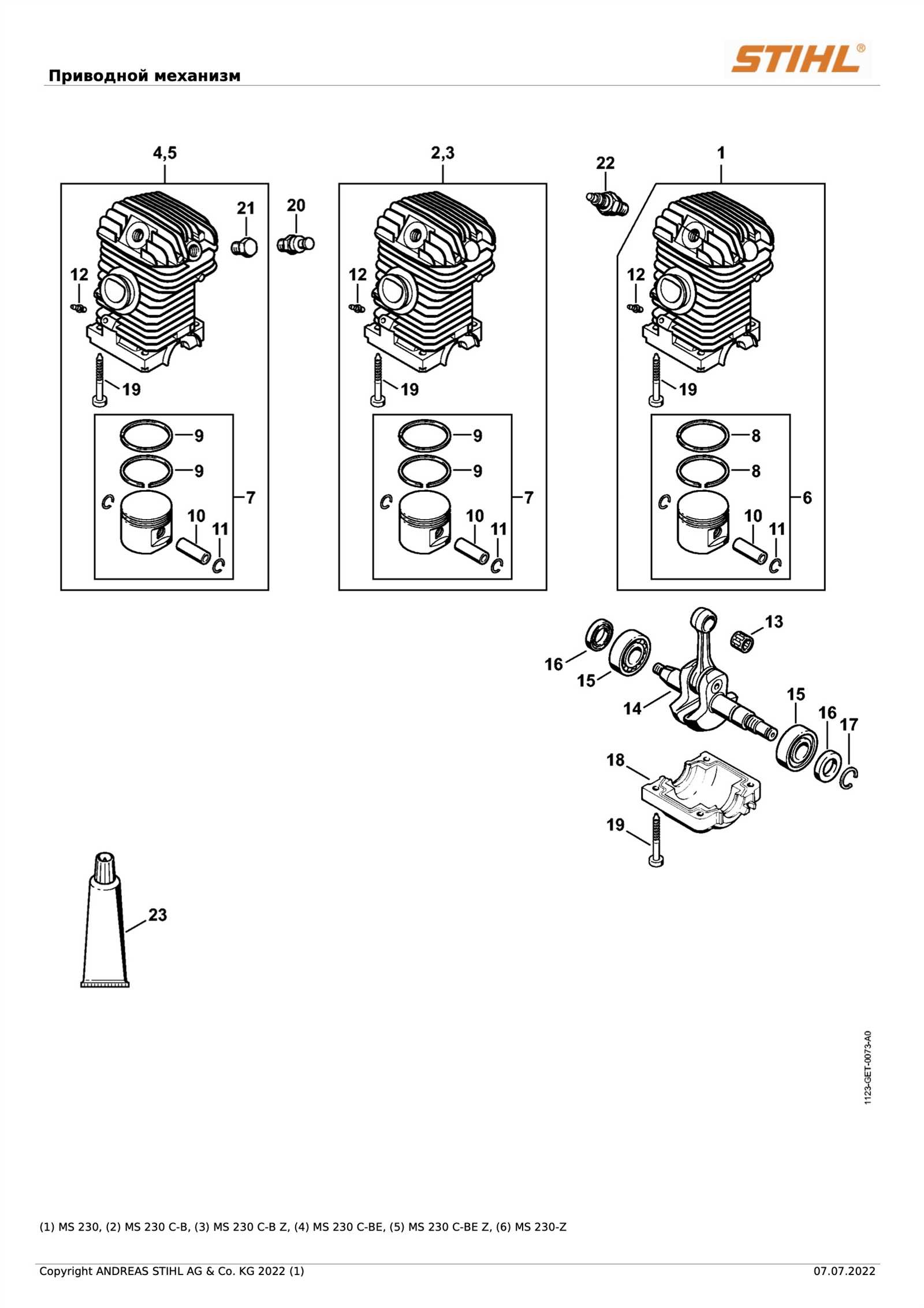
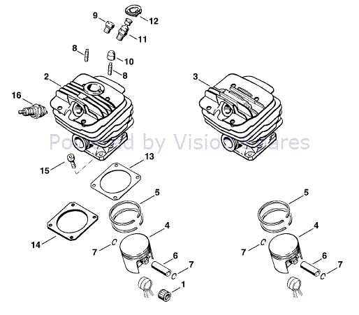
Cylinder and Piston Interaction: The primary mechanism relies on the seamless movement of the piston within the cylinder. This process generates the necessary force to power the entire system, transforming energy into mechanical output.
Crankshaft Operation: Connected to the piston, the crankshaft converts the linear motion into rotational energy. Its robust design and placement are vital for sustaining consistent performance, especially under demanding conditions.
Fuel Delivery System: Efficient delivery and regulation of the fuel mixture is crucial. The components involved in this process ensure optimal combustion, which directly influences engine power and efficiency.
These interconnected elements form the foundation of a well-tuned system, where each component contributes to a balanced and efficient operation.
Identifying Vital Engine Parts
Understanding the essential components of an engine is crucial for maintaining its performance and longevity. Each part plays a specific role in ensuring the engine operates smoothly and efficiently. This section will outline the key elements you need to be familiar with when assessing engine functionality.
- Crankshaft: This component converts linear motion into rotational energy, driving the engine’s pistons.
- Pistons: These cylindrical pieces move up and down within the cylinder, facilitating the combustion process.
- Cylinder Head: Located at the top of the cylinder, it houses the valves and spark plugs, playing a vital role in airflow and ignition.
- Fuel System: This includes the fuel tank, lines, and injectors, responsible for delivering the necessary fuel for combustion.
- Ignition System: Comprising spark plugs and coils, this system generates the spark needed to ignite the air-fuel mixture.
Each of these components contributes to the overall efficiency and reliability of the engine. Regular inspection and understanding of these parts can help diagnose issues and prevent potential failures.
Fuel System and Its Functionality
The fuel mechanism plays a vital role in the efficient operation of outdoor power equipment, ensuring that the engine receives the necessary energy for optimal performance. This system is intricately designed to deliver a precise mixture of fuel and air, which is essential for the combustion process. A well-functioning fuel system enhances engine reliability and longevity, making it an indispensable component of the overall machinery.
This assembly typically includes a fuel tank, filter, lines, and a carburetor or injection system. Each element contributes to the effective management of fuel flow, preventing contaminants from entering the engine and maintaining the correct pressure for combustion. Regular maintenance of these components is crucial for ensuring seamless operation and preventing issues that may arise from fuel contamination or blockages.
Moreover, the design of the fuel system allows for easy access and servicing, enabling users to perform necessary checks and replacements. Understanding the functionality and layout of this assembly can help users troubleshoot problems and maintain their equipment in peak condition, thereby enhancing productivity and performance during operation.
Common Issues and Troubleshooting
When working with outdoor power tools, encountering challenges is not uncommon. Identifying and resolving these issues promptly can enhance the tool’s performance and prolong its lifespan. This section addresses frequent problems that users may face and provides practical solutions to help keep the equipment running smoothly.
Engine Difficulties: One of the most prevalent concerns is engine failure to start. This can result from various factors, including insufficient fuel, a clogged air filter, or a faulty ignition system. Ensure that the fuel is fresh, check for blockages, and inspect the ignition components to resolve this issue.
Overheating: If the tool experiences excessive heat during operation, it may indicate a lack of lubrication or a dirty cooling system. Regularly clean the cooling fins and check the oil levels to prevent overheating, which can lead to severe damage.
Chain Problems: A common issue with cutting tools is chain malfunction. This can manifest as chain slippage or uneven cutting. Ensure the chain tension is properly adjusted and that it is adequately lubricated. Additionally, inspect the guide bar for wear and replace it if necessary.
Vibration: Excessive vibration during use can be uncomfortable and may signal underlying issues, such as unbalanced components or loose parts. Regularly inspect the equipment for wear and ensure all screws and bolts are tightened properly to minimize vibration.
By understanding these common challenges and implementing effective troubleshooting strategies, users can maintain optimal functionality and enhance the reliability of their outdoor power tools.
Ignition System Components Explained
The ignition system plays a vital role in ensuring the proper functioning of combustion engines. This system is responsible for initiating the combustion process, enabling the engine to operate efficiently. Understanding its various components is essential for maintenance and troubleshooting.
Key Components
- Ignition Coil: Converts low voltage from the battery into high voltage, generating the spark necessary for ignition.
- Spark Plug: Facilitates the spark that ignites the fuel-air mixture in the combustion chamber.
- Flywheel Magnet: Generates electrical energy as it rotates, providing power to the ignition coil.
- Trigger Module: Senses the position of the flywheel and signals the ignition coil to produce a spark at the right moment.
Additional Elements
- Wiring Harness: Connects various components of the ignition system, ensuring proper communication and power distribution.
- Ignition Switch: Allows the operator to start and stop the engine, controlling the power to the ignition system.
- Grounding System: Ensures the safe operation of the ignition system by preventing electrical shorts and overloads.
How to Test and Replace
Maintaining and ensuring the functionality of your equipment is crucial for optimal performance. Regularly assessing components can help identify issues early, preventing costly repairs and downtime. This section provides a guide on evaluating and substituting essential elements effectively.
Testing Components
Before replacing any part, it’s essential to perform thorough tests to determine whether replacement is necessary. Here are some common methods:
- Visual Inspection: Examine the component for signs of wear, damage, or corrosion.
- Functional Testing: Operate the equipment to check for irregularities in performance.
- Resistance Testing: Use a multimeter to measure electrical resistance and ensure it falls within the recommended range.
Replacing Components
If testing reveals that a component is defective, follow these steps for replacement:
- Gather Tools: Collect necessary tools such as screwdrivers, wrenches, and replacement parts.
- Disconnect Power: Ensure that the equipment is powered down to prevent accidents.
- Remove the Defective Part: Carefully take out the malfunctioning component, noting its position for reassembly.
- Install New Component: Place the new part in the same position as the old one, ensuring a secure fit.
- Test Functionality: Power up the equipment and perform a test run to confirm the new part operates correctly.
By following these guidelines, you can maintain your equipment’s efficiency and extend its lifespan.
Oil Pump and Lubrication System
The efficient operation of any machinery relies heavily on its ability to maintain proper lubrication throughout its components. A well-designed lubrication system ensures that moving parts are adequately coated with oil, reducing friction and wear. This is particularly crucial for tools that operate under significant stress and varying conditions.
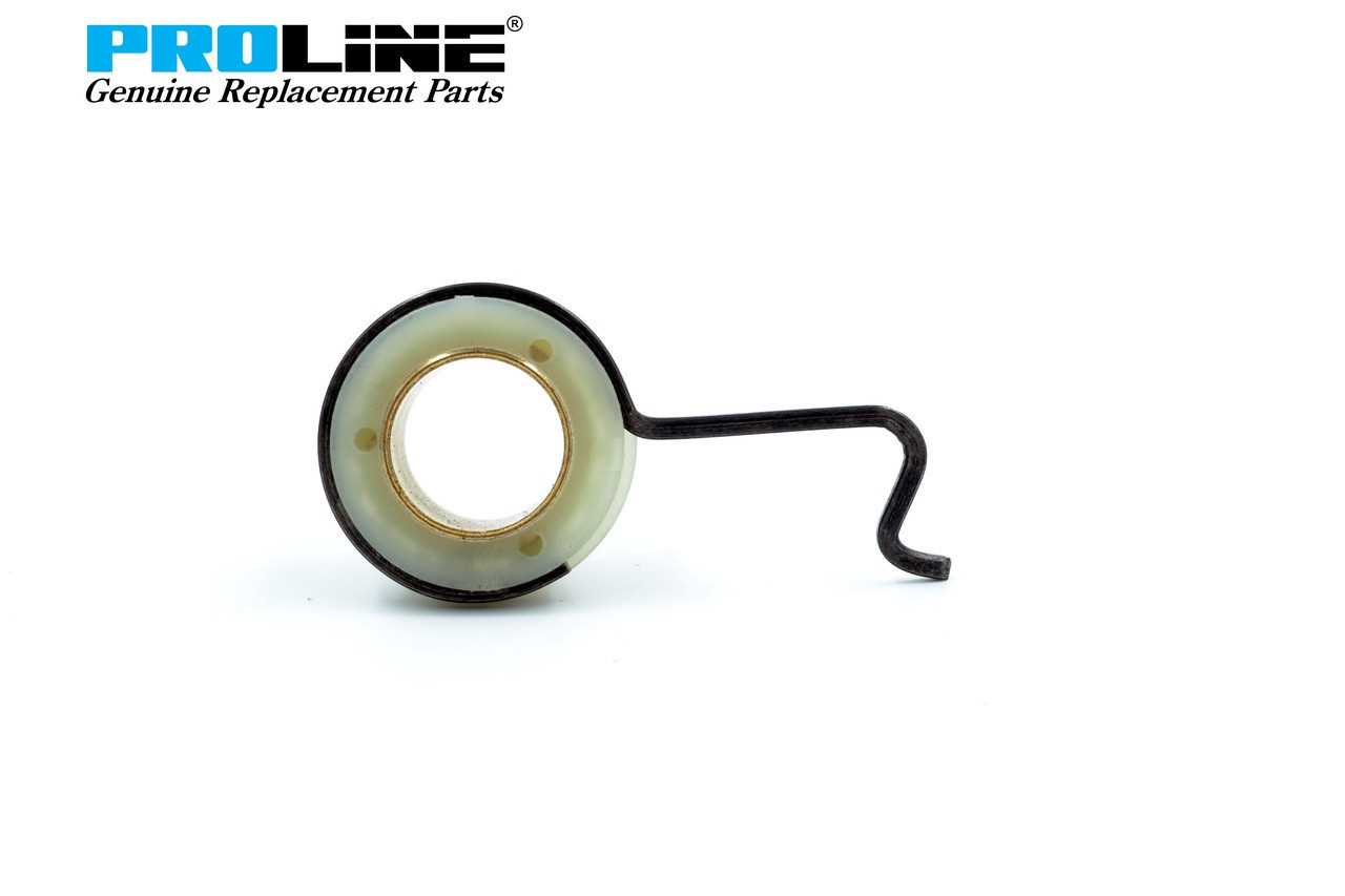
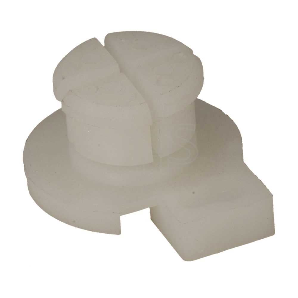
The oil pump plays a pivotal role in this system by delivering lubricant precisely where it is needed. Typically, these pumps are designed to adjust the flow rate based on the operational demands, ensuring optimal performance. As the engine runs, the pump circulates oil through channels, reaching critical areas such as bearings and gears, which helps to prevent overheating and damage.
Furthermore, the lubrication system often incorporates filters to remove contaminants from the oil, thus prolonging the life of both the lubricant and the equipment. Regular maintenance of the lubrication system is essential to ensure its efficiency, which includes checking oil levels, replacing filters, and inspecting the pump for any signs of wear or malfunction.
Preventing Common Malfunctions
Understanding the essential elements of maintenance is crucial for ensuring the longevity and efficiency of outdoor equipment. Regular care not only enhances performance but also helps avoid frequent breakdowns that can disrupt your tasks. This section outlines effective strategies to mitigate the risk of common issues.
Routine Maintenance Checks
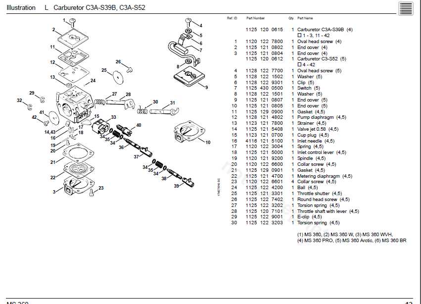
Frequent inspections are vital for identifying potential problems before they escalate. Pay close attention to components such as the air filter, fuel system, and chain tension. Keeping these parts clean and properly adjusted can significantly reduce the likelihood of operational failures.
Proper Usage Techniques
Employing correct handling practices can make a significant difference in performance and durability. Always follow the manufacturer’s guidelines regarding usage to prevent undue stress on the machinery. Using the equipment within its designed limits ensures optimal functionality and minimizes wear and tear.
Understanding the Carburetor Assembly
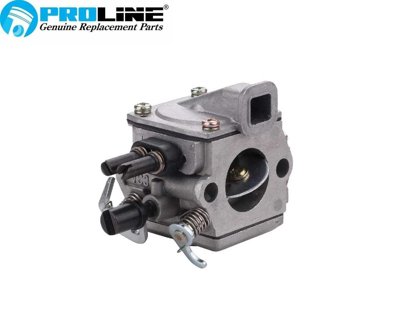
The carburetor assembly is a crucial component that plays a significant role in the overall functioning of small engines. Its primary function is to mix air and fuel in the correct ratio, ensuring optimal combustion and performance. A thorough understanding of its parts and operation can help in maintenance and troubleshooting.
Key Components of the Carburetor
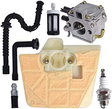
- Float Chamber: Regulates the fuel level, allowing for consistent operation.
- Jet: Controls the amount of fuel entering the airflow, affecting the mixture.
- Throttle Valve: Adjusts the air-fuel mixture based on the engine’s demand for power.
- Choke: Aids in starting the engine by enriching the fuel mixture.
How the Carburetor Works
The operation begins when the engine draws air through the carburetor. As air passes through, it creates a vacuum that draws fuel from the float chamber. The mixture of air and fuel is then directed into the combustion chamber. Proper adjustment of the components ensures efficient engine performance and responsiveness.
- Air enters the carburetor.
- A vacuum forms, drawing fuel from the float chamber.
- The air-fuel mixture travels to the combustion chamber.
- The engine ignites the mixture for power.