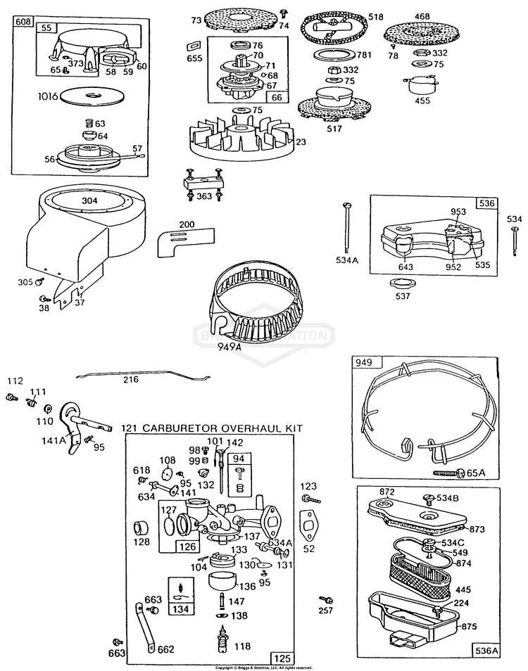
Understanding the inner workings of a dependable power unit is essential for maintaining its longevity and peak performance. This section offers a detailed look into key assemblies, focusing on the essential components that ensure smooth operation and minimal downtime.
We will navigate through various elements that play a crucial role in the overall functionality of this engine model. Identifying individual sections and their connections helps users efficiently address maintenance tasks and troubleshoot potential issues.
Whether you’re performing routine upkeep or replacing specific elements, having a clear view of the system’s layout is vital. Our breakdown ensures that each piece is described for easy identification, making future interventions more straightforward and effective.
Overview of Engine Assembly Components
This section introduces the main elements involved in the construction of a modern engine. Each component plays a vital role in ensuring smooth operation and maximizing efficiency. Understanding how these parts interact helps identify potential issues and maintain optimal performance.
Primary Functional Units
- Power Generation Module: Converts fuel into mechanical energy, driving the entire system.
- Air and Fuel System: Regulates the mixture required for efficient combustion.
- Ignition Mechanism: Triggers the combustion process at precise intervals.
Structural and Support Components
- Casing and Frame: Provides housing for internal elements and structural stability.
- Cooling Setup: Maintains safe operating temperatures to prevent overheating.
- Lubrication Network: Reduces friction and extends the lifespan of moving parts.
Proper care and timely inspection of these components ensure durability and reliability, reducing the need for frequent repairs or replacements.
Understanding Fuel System Connections
The arrangement of components within a fuel delivery setup ensures smooth operation by facilitating the transfer and regulation of combustible liquids. Proper alignment between the elements involved helps maintain efficiency, reduces emissions, and ensures the machinery operates without interruptions. A well-maintained fuel path minimizes risks related to blockages or leaks, contributing to overall performance.
Main Components in the Flow Path
Each element within the system plays a specific role, from storage units to delivery lines. Filters prevent debris from entering sensitive areas, while valves regulate the amount of liquid reaching the ignition area. Tubes and connectors link the various segments, ensuring uninterrupted movement of the liquid across all stages of operation.
Maintaining Seamless Flow
Regular inspections of connections are essential to avoid disruptions. Ensuring seals are intact and all pathways are clear can prevent malfunctions during operation. Replacing worn-out components on time helps sustain performance, ensuring that the fuel reaches the combustion area efficiently and safely.
Key Elements of Ignition Mechanism
The ignition system serves as the core process that initiates combustion, ensuring smooth operation by delivering the necessary spark at the right moment. It relies on the precise interaction of multiple components, which together regulate the energy flow essential for starting and maintaining the engine’s power cycle.
Primary Components Involved
A key feature of the mechanism is the spark generator, which creates the electrical pulse needed to ignite the air-fuel mixture. This pulse is regulated by a timing control, ensuring synchronization with the movement of internal parts. Any delay or misalignment here can result in starting issues or reduced efficiency.
Energy Transfer and Delivery
The system also relies on voltage converters to amplify the electrical charge, making it strong enough to bridge the gap between electrodes. Insulated conductors transfer this charge to the appropriate chamber, where the energy release occurs, setting the combustion process in motion.
Air Intake and Filtration Layout
The arrangement responsible for channeling airflow into the engine ensures smooth operation by guiding fresh air through protective layers. This setup minimizes contamination, contributing to efficient combustion and overall system longevity.
| Component | Description |
|---|---|
| Air Duct | Directs airflow toward the filtering mechanism, reducing the entry of large debris. |
| Filter Element | A porous medium that captures fine particles, preventing damage to internal components. |
| Housing Assembly | Encases the filter, ensuring stability and proper sealing for unimpeded airflow. |
| Intake Valve | Regulates the volume of air entering the combustion chamber. |
Oil Maintenance Components and Pathways
Ensuring smooth operation of internal mechanisms requires regular attention to the lubrication system. Key elements involved in this process contribute to the steady distribution and filtration of fluid, minimizing friction and wear over time. Understanding the interaction between these components helps maintain performance and extend equipment longevity.
Primary Lubrication Elements
The core elements consist of the fluid reservoir, pump assembly, and filtering mechanism. The pump ensures consistent circulation, while the filter removes contaminants, preserving the quality of the lubricant. These parts work in tandem to prevent internal blockages and ensure seamless operation.
Circulation Pathways and Flow Management
Fluid movement follows a predefined route, guided through valves and channels designed to regulate pressure. Critical areas receive lubricant first, reducing heat and friction during operation. Proper flow management guarantees even distribution, preventing premature wear of essential components.
Starter System Design and Operation
The starter mechanism is a critical component in the overall functionality of small engine systems. Its primary role is to initiate the engine’s operation, allowing for a smooth transition from standby to active running status. This system typically involves various components that work in harmony to ensure reliable performance.
The design of a starter system generally includes the following key elements:
- Motor: The electric motor generates the necessary torque to turn the engine’s flywheel.
- Gear Reduction: A set of gears that amplifies the motor’s torque, ensuring sufficient force to start the engine.
- Solenoid: An electromagnetic switch that engages the starter motor when the ignition is activated.
- Battery: Supplies electrical energy to the starter motor and solenoid, enabling the system to function.
- Wiring Harness: Connects all components and facilitates the flow of electrical current.
The operation of this system can be summarized in several steps:
- The operator engages the ignition switch, sending a signal to the solenoid.
- The solenoid activates, closing the circuit and powering the starter motor.
- The motor engages with the engine’s flywheel through the gear reduction mechanism.
- The motor rotates the flywheel, initiating the engine’s combustion process.
- Once the engine is running, the system disengages, allowing the starter motor to stop functioning until the next activation.
Understanding the intricacies of the starter system aids in troubleshooting and maintaining engine performance, ensuring that it operates reliably throughout its service life.
Valve Mechanism Structure and Functionality
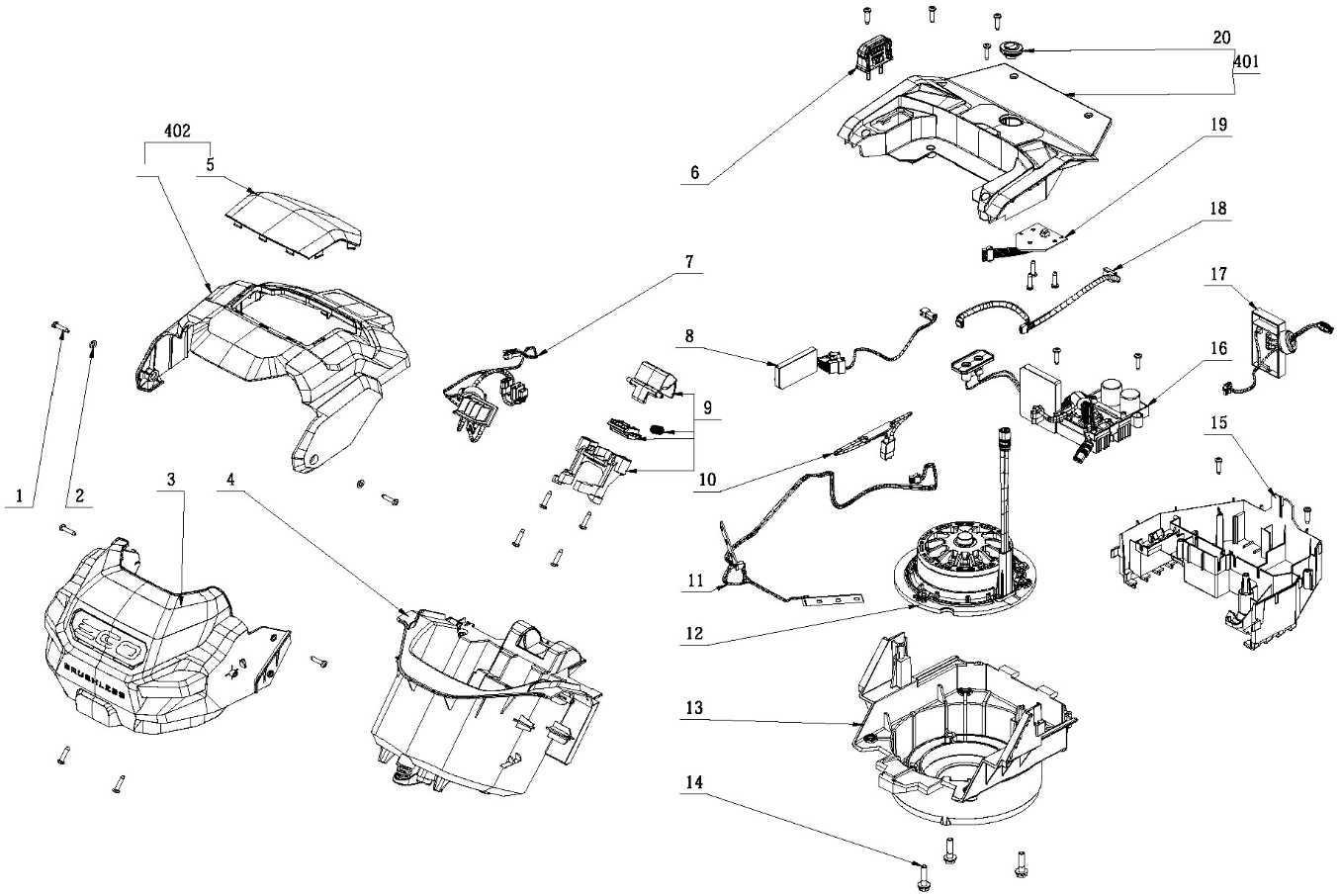
The valve mechanism plays a crucial role in controlling airflow and fuel mixture within an internal combustion engine. This system ensures that the intake and exhaust processes occur at precise intervals, contributing to the overall efficiency and performance of the engine. Understanding the components and their interactions is essential for optimizing engine function.
| Component | Function |
|---|---|
| Camshaft | Controls the opening and closing of valves through a rotating motion. |
| Valves | Regulate the intake of air-fuel mixture and the expulsion of exhaust gases. |
| Valve Springs | Provide the necessary force to close the valves after they have been opened. |
| Push Rods | Transmit motion from the camshaft to the valves in overhead valve designs. |
| Lifters | Maintain contact with the camshaft and ensure smooth movement of the push rods. |
Each component works harmoniously to ensure optimal engine performance. By precisely timing the opening and closing of the valves, this mechanism enhances the combustion process, leading to better fuel efficiency and reduced emissions.
Cooling System Parts and Configuration
The effectiveness of a cooling mechanism is vital for maintaining optimal operating temperatures in engines. Understanding the individual components and their arrangements can significantly enhance performance and longevity. This section delves into the essential elements that contribute to the overall functionality of the cooling mechanism, ensuring reliable operation during various tasks.
Essential Components
Key elements include the radiator, fan, and coolant pathways, each playing a crucial role in dissipating heat generated during engine operation. The radiator serves as the primary heat exchanger, facilitating efficient temperature regulation. Additionally, the fan ensures adequate airflow, further enhancing cooling efficiency, while the coolant pathways facilitate the circulation of the cooling fluid, effectively removing excess heat from critical areas.
Configuration and Arrangement
The arrangement of these components is equally important for optimal performance. Proper positioning of the radiator and fan can significantly influence airflow patterns, enhancing the cooling effect. Furthermore, the design of coolant pathways should minimize restrictions to ensure smooth fluid flow, which is essential for efficient heat transfer. This careful configuration contributes to the overall effectiveness of the cooling system, promoting reliable engine operation.
Muffler Assembly and Noise Control
The assembly responsible for sound reduction plays a crucial role in the functionality of outdoor power equipment. This component not only minimizes engine noise but also enhances overall performance by ensuring efficient exhaust flow. Understanding the structure and operation of this system is essential for maintaining optimal equipment performance and compliance with noise regulations.
Components of the Sound Reduction System
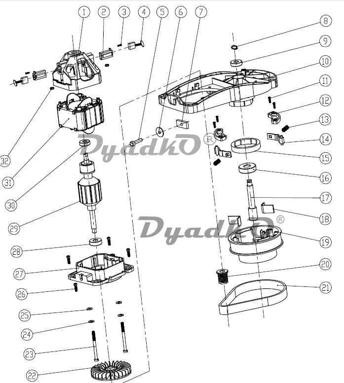
The noise suppression mechanism typically includes several key elements, such as the main body, inlet and outlet pipes, and internal baffles. These parts work together to dissipate sound waves generated during engine operation. The design may vary based on the specific model, but the fundamental principles of sound attenuation remain consistent across different systems.
Importance of Regular Maintenance
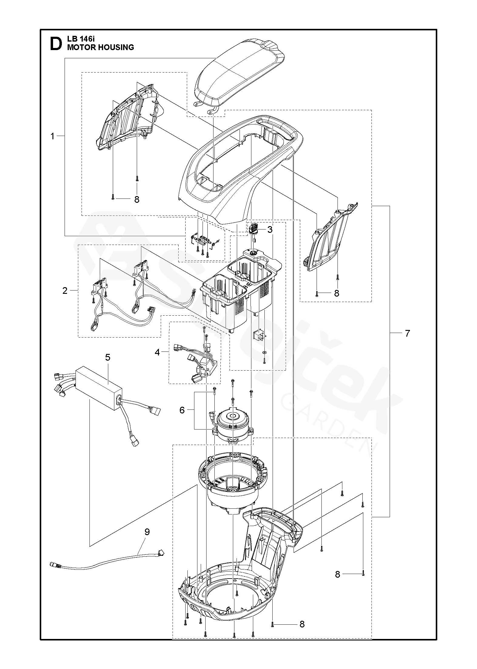
Routine inspection and maintenance of the sound control assembly are vital for ensuring its longevity and effectiveness. Regular cleaning, checking for damage, and replacing worn components can significantly reduce noise levels and enhance engine efficiency. Neglecting this aspect may lead to increased noise pollution and potential damage to the equipment, emphasizing the importance of proactive care.
Throttle Linkage and Control Overview
This section provides a comprehensive understanding of the components responsible for regulating the engine’s speed and power output. The linkage mechanism is crucial for maintaining optimal performance, allowing for precise adjustments in response to user input. By facilitating the connection between the control lever and the throttle valve, it ensures smooth operation and enhances the overall functionality of the engine.
Mechanism Functionality
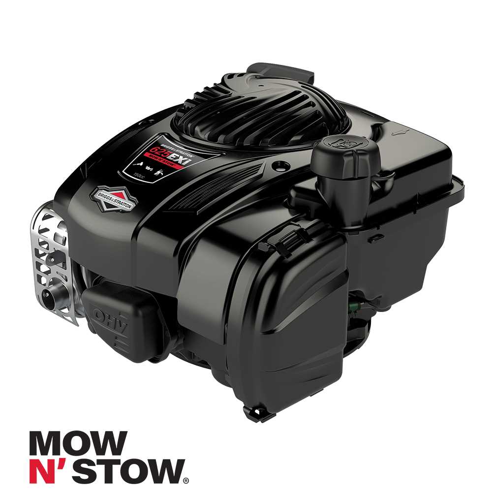
The functionality of the linkage system is pivotal for effective engine management. When the operator engages the control lever, it triggers a series of movements through the interconnected rods and levers. This action translates directly to the throttle valve’s position, enabling the engine to either increase or decrease its speed accordingly. Understanding this mechanism is essential for troubleshooting and ensuring peak performance.
Common Issues and Solutions
Several issues can arise within the linkage system, leading to performance inconsistencies. Common problems include misalignment, wear and tear on components, or a lack of lubrication. Regular maintenance and inspection can mitigate these issues. Identifying worn parts and replacing them promptly can restore functionality, while ensuring that all connections are secure will prevent operational failures.
Common Replacement Parts for Wear
When maintaining small engines, understanding which components may require frequent substitution is essential for ensuring optimal performance. Over time, various elements of the machinery can experience degradation due to regular use, environmental factors, and operational stresses. Identifying these components allows for proactive maintenance, reducing the risk of unexpected breakdowns.
One of the most commonly affected items is the air filter. This element plays a crucial role in maintaining airflow to the engine while preventing debris from entering. A clogged or damaged filter can lead to reduced efficiency and potential engine damage. Regular inspection and replacement of the air filter are recommended to keep the engine running smoothly.
Another critical component is the spark plug. It ignites the fuel-air mixture, and over time, it can wear out or become fouled with carbon deposits. Regularly changing the spark plug ensures reliable starting and optimal combustion, ultimately enhancing engine performance.
The fuel filter is also vital, as it protects the engine from contaminants present in the fuel. A compromised fuel filter can lead to fuel flow issues, causing the engine to sputter or stall. Regular replacement helps maintain fuel system integrity.
Lastly, consider the belts and cables. These components can fray or become brittle due to exposure to heat and mechanical wear. Inspecting these items regularly and replacing them as needed can prevent operational issues and ensure the longevity of the engine.