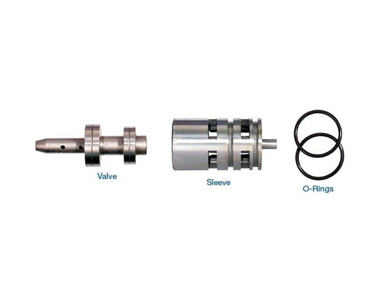
In the realm of automotive mechanics, understanding the intricate workings of a heavy-duty gearbox is essential for both enthusiasts and professionals. The complexity of these systems can often be daunting, but a comprehensive examination reveals the various elements that contribute to their functionality. Familiarity with these components enhances maintenance efforts and improves overall performance.
When delving into the specifics, one finds a multitude of gears, clutches, and assemblies that work in harmony to ensure smooth operation. Each element plays a pivotal role, from the intricate arrangement of gears that dictate power transfer to the essential hydraulic systems that facilitate seamless shifting. A visual representation can greatly aid in grasping the interconnections and functions of these critical elements.
By familiarizing oneself with these components, one gains valuable insight into troubleshooting and repair. Understanding how each piece interacts with the others can lead to more effective diagnostics and maintenance strategies. As you explore the various components, keep in mind that even the smallest part can have a significant impact on performance and reliability.
Understanding 4L80E Transmission Components
Gaining insight into the various elements that comprise a specific type of automatic gear mechanism is essential for effective maintenance and repair. Each component plays a crucial role in the overall functionality and performance, contributing to a seamless driving experience. By examining these elements, one can better appreciate their functions and how they interact within the system.
The following list highlights key components commonly found in this particular assembly:
- Torque Converter: This device facilitates the transfer of power from the engine to the gearbox, allowing for smooth acceleration.
- Clutch Packs: These enable the engagement and disengagement of gears, allowing for precise shifting.
- Valve Body: Acts as the control center, directing hydraulic fluid to various components for proper operation.
- Oil Pump: Ensures the circulation of transmission fluid, which lubricates and cools the system.
- Planetary Gear Set: A complex arrangement that provides the various gear ratios necessary for efficient operation.
Understanding these elements helps in diagnosing issues and performing necessary repairs, ensuring longevity and optimal performance of the assembly. Each component works in harmony, showcasing the intricate engineering behind modern automotive technology.
Key Elements of 4L80E Design
The design of this heavy-duty automatic gearbox encompasses several critical components that contribute to its efficiency and reliability. Understanding these fundamental elements can provide insights into its overall performance and adaptability for various applications.
Core Components
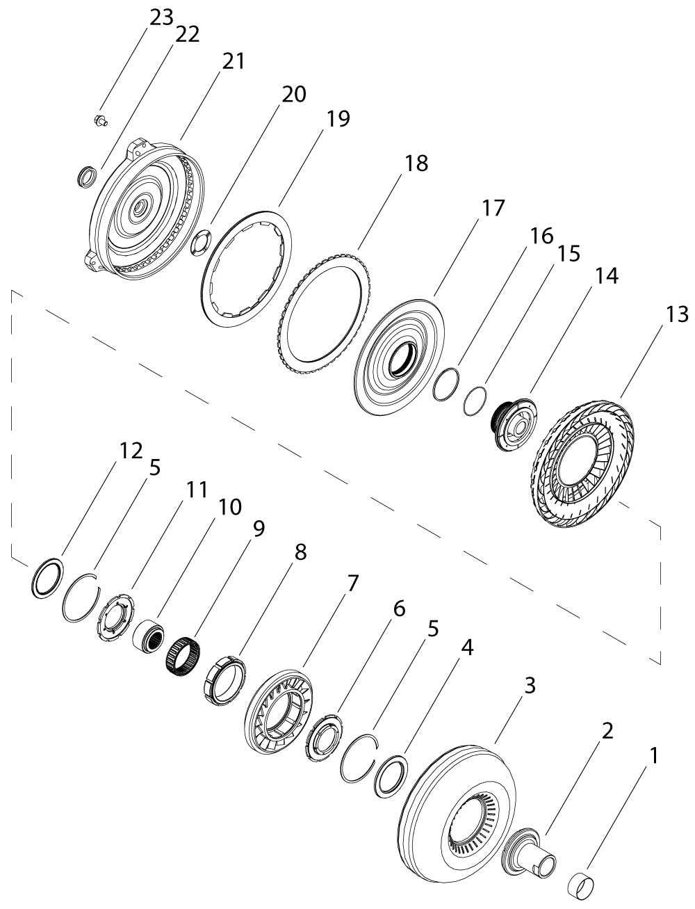
- Hydraulic System: Responsible for the seamless engagement and disengagement of gears, ensuring smooth shifts.
- Gear Set: The arrangement of gears that determines the gear ratios, affecting torque and speed.
- Valve Body: A crucial assembly that directs hydraulic fluid to the appropriate channels for shifting.
- Torque Converter: Facilitates the transfer of engine power to the gearbox while allowing for torque multiplication.
Construction Materials
- Aluminum: Commonly used for the casing due to its lightweight and resistance to corrosion.
- Steel: Utilized in gear and clutch construction for enhanced durability and strength.
- Composite Materials: Employed in seals and gaskets to ensure effective sealing and reduce friction.
Transmission Assembly and Layout
The arrangement and components of an automotive gear system play a crucial role in the efficiency and performance of a vehicle. Understanding the structure and configuration is essential for effective maintenance and troubleshooting. This section delves into the assembly’s key elements and their interrelations, providing insights into how they work together to ensure optimal functionality.
Key Components Overview
Each element within the gear system serves a distinct purpose, contributing to the overall operation. The main assemblies include the housing, gear sets, clutches, and servos. Each component is meticulously designed to withstand the mechanical stress and heat generated during operation. A well-designed layout not only enhances performance but also facilitates easier repairs and replacements.
Assembly Interaction
Understanding how the various assemblies interact is vital for diagnosing issues and performing upgrades. For instance, the synchronization between clutches and gear sets ensures smooth transitions during gear shifts. Moreover, the alignment of components within the housing is critical to prevent leaks and maintain proper fluid flow, which is essential for cooling and lubrication. Regular inspections and knowledge of the layout can significantly prolong the lifespan of these mechanical systems.
Function of Each Part Explained
This section provides an overview of the essential components found within a certain automotive system, focusing on their individual roles and contributions to overall functionality. Understanding how each element operates can enhance one’s grasp of the system’s mechanics and improve maintenance and troubleshooting efforts.
Key Components and Their Functions
- Case: The primary structure that houses all internal components, providing protection and support.
- Planetary Gear Set: Responsible for varying gear ratios, allowing for smooth acceleration and deceleration.
- Torque Converter: Facilitates the transfer of power from the engine to the assembly, enhancing efficiency and performance.
- Clutches and Bands: Engages and disengages different gear sets, enabling seamless shifting.
- Oil Pump: Maintains lubrication and hydraulic pressure, crucial for operation and longevity.
- Valve Body: Controls fluid flow and directs hydraulic pressure to appropriate components based on the current driving conditions.
Additional Elements
- Filter: Removes contaminants from the fluid, ensuring smooth operation and reducing wear.
- Sensors: Monitor various parameters, providing data that informs adjustments for optimal performance.
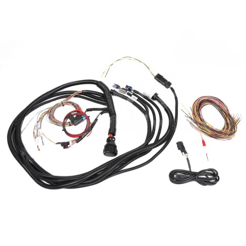
- Electrical Connectors: Facilitate communication between different systems, crucial for modern functionalities.
Each component works in harmony with others to achieve desired performance levels, highlighting the intricate engineering behind automotive systems.
Common Issues in 4L80E Units
Many vehicle owners encounter a variety of challenges with their automatic gear-shifting systems, which can lead to performance problems and increased wear. Understanding these frequent issues is essential for maintaining optimal functionality and ensuring a smooth driving experience. From electronic malfunctions to mechanical failures, several factors contribute to the degradation of these complex assemblies.
One prevalent concern is overheating, often resulting from inadequate fluid levels or poor cooling systems. When the temperature rises excessively, it can cause significant damage to internal components, leading to costly repairs. Another issue that arises is slipping, which can manifest as a delay in gear engagement or unexpected shifts. This often stems from worn-out clutches or faulty hydraulic pressure, necessitating immediate attention.
Moreover, leaks can pose a serious threat to overall operation. Fluid leaks diminish the hydraulic pressure required for proper function, resulting in inefficient gear changes. Additionally, the presence of electrical faults, such as sensor failures, can disrupt the system’s ability to communicate effectively, leading to erratic performance. Regular maintenance and timely inspections are crucial for identifying and addressing these common challenges, ultimately prolonging the lifespan of the assembly.
Maintenance Tips for Longevity
Proper upkeep is essential for ensuring the durability and efficiency of your vehicle’s powertrain components. By following a few simple guidelines, you can extend the lifespan of your system and prevent costly repairs in the future.
Regular Fluid Changes
Changing fluids at recommended intervals is crucial for optimal performance. Ensure you:
- Use high-quality fluids that meet manufacturer specifications.
- Check fluid levels frequently to prevent overheating and contamination.
- Replace filters alongside fluid changes to maintain cleanliness.
Routine Inspections
Frequent assessments of the system can identify potential issues early. Consider the following:
- Look for leaks or signs of wear around seals and gaskets.
- Inspect electrical connections and harnesses for fraying or damage.
- Monitor performance metrics, such as shifting smoothness and response times.
By adhering to these maintenance practices, you can enhance the reliability and efficiency of your system, ensuring it performs optimally for years to come.
Replacement Parts and Their Functions
The components of a vehicle’s power delivery system play a crucial role in ensuring smooth and efficient operation. Understanding the various elements that may require replacement helps maintain optimal performance and prolongs the lifespan of the entire system. Each item serves a distinct purpose, contributing to the overall functionality and reliability of the vehicle.
Among the essential elements are clutches, which engage and disengage different gear sets, allowing for seamless transitions during operation. Bearings reduce friction between moving parts, enhancing efficiency and reducing wear over time. Additionally, seals prevent fluid leaks, safeguarding the internal components from contamination and ensuring proper lubrication.
Other vital components include valves, responsible for regulating fluid flow and pressure, and case assemblies, which house and protect various internal parts from damage. Understanding the function of each element is essential for effective maintenance and timely replacements, ensuring the system operates at peak performance.
Diagram Interpretation for DIY Repairs
Understanding visual representations of mechanical assemblies is crucial for successful self-repair projects. These illustrations serve as invaluable resources, guiding enthusiasts through intricate disassemblies and reassemblies. By familiarizing oneself with these visuals, individuals can accurately identify components and their functions, leading to more effective troubleshooting and maintenance.
When approaching the visual layout, start by examining the various elements depicted. Each symbol and line conveys specific information about how components interact. Recognizing these details allows for a more informed approach when diagnosing issues or replacing elements. It is essential to note the orientation and placement of each section, as this directly impacts functionality.
| Component | Description | Function |
|---|---|---|
| Clutch Assembly | Central unit responsible for engaging and disengaging power | Controls the transfer of torque |
| Valve Body | Complex network of channels directing fluid flow | Regulates pressure for shifting |
| Gear Set | System of gears that adjusts output speed | Influences overall performance ratios |
By breaking down the illustration into its fundamental components and understanding their roles, DIYers can approach repairs with greater confidence and precision. Whether replacing a malfunctioning part or conducting routine maintenance, a thorough comprehension of these visual guides is essential for achieving successful outcomes.
Tools Required for Disassembly
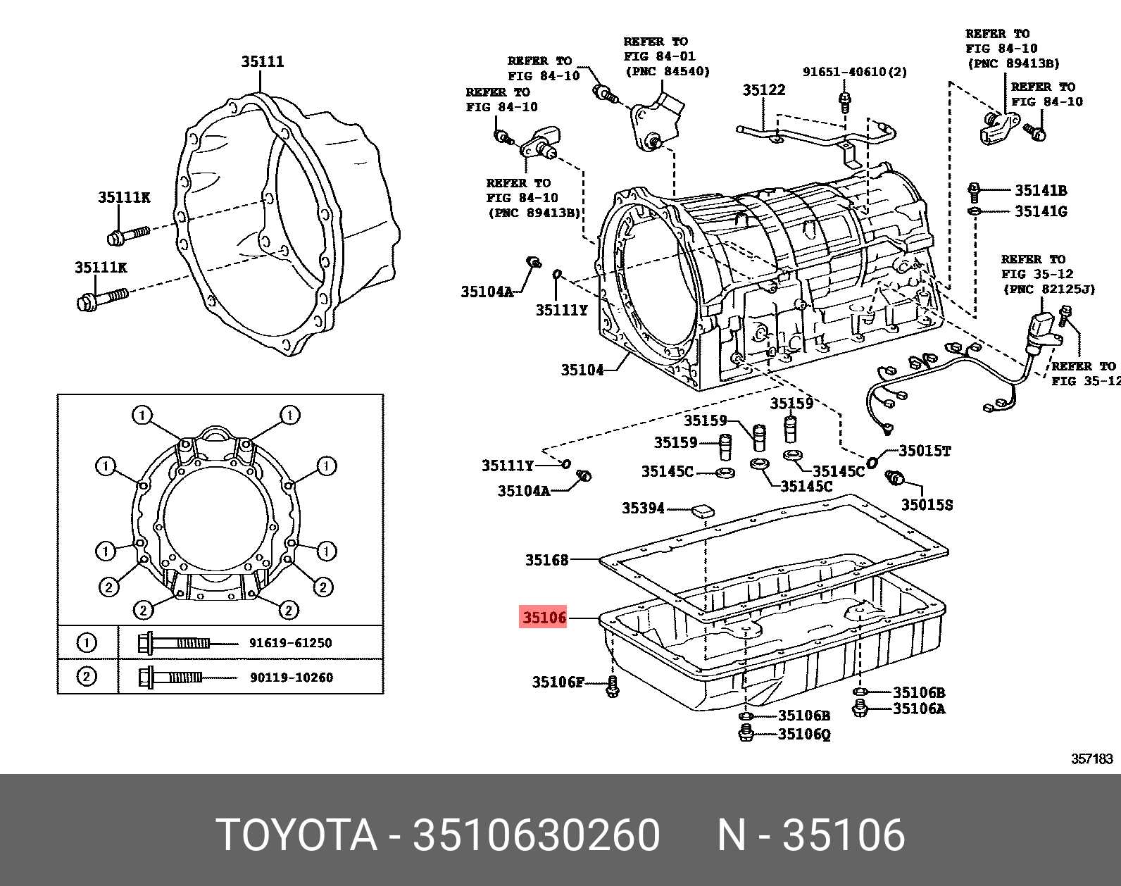
Successfully dismantling complex machinery requires specific instruments to ensure precision and efficiency. This section outlines the essential tools needed for the breakdown process, emphasizing the importance of proper equipment to prevent damage to components and facilitate smooth reassembly.
Essential Hand Tools
Having the right hand tools is critical when approaching the disassembly task. The following list includes the most commonly used instruments:
| Tool | Purpose |
|---|---|
| Socket Wrench Set | For loosening and tightening bolts and nuts of various sizes. |
| Screwdriver Set | To remove screws and access internal components. |
| Pliers | For gripping, twisting, and cutting wires or small components. |
| Torque Wrench | To apply specific torque values when reassembling. |
Specialized Equipment
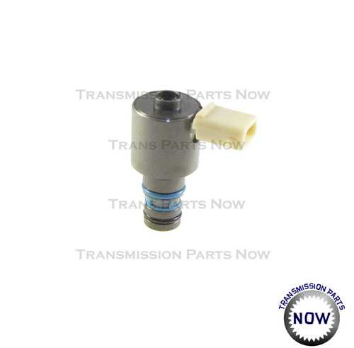
In addition to standard hand tools, certain specialized equipment may be necessary for more intricate tasks. These tools enhance the efficiency of the disassembly process:
| Tool | Purpose |
|---|---|
| Gear Puller | For removing gears or pulleys without damaging adjacent components. |
| Impact Gun | To quickly remove stubborn bolts or fasteners. |
| Cleaning Kit | For ensuring that all parts are free from dirt and debris before reassembly. |
Upgrades for Enhanced Performance
Optimizing the functionality and efficiency of your vehicle’s drive system is essential for those seeking to boost performance. Various enhancements can be made to improve responsiveness, durability, and overall driving experience. By focusing on key components, you can achieve remarkable results, whether for daily driving or competitive racing.
High-Performance Clutches and Bands
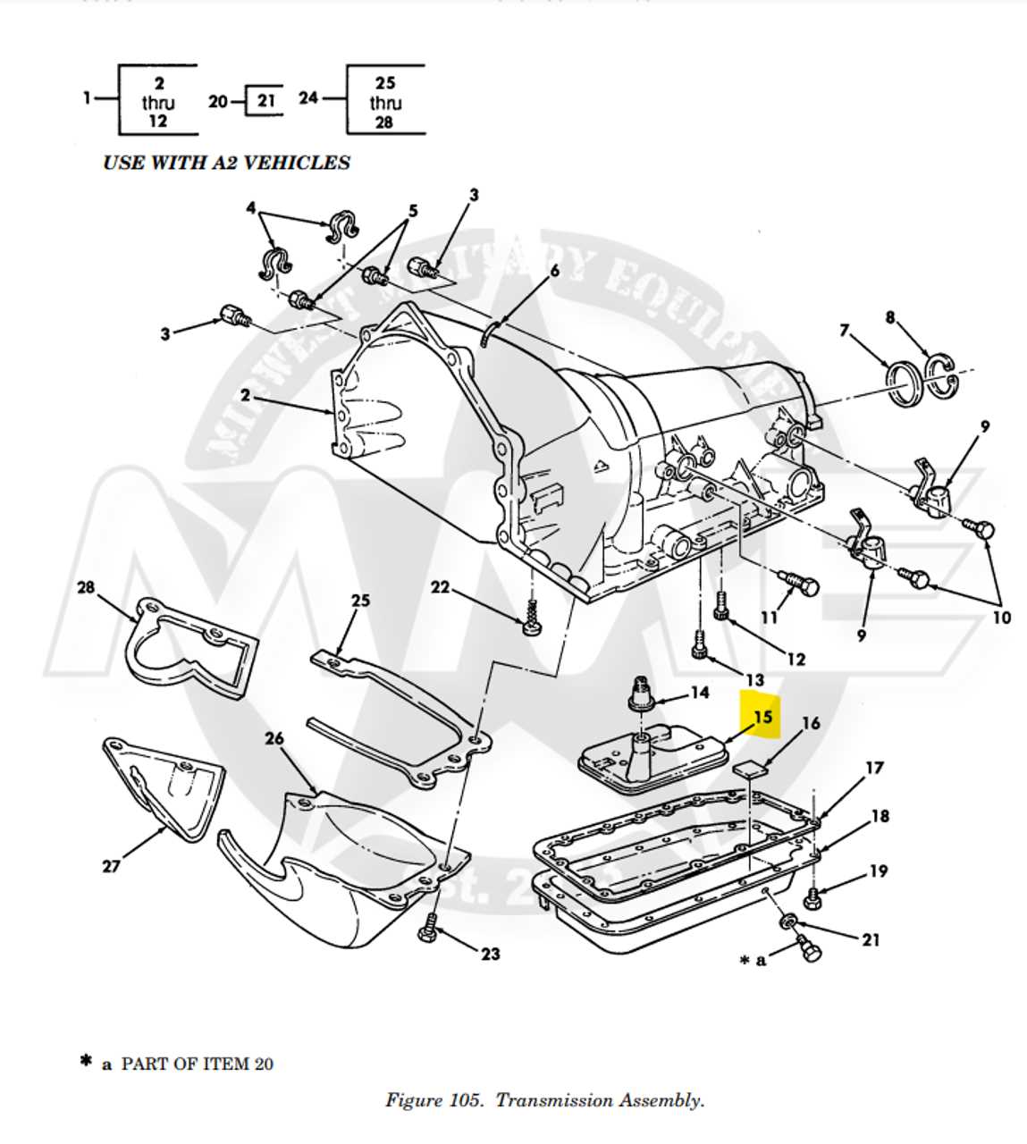
Clutch and band upgrades play a crucial role in enhancing the torque handling capabilities of the system. High-performance alternatives offer better grip and less slippage, allowing for smoother shifts and improved power transfer. Investing in premium materials and designs will provide greater reliability, especially under heavy loads or high-stress conditions.
Improved Valve Body and Tuning
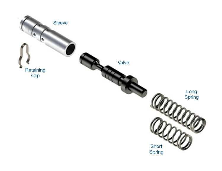
Reworking the valve body can significantly enhance the shifting characteristics. A modified valve body allows for quicker and more precise gear changes, improving acceleration and responsiveness. Additionally, tuning the control mechanisms can optimize pressure and flow rates, leading to a more dynamic driving experience. Adopting such enhancements ensures that your vehicle can handle increased power without compromising on performance.
Comparing 4L80E with Other Transmissions
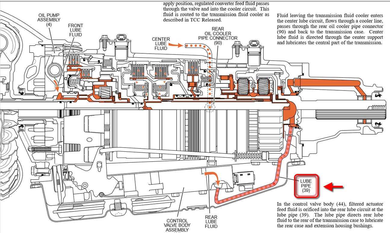
This section delves into the distinctions between a specific model of automatic gearbox and its counterparts in the market. Understanding the differences in design, performance, and application is essential for making informed decisions, whether for repairs, upgrades, or replacements. Each type of gearbox serves unique purposes and presents various advantages, catering to different driving styles and vehicle requirements.
Key Features and Benefits
When evaluating automatic gearboxes, several aspects stand out, including durability, efficiency, and adaptability. Below is a comparison of notable features among various models:
| Feature | Model A | Model B | Model C |
|---|---|---|---|
| Torque Capacity | 400 lb-ft | 450 lb-ft | 500 lb-ft |
| Gear Ratios | 3.06:1 | 3.08:1 | 3.07:1 |
| Weight | 140 lbs | 150 lbs | 145 lbs |
| Common Applications | Light Trucks | Heavy-Duty Trucks | Performance Vehicles |
Performance Considerations
In terms of performance, each gearbox has its unique strengths that cater to different types of vehicles and driving conditions. Factors such as shift responsiveness, heat management, and overall reliability play a significant role in selecting the right model for specific applications. Careful consideration of these elements can enhance the driving experience and ensure optimal vehicle performance.
Rebuilding Process Overview
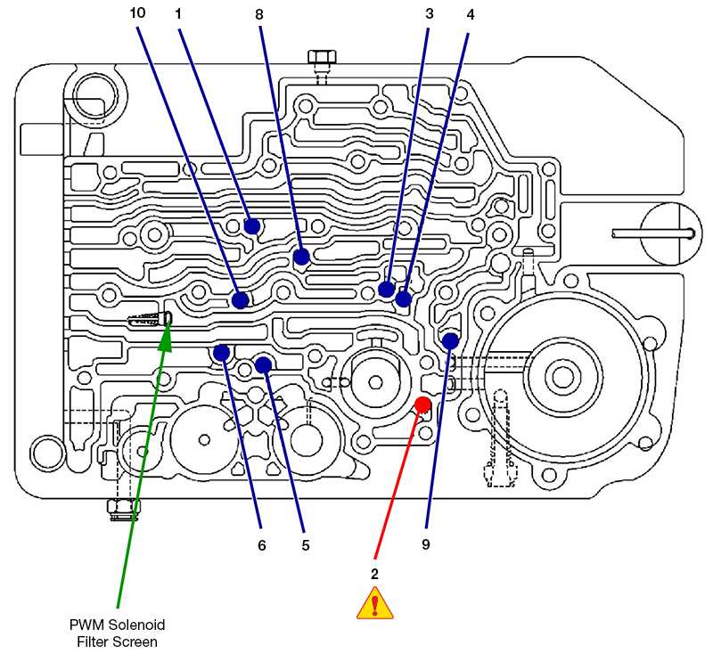
The reconstruction of a specific vehicle component is a detailed and meticulous task that requires careful planning and execution. This process involves disassembling the unit, inspecting each element for wear or damage, and replacing or refurbishing components as necessary. Proper techniques and attention to detail are essential to ensure optimal performance and longevity of the assembly.
Initially, the entire assembly is carefully taken apart, allowing for a thorough examination of all internal components. Identifying any signs of wear, such as scoring or pitting, is crucial during this stage. Once inspected, each piece is cleaned to remove any debris or residue that could affect functionality. After this, new or refurbished components are selected to replace those that do not meet specifications.
Following the replacement of worn items, reassembly begins. It is vital to adhere to the manufacturer’s guidelines to guarantee that everything fits together correctly and functions as intended. Proper alignment and torque specifications must be maintained throughout the process to prevent future issues.