Understanding the various components of lawn care machinery is essential for efficient maintenance and operation. Each piece has a unique function, contributing to the overall performance and longevity of the device. Ensuring that all elements work together seamlessly allows for optimal results and reduces the risk of mechanical issues.
In this guide, we will delve into the key elements that make up typical outdoor equipment, focusing on how these components interact and why regular inspection and care are crucial. From small mechanisms to larger structural parts, gaining insight into these elements will help you maintain your equipment in top condition.
By learning about individual elements, you’ll not only enhance your understanding of the machine but also become better equipped to troubleshoot potential issues. A detailed look at these components will empower you to carry out basic repairs and upkeep with greater confidence.
Echo SRM 210 Trimmer Parts Overview
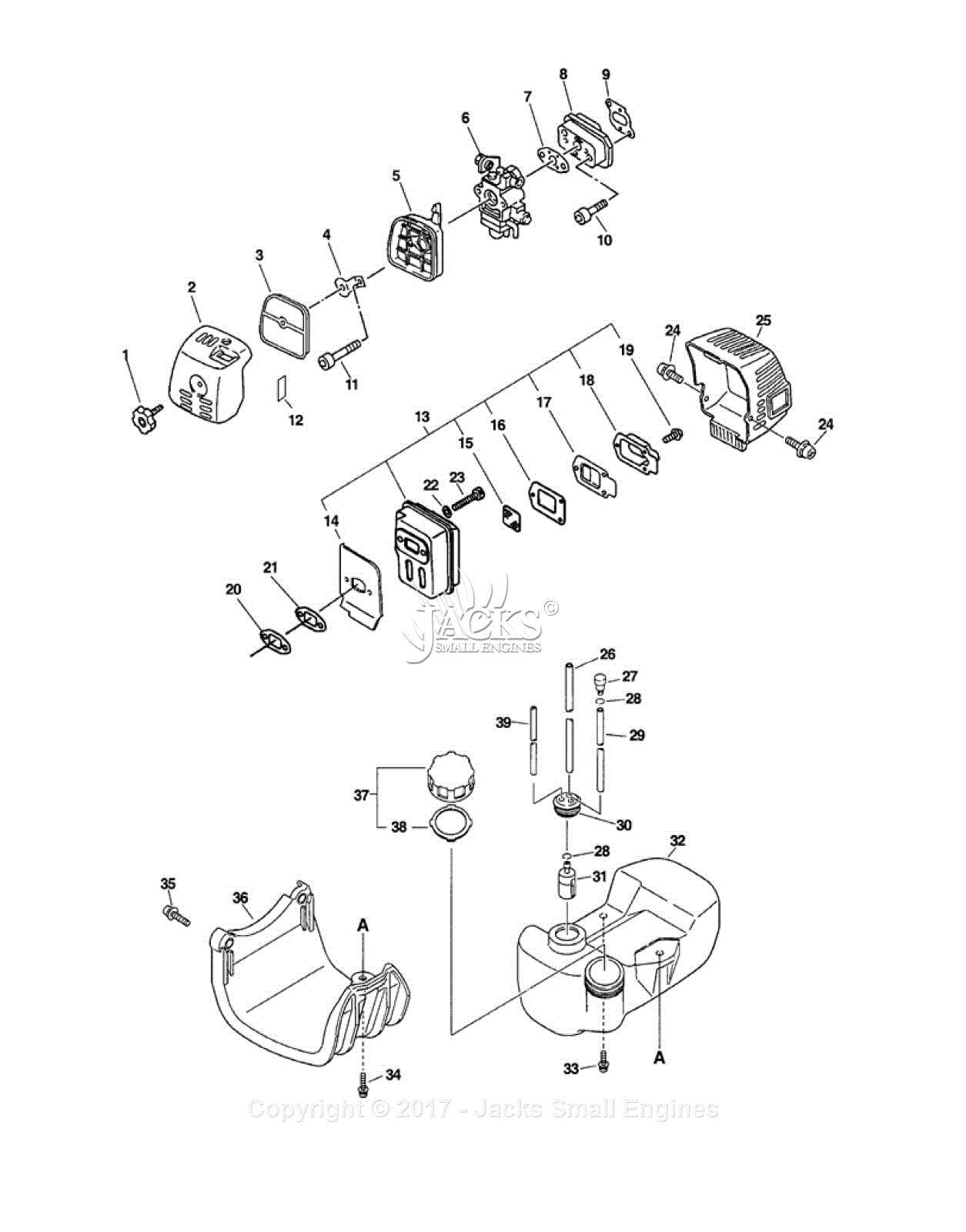
The components of this specific garden tool model are designed to ensure efficient performance and durability. Understanding the key elements of its construction helps in maintaining its functionality and replacing worn-out parts when necessary. In this section, we’ll explore the essential sections and pieces that make up the device, giving you insight into its structure.
| Component | Description | ||||||||||||||||||||||||||||||
|---|---|---|---|---|---|---|---|---|---|---|---|---|---|---|---|---|---|---|---|---|---|---|---|---|---|---|---|---|---|---|---|
| Power Head | Houses the engine, ensuring the necessary power output for the tool. | ||||||||||||||||||||||||||||||
| Driveshaft | Transfers energy from the engine to the cutting head, facilitating motion. | ||||||||||||||||||||||||||||||
| Component | Function | ||||||||||||||||||||||
|---|---|---|---|---|---|---|---|---|---|---|---|---|---|---|---|---|---|---|---|---|---|---|---|
| Carburetor | Mixes air and fuel for combustion. | ||||||||||||||||||||||
| Cylinder | Contains the piston and is the chamber where combustion occurs. | ||||||||||||||||||||||
| Spark Plug | Ignites the fuel-air mixture to initiate combustion. | ||||||||||||||||||||||
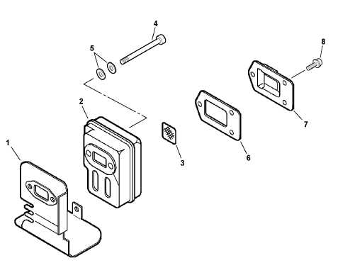
| Muffler | Reduces
Fuel System and Carburetor Details
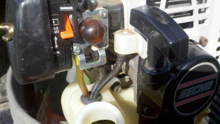
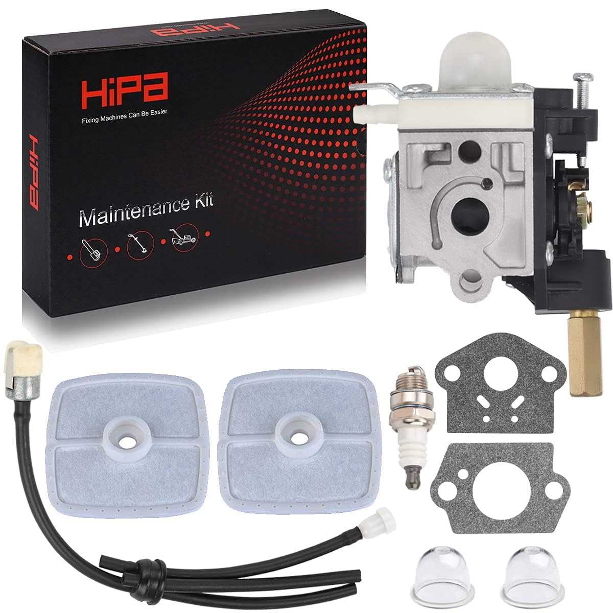
The fuel system and carburetor are essential components that ensure smooth operation and efficient performance. They regulate the flow of fuel and air mixture into the engine, maintaining optimal combustion. Understanding these systems is crucial for troubleshooting and maintaining peak performance. Key Functions of the Fuel System
The fuel system is responsible for storing, filtering, and delivering fuel to the carburetor. Proper fuel flow is vital for consistent engine performance, and any blockages or leaks can disrupt the process, leading to potential issues like stalling or inefficient power output. Carburetor Adjustments and MaintenanceThe carburetor mixes fuel and air in the right proportions for combustion. Regular adjustments and cleaning are necessary to keep the system functioning correctly. Over time, debris can accumulate Cutting Head Assembly Breakdown
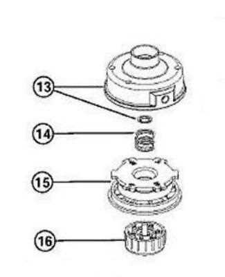
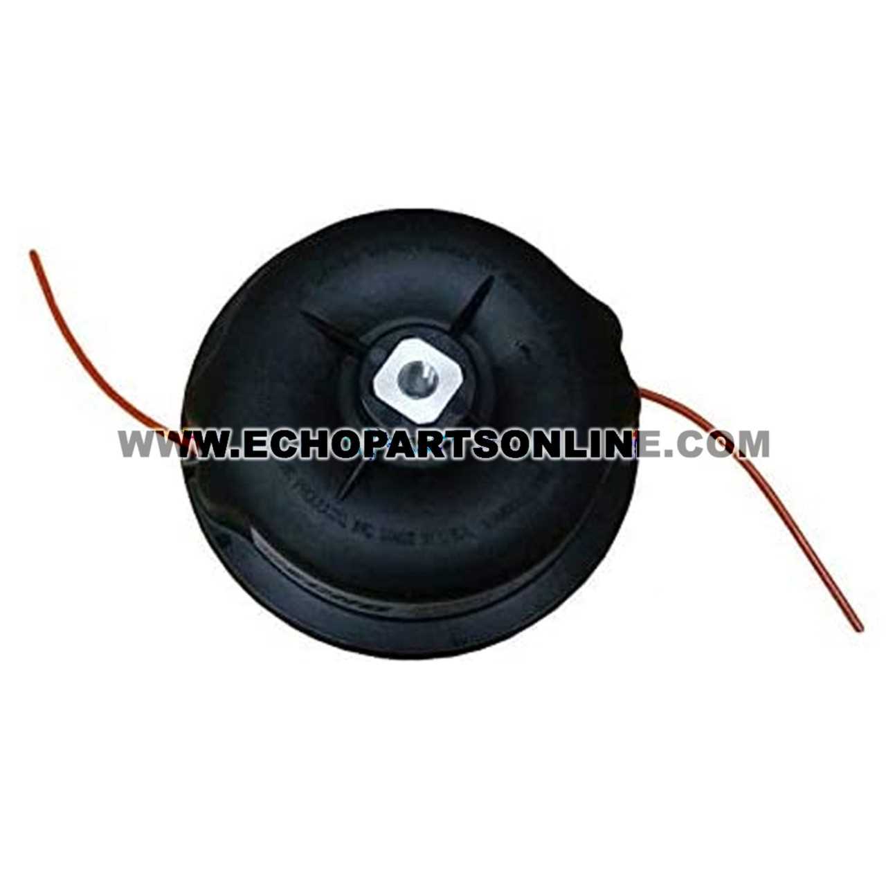
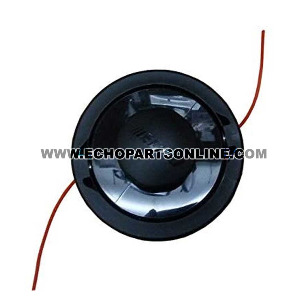
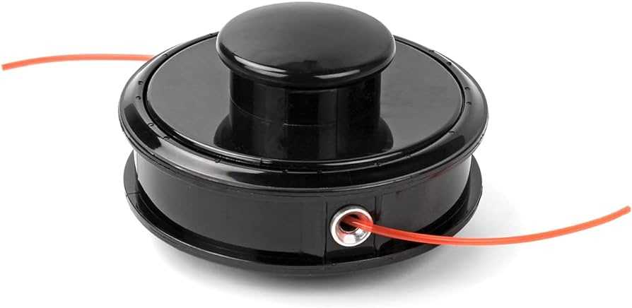
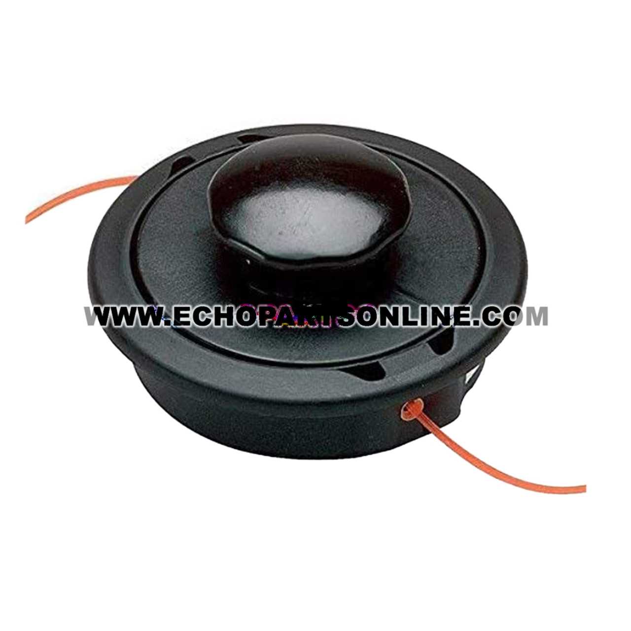
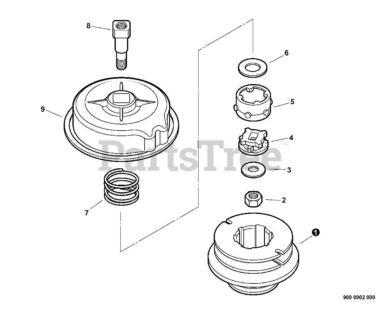
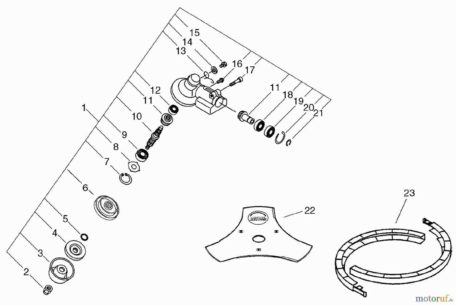
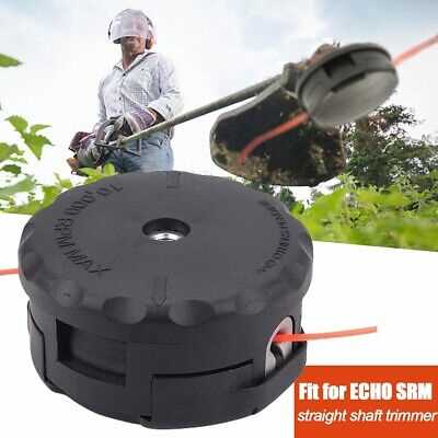
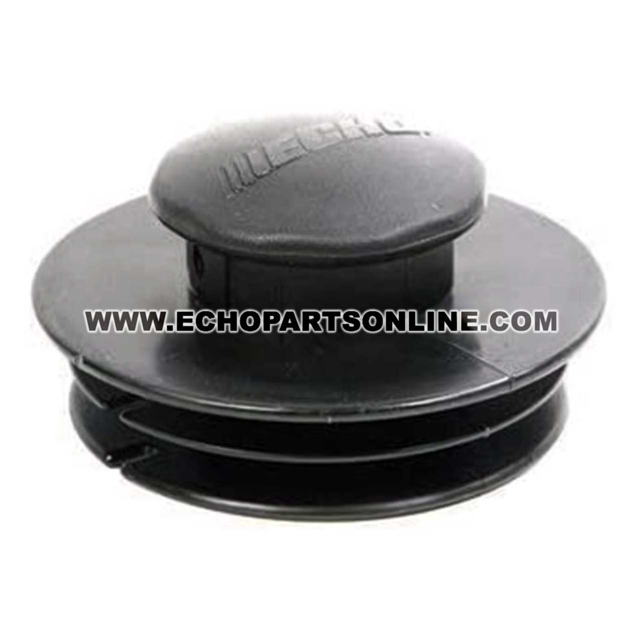
The cutting head assembly consists of several key components that work together to ensure efficient cutting performance. Understanding how each part functions and interacts is essential for maintaining optimal operation. This section will provide a detailed overview of the assembly, focusing on the most important elements involved in the process. Main Components
The primary elements of the cutting head include a central hub, rotating mechanisms, and line holders. Each piece has a specific role in ensuring that the cutting line remains stable and performs at its best during use. Maintenance and Replacement
Regular maintenance of the cutting head components is crucial to prolong the lifespan of the assembly. Periodic inspections and timely replacements of worn or damaged elements can prevent larger issues from arising. Always ensure the proper alignment of each part during reassembly to maintain smooth functionality. Throttle and Control Mechanism
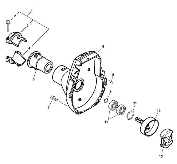
The throttle and control mechanism is a vital component of outdoor power equipment, enabling precise regulation of engine performance. This system allows users to manage the speed and power output of the machine efficiently, ensuring optimal operation during various tasks. At the core of this mechanism is the throttle control, which typically consists of a lever or trigger that users manipulate to adjust the engine’s RPM. This feature enhances user experience by providing responsive control over the equipment’s speed, catering to different working conditions. Additionally, the control mechanism often integrates safety features that prevent accidental activation, thereby improving overall safety during operation. Understanding the functionality and maintenance of this system is essential for ensuring longevity and efficiency, ultimately leading to better performance in landscaping and gardening tasks. Drive Shaft and Gearbox StructureThe drive shaft and gearbox are crucial components in the operation of a handheld power tool. They work in unison to transfer energy from the engine to the cutting mechanism, ensuring efficient performance and optimal functionality. Understanding the intricacies of these elements can enhance maintenance practices and improve the overall lifespan of the equipment. Drive Shaft Functionality
The drive shaft serves as a conduit for rotational energy generated by the engine. It is designed to withstand significant torque while maintaining stability under varying operational conditions. This component is typically constructed from robust materials to minimize wear and enhance durability, ultimately contributing to the reliability of the tool. Gearbox Design and ImportanceThe gearbox plays a pivotal role in adjusting the speed and torque of the rotational output. It consists of various gears and bearings that facilitate smooth operation and adaptability to different cutting tasks. The design of the gearbox ensures that the power tool can handle demanding applications while optimizing performance, making it an essential aspect of the overall machinery. Ignition System Parts and FunctionThe ignition system is a crucial component of any internal combustion engine, responsible for igniting the fuel-air mixture within the combustion chamber. This process initiates the engine’s operation, ensuring smooth performance and efficiency. Understanding the various elements of this system and their specific functions is essential for effective maintenance and troubleshooting. Key Components of the Ignition System
Importance of the Ignition System
A properly functioning ignition system is vital for engine performance. It ensures efficient fuel combustion, which not only improves power output but also reduces emissions. Regular checks and maintenance of the ignition components can prevent potential issues, leading to enhanced reliability and longevity of the engine. Air Filter Housing and Maintenance
The air filter housing plays a crucial role in ensuring optimal engine performance by preventing dust and debris from entering the engine. Regular maintenance of this component is essential to prolong the lifespan of your equipment and maintain its efficiency. Importance of the Air Filter
Maintaining a clean air filter is vital for proper airflow and engine function. A clogged filter can lead to reduced performance, increased fuel consumption, and potential engine damage. Regular inspection and cleaning can significantly enhance the machine’s efficiency. Maintenance TipsTo keep the air filter housing in good condition, follow these guidelines:
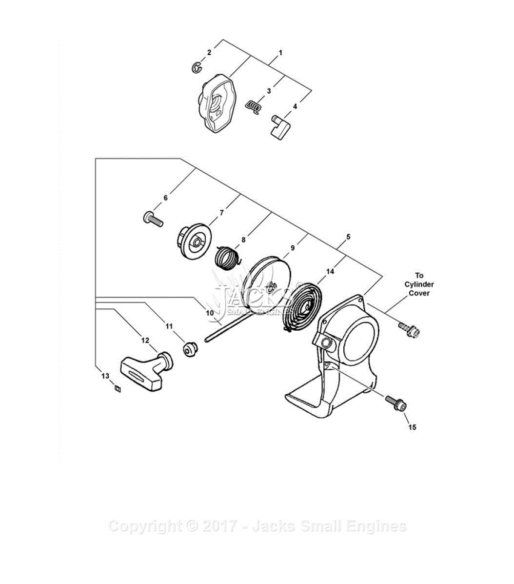
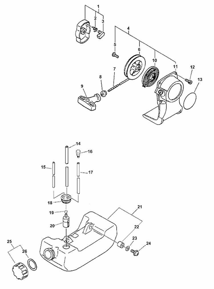
By following these maintenance practices, you can help ensure the longevity and effectiveness of your equipment. Recoil Starter and Pull Cord AssemblyThe recoil starter and pull cord assembly are crucial components of many handheld power equipment devices, enabling users to easily initiate engine operation. This mechanism provides a reliable method for starting the engine without the need for complex electrical systems. Understanding its structure and function can assist in troubleshooting and maintenance, ensuring optimal performance during use. Components of the Recoil Starter
Maintenance Tips
Handlebar and Safety Features Diagram
This section presents a comprehensive overview of the handlebar assembly and the associated safety components found in the equipment. Understanding these elements is crucial for ensuring optimal performance and user protection during operation.
|
