Exploring the intricacies of all-terrain vehicles reveals a complex web of elements that contribute to their performance and functionality. A thorough grasp of these components is essential for both maintenance and customization, allowing enthusiasts to enhance their riding experience and ensure longevity.
In this section, we will delve into the various features and structures that make up these robust machines. By examining the relationships between different components, one can better appreciate how each part interacts to deliver optimal performance in diverse conditions.
Whether you are a seasoned rider or a newcomer to the off-road scene, familiarizing yourself with the essential elements can empower you to make informed decisions regarding repairs and upgrades. This knowledge not only aids in troubleshooting but also enhances the overall enjoyment of the riding adventure.
Exploring Yamaha Kodiak Parts Diagram
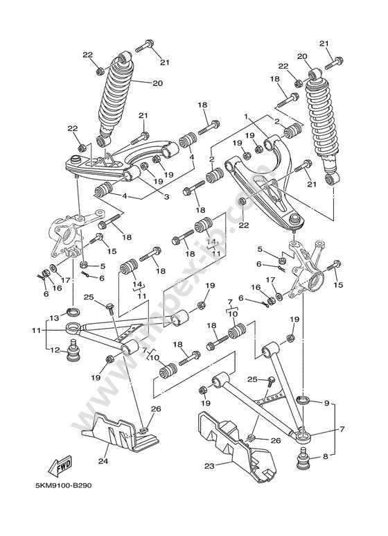
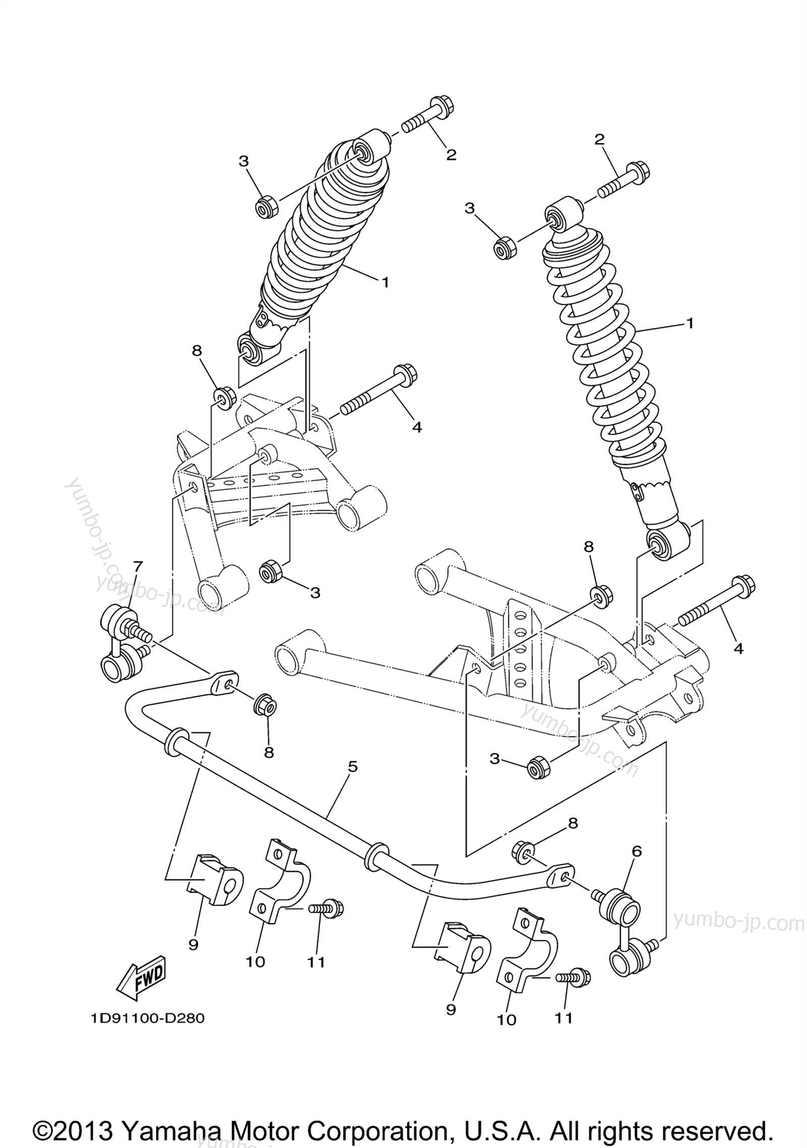
In this section, we delve into the intricate details of the component layout for the Yamaha Kodiak, uncovering the interconnected system of components that make up its functional framework. Our exploration focuses on dissecting the internal anatomy, highlighting the integral parts that contribute to its overall performance and reliability. Through a meticulous examination, we aim to provide a comprehensive understanding of how these elements synergistically operate, without directly referencing their specific nomenclature. Each piece plays a crucial role in sustaining the Kodiak’s operational integrity, ensuring optimal functionality across various terrains and conditions.
Understanding the Layout of Yamaha Kodiak Components

Grasping the arrangement of components within an all-terrain vehicle is essential for both maintenance and enhancement. A clear comprehension of how each element fits into the overall structure can significantly streamline repairs and modifications. This knowledge empowers users to identify specific sections and functionalities, thereby improving their interaction with the vehicle.
Each section of the vehicle serves a distinct purpose, contributing to the overall performance and reliability. Familiarizing oneself with these various components can facilitate better decision-making during troubleshooting or upgrades. For instance, recognizing the placement of the engine, transmission, and suspension elements is vital for effective diagnostics and repair.
Additionally, understanding the interconnectedness of these parts enhances the ability to optimize performance. By knowing how each component interacts with others, one can make informed adjustments, ensuring the vehicle operates at its best. Ultimately, this knowledge not only fosters a deeper connection with the machine but also promotes its longevity and efficiency.
Key Components in the Yamaha Kodiak Parts Diagram
Understanding the essential elements of a vehicle’s structure is crucial for effective maintenance and repair. A clear representation of these components helps enthusiasts and technicians alike to identify and locate each part efficiently. This section delves into the fundamental sections found within the schematic, emphasizing their significance in the overall functionality of the machine.
Core Elements
The main constituents often include the engine assembly, transmission system, and suspension framework. Each of these parts plays a vital role in ensuring optimal performance. For instance, the engine assembly serves as the powerhouse, driving the vehicle’s capabilities. Meanwhile, the transmission system facilitates smooth gear shifts, contributing to the overall driving experience.
Additional Features

In addition to the primary assemblies, various auxiliary components like the braking system and electrical units are illustrated. These elements are equally important, as they enhance safety and control. The braking system, for example, ensures reliable stopping power, while the electrical units power essential accessories and instrumentation. Recognizing these features aids in troubleshooting and ensures the longevity of the vehicle.
Interpreting Symbols and Icons in the Diagram
Understanding the various symbols and icons within a technical schematic is crucial for proper maintenance and troubleshooting. These visual markers provide key information about different components, helping to identify connections, functions, and potential issues. By familiarizing yourself with these graphical cues, you can efficiently navigate through the schematic without confusion.
The symbols in such diagrams often represent mechanical and electrical elements, guiding the viewer on how to interpret the layout of components and their interactions. Below is a table detailing common icons and their meanings, allowing you to decode the schematic with ease.
| Icon |
Meaning |
| ⚡ |
Electrical connection or power source |
| ⚙️ |
Common Maintenance Tips Derived from the Diagram
Understanding the layout of key components in your vehicle can simplify routine upkeep. The visual guide provides essential insights into the location and interaction of various mechanical elements, helping to maintain optimal performance and prevent future issues.
Lubrication and Fluid Checks

- Regularly inspect lubrication points to ensure all moving parts are properly oiled.
- Check fluid levels, such as engine oil and coolant, to avoid overheating or unnecessary wear.
- Replace fluids at the recommended intervals to prolong the life of mechanical components.
Inspection of Wear-Prone Areas
Many components are subject to wear and tear over time. Consistently reviewing these areas based on their position in the system helps in early detection of issues.
-
Exploring Electrical Connections in the Yamaha Kodiak
Understanding the electrical system is crucial for maintaining smooth operation and performance. The wiring harness, switches, and other electronic components work together to ensure all systems function properly. By examining the connections, you can identify potential issues, prevent malfunctions, and optimize overall efficiency.
Key Components of the Electrical System
The electrical system is composed of several vital parts that manage the flow of electricity. These include the main fuse box, ignition switch, and the various sensors spread throughout. Each component plays a specific role in maintaining functionality, ensuring that electrical power is properly distributed across different systems.
Wiring and Connector Overview
Wires and connectors serve as the backbone of the entire system, linking sensors and actuators with control units. Regular inspection of these elements is important to avoid wear and corrosion, which could lead to electrical failures. Proper handling of connectors during maintenance is essential to avoid damage and ensure a long-lasting connection.
| Component |
Function |
Identifying Engine Parts in the Diagram
Understanding the layout of the engine components in a visual guide is crucial for maintaining and repairing your vehicle. Each element plays a specific role in the overall function, and recognizing them can simplify troubleshooting and ensure accurate repairs.
One of the most essential elements is the cylinder head, which houses important mechanisms like the valves and spark plug. Directly beneath it is the cylinder block, the core structure that houses the combustion chambers and pistons. Proper identification of these areas can help locate issues such as misfiring or compression loss.
Additionally, the crankshaft and connecting rods are integral in converting the pistons’ up-and-down motion into rotational force. Recognizing these components in the guide ensures that issues related to power delivery can be diagnosed efficiently.
Finally, make
Using the Diagram for DIY Repairs
Repairing your vehicle on your own can be a rewarding experience, especially when you have access to a detailed visual guide. By understanding the layout and components of your machine, you can confidently tackle maintenance and replacements without needing professional help. A comprehensive illustration helps identify key elements and ensures you follow the correct steps during the repair process.
Benefits of Following a Visual Guide
A well-organized schematic allows you to locate specific sections of your vehicle with ease. This is particularly useful when dealing with complex systems that require precision. With a clear visual representation, you reduce the chances of making errors, saving both time and money. The ability to reference specific connections and assemblies ensures that even tricky repairs are handled with confidence.
Step-by-Step Approach to Maintenance

Before starting any repair, it’s essential to study the diagram and understand the connections between different elements. By
Comparing Different Models Through Their Parts Diagrams
Understanding the unique construction of various models can provide valuable insight when maintaining or upgrading mechanical systems. By analyzing their detailed schematics, it’s possible to observe how individual components are arranged and interact, offering a clear perspective on the differences between each version. This approach helps identify key variations that affect performance, durability, and compatibility with additional accessories or replacements.
Key Differences in Component Placement
Examining the layout of internal mechanisms reveals distinct variations in how components are positioned. Some versions may have more compact designs, optimizing space usage, while others prioritize accessibility for easier maintenance. These differences can directly influence how a machine functions under various conditions, making it essential to compare these aspects when choosing between different models.
Practical Applications of the Yamaha Kodiak Parts Diagram
Understanding the detailed schematics of complex equipment is crucial for maintenance, repairs, and customization. These visual guides offer insights into the structure and arrangement of individual components, helping users identify key elements and their interconnections. By leveraging this resource, owners and technicians can efficiently troubleshoot issues, replace worn-out elements, and enhance performance.
One practical benefit of using such a resource is the ability to streamline the repair process. Clear visualization of all components ensures that technicians can quickly identify problem areas and carry out repairs without unnecessary disassembly. This helps reduce downtime and ensures that the equipment is operational in a shorter timeframe.
Additionally, these schematics are invaluable for sourcing compatible components. By referencing the visual guide, users ca
Resources for Accessing and Understanding the Diagram
To effectively maintain and repair various equipment, it is essential to have access to visual guides and detailed schematics. These resources allow users to easily identify components, understand their placement, and follow step-by-step processes for assembly or replacement. Whether for troubleshooting or upgrades, having the right materials can simplify the work significantly.
Where to Find Relevant Visual Guides
Numerous online platforms provide comprehensive diagrams that cover different models and configurations. From specialized websites to manufacturer support pages, users can locate schematics designed to match specific models. In addition, some third-party providers offer downloadable files, making it easy to store and access the information offline.
How to Read and Interpret the Schematic
Understanding the technical drawings can sometimes be a challenge, especially for those new to maintenance work. Key aspects to focus on include recognizing component labels, identifying symbols, and following


