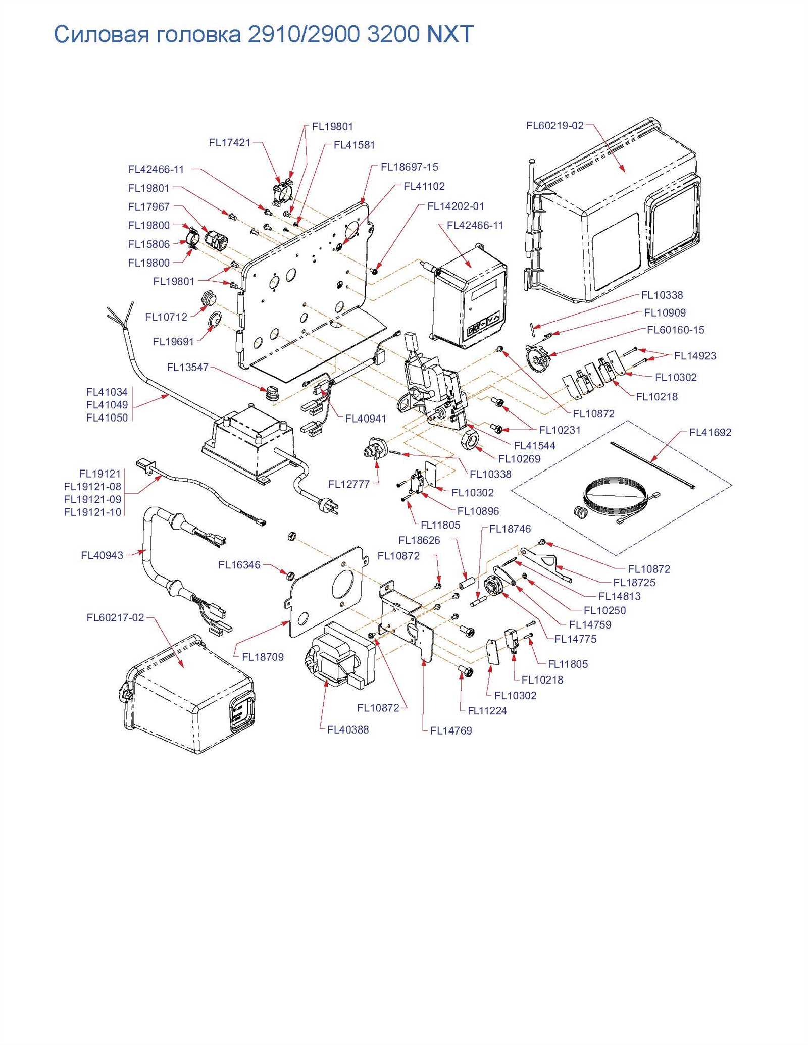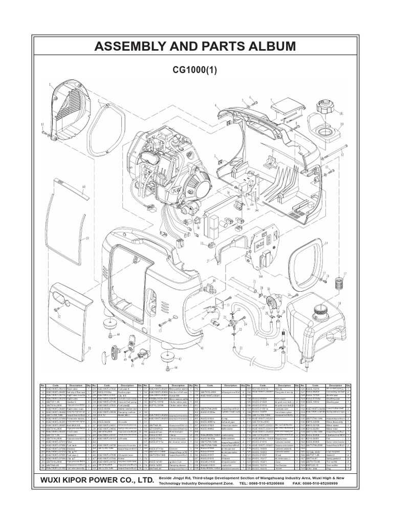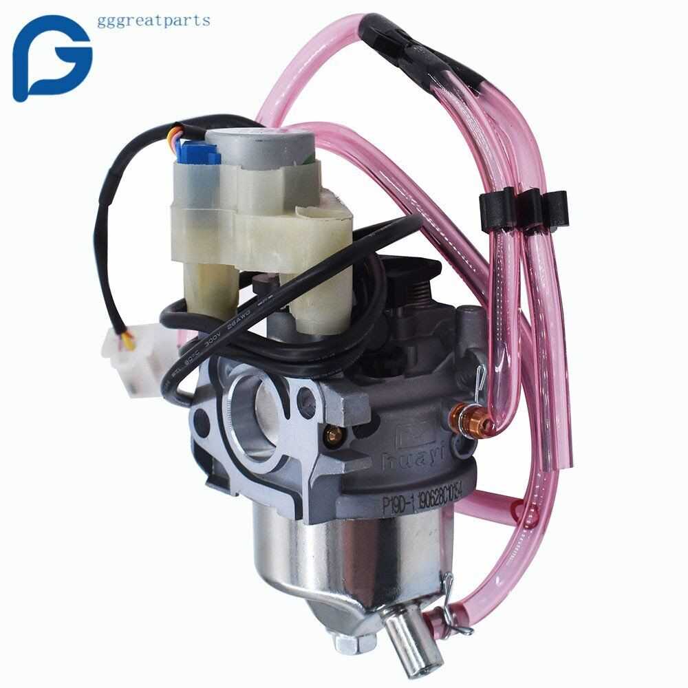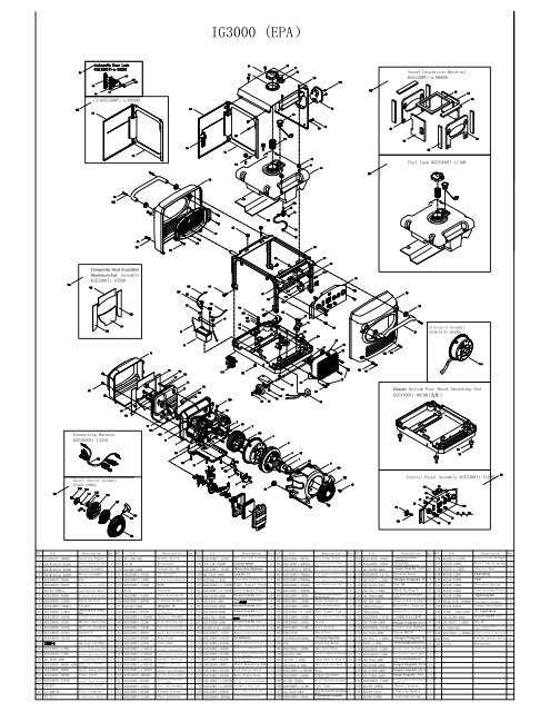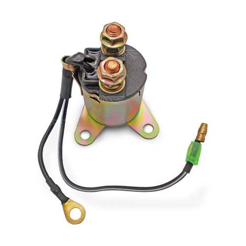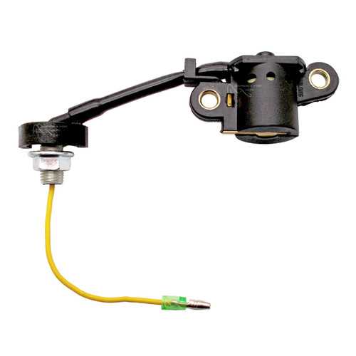
Understanding how portable generators are constructed is crucial for ensuring their proper maintenance and repair. Each element within these devices plays a significant role in delivering consistent energy output. In this section, we will examine the internal structure and key components of such equipment, shedding light on how they function together to create reliable power solutions.
The breakdown of various sections of the generator provides insight into its mechanical and electrical systems. These systems include various critical elements, each responsible for a specific task that ensures the generator runs efficiently. By gaining a deeper knowledge of these elements, one can maintain and troubleshoot issues more effectively, extending the life of the machine.
From the motor assembly to electrical connections, each component has a unique function, working in unison to power your essential devices. Whether you are performing routine maintenance or addressing a mechanical failure, knowing the inner workings of the equipment will provide invaluable support in handling the task at hand.
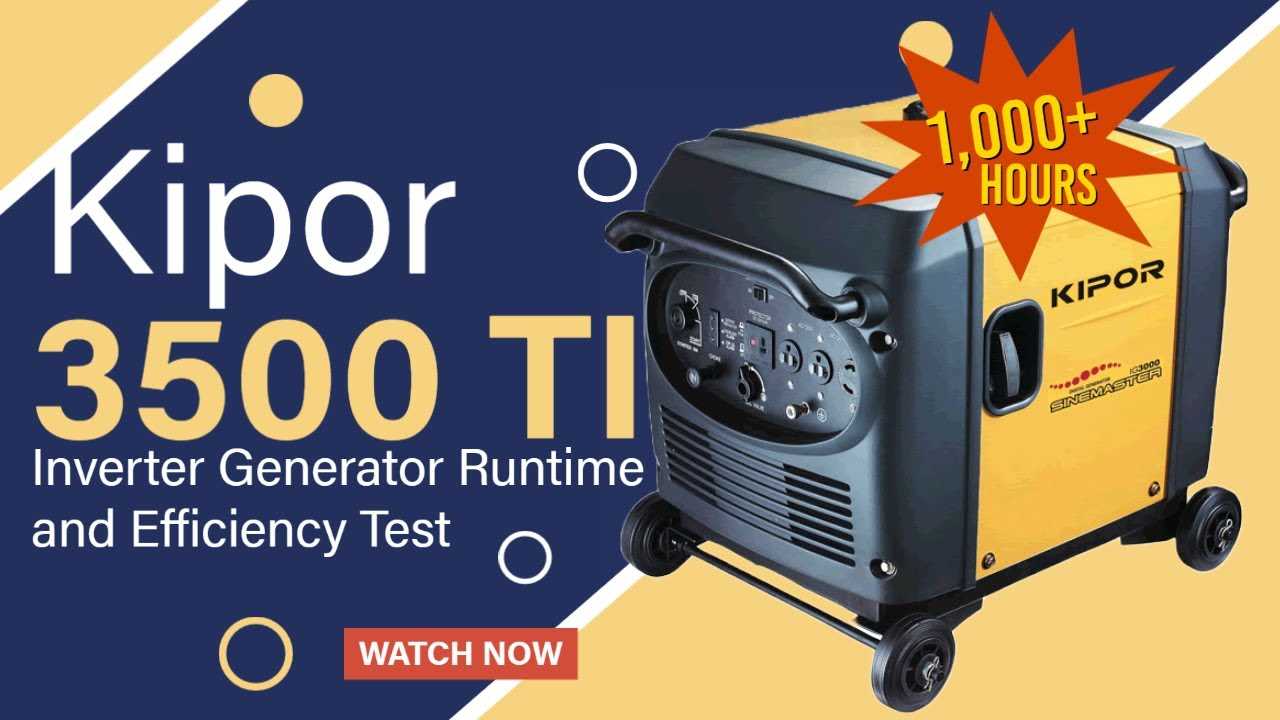
Overview of the Kipor KGE 3000 Ti Generator
This versatile power unit is designed to provide reliable electricity in various situations, whether for home use, outdoor activities, or work sites. Known for its efficiency and robust design, the machine ensures consistent performance while being relatively lightweight and easy to transport.
Its compact structure and advanced features make it a great choice for those needing a portable source of power. The device’s modern engine technology helps reduce fuel consumption, offering extended operating times without sacrificing power output.
| Feature | Description | ||||||||||||||||||||||||||
|---|---|---|---|---|---|---|---|---|---|---|---|---|---|---|---|---|---|---|---|---|---|---|---|---|---|---|---|
| Output Capacity | Provides a stable and high-quality energy supply for various electronic devices. | ||||||||||||||||||||||||||
| Fuel Efficiency |
| Component | Description | Function |
|---|---|---|
| Filter Media | A material that captures particles from the air | Removes dust, pollen, and other pollutants |
| Airflow Path | The route air takes through the filtration system | Ensures efficient passage of air while maximizing exposure to the filter media |
| Housing | A protective casing that encloses the filter | Prevents debris from entering and protects the filter from damage |
Incorporating these elements effectively can lead to a significant reduction in harmful emissions and improved overall system reliability. Regular maintenance and timely replacement of filter components are essential to sustain performance and achieve optimal results.
Alternator Components and Maintenance
The alternator is a vital component of the electrical system in many engines, responsible for converting mechanical energy into electrical energy. Understanding its parts and maintenance requirements is crucial for ensuring optimal performance and longevity.
Key Components of the Alternator
- Stator: The stationary part of the alternator that generates electricity when the rotor spins.
- Rotor: A rotating element that creates a magnetic field, essential for generating current.
- Rectifier: Converts alternating current (AC) produced by the stator into direct current (DC) for the battery and electrical systems.
- Voltage Regulator: Maintains the output voltage within a specified range, protecting the electrical components from damage.
- Bearings: Support the rotor and allow it to spin smoothly, reducing friction and wear.
Maintenance Tips
- Regularly inspect electrical connections for corrosion or damage, ensuring a solid connection.
- Check the belt tension and condition to avoid slipping, which can affect performance.
- Clean the alternator exterior to prevent dust and debris accumulation that may hinder cooling.
- Test the output voltage periodically with a multimeter to ensure it meets specifications.
- Replace worn bearings and any damaged components promptly to avoid failure.
Control Panel Layout Explanation
The arrangement of the control interface plays a crucial role in the operation and user experience of a generator. Understanding the layout allows users to effectively manage the unit’s functions and monitor its performance. Each section of the control panel is designed with specific purposes in mind, facilitating easy access to essential controls and indicators.
The interface typically features a combination of switches, dials, and displays that inform the operator about the generator’s status. Common elements include the power switch, which initiates the unit, and various gauges that provide readings for voltage, current, and fuel levels. Additionally, there are often warning lights that signal potential issues, ensuring the user can respond promptly to any anomalies.
Moreover, the design of the control panel is oriented towards user-friendliness, with clearly labeled components that guide operation. This layout not only enhances the efficiency of use but also promotes safety by minimizing the likelihood of operational errors. An intuitive arrangement ensures that even less experienced users can navigate the functions with confidence.
In summary, the control panel’s configuration is a fundamental aspect of generator functionality, providing operators with the tools necessary for effective management and monitoring. Familiarity with this layout empowers users to maximize performance while maintaining safety and reliability.
Recoil Starter Mechanism Breakdown
The recoil starter system is a critical component in portable engines, facilitating the initial crank of the motor. This mechanism employs a series of interconnected parts that work in harmony to ensure reliable operation. Understanding how this assembly functions is essential for effective maintenance and troubleshooting.
The primary element in this mechanism is the spring, which stores energy when the starter handle is pulled. As the handle is released, the spring unwinds, engaging the pawls that grip the engine’s flywheel. This engagement initiates the engine’s rotation, allowing it to start. Proper tension and alignment of the spring are crucial for optimal performance.
Additionally, the starter cord plays a vital role in the operation. It must be durable enough to withstand repeated pulls yet flexible enough to return smoothly to its original position. Regular checks for wear and tear can prevent unexpected failures during use.
Lastly, understanding the housing that encases these components is important. It protects the internal parts from debris and damage while ensuring that the recoil system operates smoothly. Any cracks or misalignments in the housing can lead to significant performance issues, emphasizing the need for routine inspections.
Frame and Mounting Details
The structural components and assembly specifications of any generator play a crucial role in its overall functionality and durability. This section provides an overview of the essential features related to the framework and installation requirements of a specific generator model, emphasizing stability and performance.
Structural Components
- Chassis: The base structure designed to support the entire unit, ensuring it remains stable during operation.
- Mounting Brackets: Essential for securing the generator to the foundation, preventing vibrations and movement.
- Foot Pads: Designed to absorb shocks and provide additional stability, these elements help maintain the unit’s position.
- Enclosure Frame: Protects internal components from environmental factors while allowing for proper ventilation.
Installation Considerations
- Ensure a flat, level surface for installation to avoid undue stress on the structural elements.
- Verify that all mounting hardware is secured tightly to maintain stability during operation.
- Consider accessibility for maintenance, ensuring that components are reachable without compromising the integrity of the installation.
- Adhere to any specified clearances from walls and other structures to allow for safe operation and maintenance.
Parts Replacement and Maintenance Tips
Ensuring the longevity and optimal performance of your generator requires regular upkeep and timely component swaps. This section provides essential guidance for effectively managing maintenance tasks and replacing key elements to maintain reliability and efficiency.
Regular inspection is crucial for identifying wear and tear. Create a routine schedule to check all significant components, including the engine, fuel system, and electrical parts. Address any signs of damage or degradation immediately to prevent further issues.
| Component | Replacement Frequency | Maintenance Tip |
|---|---|---|
| Oil Filter | Every 100 hours of operation | Always use a high-quality filter to ensure optimal performance. |
| Air Filter | Every 50 hours of operation | Clean or replace regularly to prevent dirt from entering the engine. |
| Spark Plug | Every 200 hours of operation | Check for wear and replace as needed for efficient ignition. |
| Fuel Filter | Every 100 hours of operation | Replace to ensure clean fuel reaches the engine, enhancing performance. |
Keep a detailed log of all maintenance activities and component changes. This practice will help track the operational history and predict future service needs. Following these guidelines will not only extend the life of your generator but also ensure it operates at peak efficiency.
