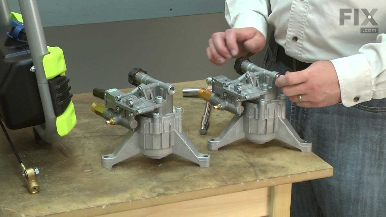
Understanding the organization and interconnection of various elements within a machine is essential for maintaining its functionality. Each element serves a specific purpose, working in harmony with others to ensure smooth operation. Having a clear visual representation of these components can significantly aid in diagnosing issues and performing repairs.
To keep your equipment running efficiently, it’s crucial to become familiar with the layout and the positioning of essential elements. This knowledge enables quick identification of problem areas, helping to streamline the troubleshooting process. Regular checks and awareness of how each component fits into the overall mechanism can extend the life of your machine.
Identifying and understanding the various components within your device provides a comprehensive view of its design. Recognizing their placement and function will make maintenance tasks more manageable, allowing for timely replacements or repairs when necessary.
Overview of Key Components
The essential elements of this equipment work together to ensure smooth operation and efficiency. Each section contributes a specific function, ensuring optimal performance and durability. Understanding the structure and main elements is crucial for both maintenance and repair tasks.
Main Framework and Structural Support

The primary framework offers a solid foundation, providing stability and balance during use. It is designed to withstand various conditions and ensures that all other elements are securely attached. This base is essential for maintaining the machine’s integrity over time.
Engine and Power Transmission

The engine drives the overall performance, delivering the necessary force to operate the equipment effectively. Power transmission components ensure that energy flows efficiently from the engine to other working elements, minimizing losses and maximizing output.
Engine Assembly Breakdown
The engine assembly consists of multiple interconnected components that work together to ensure smooth operation. Understanding the layout and function of each component is essential for maintenance and troubleshooting. Below is a detailed breakdown of the engine’s primary elements.
- Crankshaft: Converts linear motion into rotational energy, driving the machine’s main functions.
- Pistons: Move up and down within cylinders, generating the force required for rotation.
- Cylinder Head: Houses the valves and spark plug, managing airflow and combustion within the engine.
- Camshaft: Controls the opening and closing of the intake and exhaust valves in sync with piston movement.
- Valve System: Regulates the intake of fuel and air, as well as the release of exhaust gases.
- Ensure regular inspection of the crankshaft for signs of wear.
Fuel System Layout
The fuel system ensures the proper delivery of fuel to the engine, allowing for efficient combustion and performance. It is designed to manage fuel storage, transfer, and filtration before the engine can utilize it. Each component plays a critical role in maintaining steady fuel flow and ensuring the engine operates smoothly.
Fuel Tank and Transfer
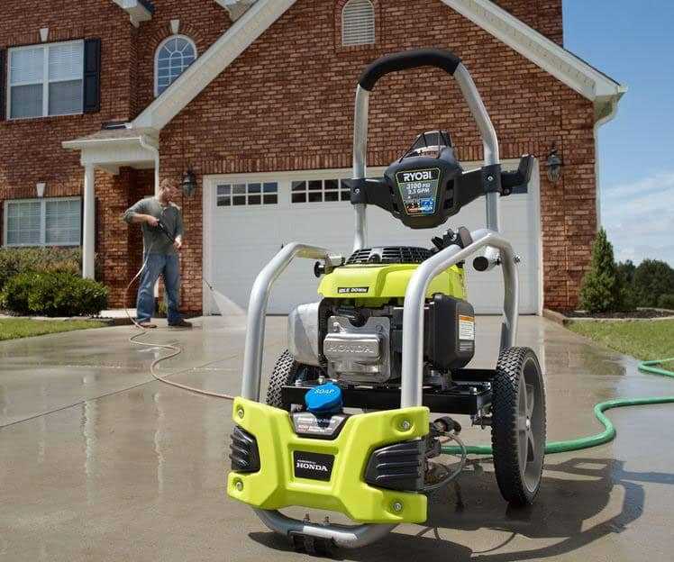
The system begins with the fuel tank, which stores the fuel until it is needed. From there, the fuel pump moves it through the lines towards the engine. The pump ensures consistent pressure, so the fuel reaches its destination without interruption.
Filtration and Injection

Before the fuel reaches the engine, it passes through filters to remove impurities. Clean fuel then travels to the injectors, where it is precisely distributed into the engine’s combustion chamber, enabling optimal performance and energy efficiency.
Exhaust Mechanism Configuration
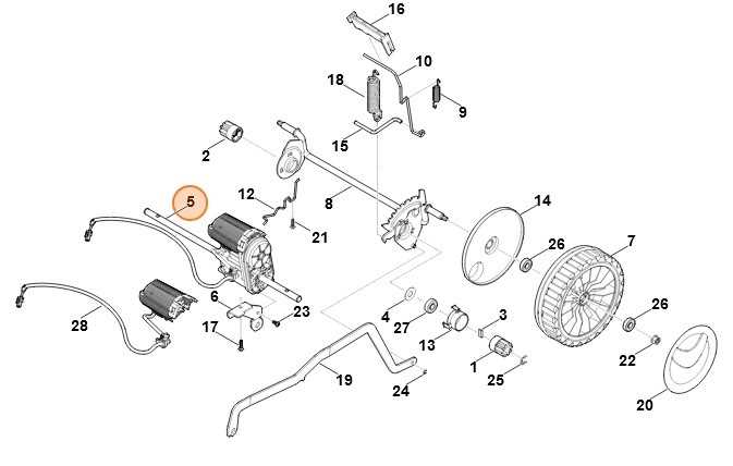
The exhaust system is designed to effectively manage the release of gases generated during engine operation. This process helps maintain optimal performance by ensuring the removal of emissions without causing obstructions or backpressure that could affect the engine’s functionality. An efficient exhaust setup plays a key role in enhancing overall machine efficiency.
Main Components of the Exhaust System
Key elements involved in the exhaust structure include the manifold, which gathers gases from multiple points, and the muffler, which minimizes noise levels during gas expulsion. These parts work in harmony to create a balanced flow, ensuring minimal impact on the engine’s operational dynamics.
Optimizing Exhaust Flow
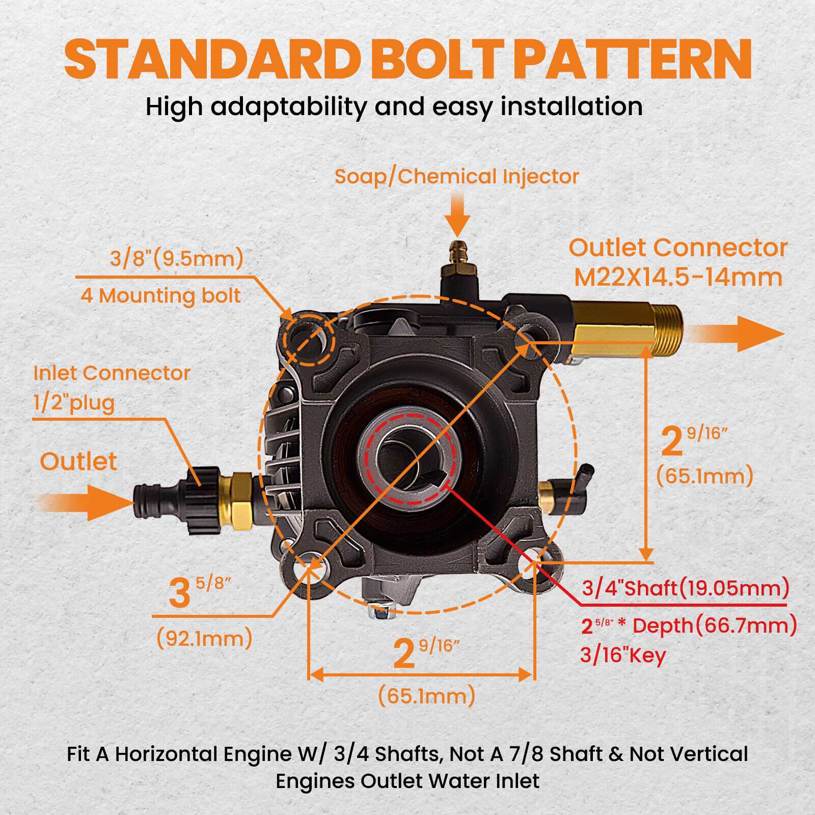
Adjusting the exhaust flow is crucial for maximizing efficiency. The design and placement of components must support smooth airflow to reduce resistance. Properly configured exhaust pathways enhance both engine longevity and fuel consumption, creating a balanced
Power Transmission Components
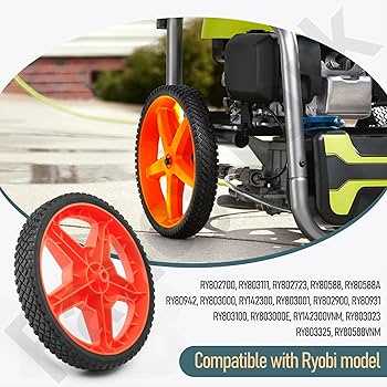
Power transmission systems rely on various elements to efficiently transfer mechanical energy from the source to the desired machinery. These components ensure smooth operation and effective energy distribution, playing a critical role in the overall performance of mechanical systems.
- Drive Belts: Flexible belts that transfer power between pulleys, ensuring smooth operation of connected devices.
- Gears: Interlocking teeth used to alter torque and speed ratios between rotating shafts.
- Shafts: Rotating elements that carry torque between different parts of the system, providing structural support.
- Couplings: Devices that connect two shafts together, allowing for flexibility and alignment adjustment.
- Bearings:
Electrical Wiring Overview
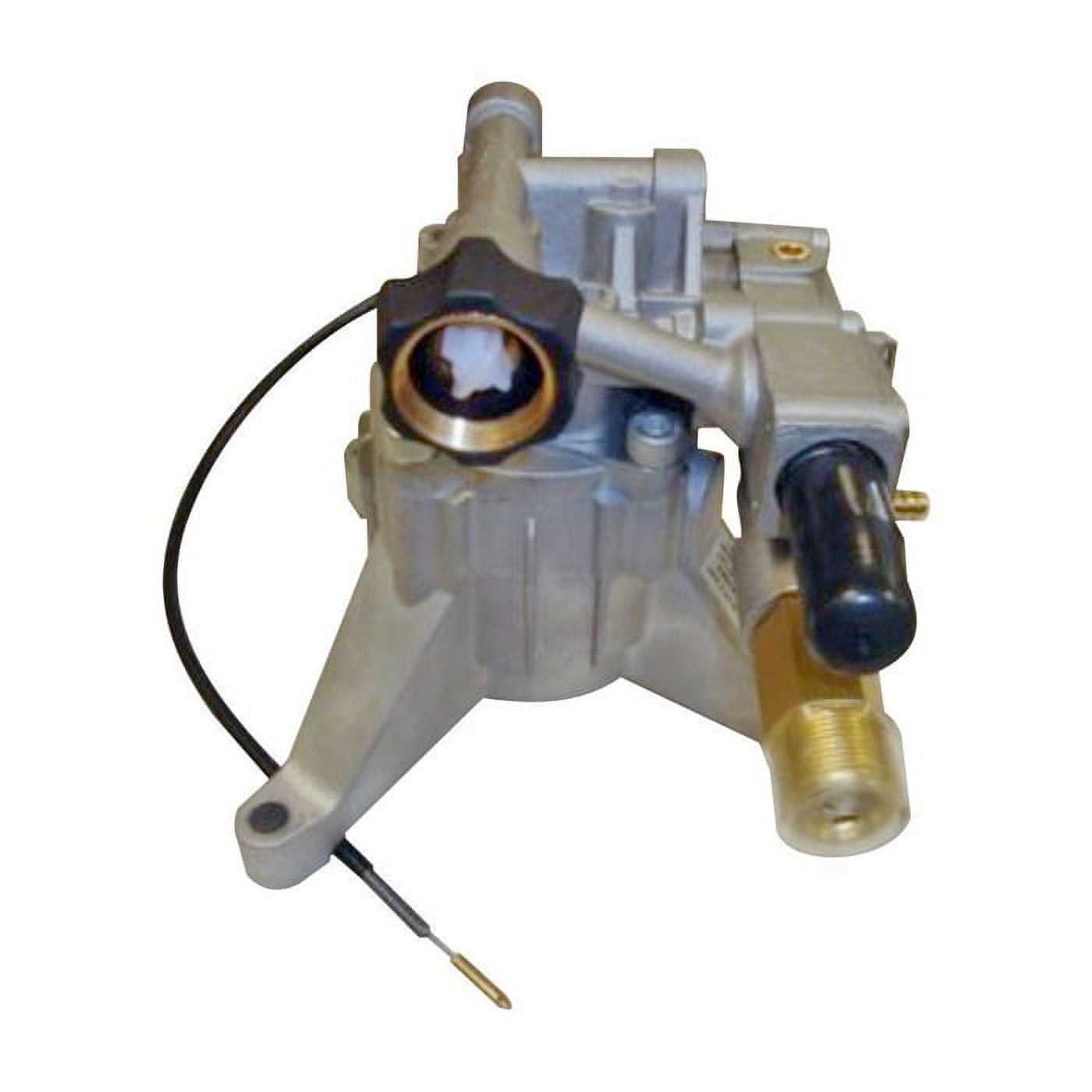
This section provides a comprehensive understanding of the electrical connections necessary for the device’s operation. Proper wiring is crucial for ensuring efficiency and safety in functionality.
Component Description Function Power Supply Source of electrical energy Delivers power to the system Connectors Interfaces for linking wires Facilitate secure connections Wiring Harness Bundle of wires organized together Streamlines connections between components Grounding System Path for electrical discharge Enhances safety and prevents malfunctions Pump and Valve Setup

Proper configuration of the pumping and valve systems is crucial for optimal performance and efficiency. This setup ensures smooth operation and enhances the overall functionality of the machinery.
Components Overview
Understanding the key components involved in the setup is essential:
- Pump: Transports fluids within the system.
- Valves: Control the flow and pressure of the fluid.
- Connectors: Join various parts together securely.
- Filters: Remove impurities from the fluid.
Installation Steps
Follow these steps to achieve a successful installation:
- Ensure all components are compatible and clean.
- Install the pump at the designated location.
- Connect valves to the pump according to specifications.
- Secure all connections with appropriate fasteners.
- Test the setup for leaks and proper operation.
Frame Structure and Support
The framework of a device serves as its backbone, providing stability and rigidity. It is crucial for ensuring that all components remain securely in place, while also allowing for efficient performance. A well-designed frame can significantly enhance the overall functionality and longevity of the equipment.
Materials and Design
Choosing the right materials is essential in constructing a robust support system. Commonly used materials include steel, aluminum, and high-strength polymers, each offering unique benefits in terms of weight, strength, and resistance to environmental factors. The design must also consider the distribution of forces, ensuring that the structure can withstand various loads during operation.
Assembly and Maintenance

Proper assembly techniques are vital for achieving optimal performance. Ensuring that joints are secure and components are aligned will prevent premature wear and potential failures. Regular maintenance checks should also be implemented to identify any signs of wear or damage, allowing for timely repairs to maintain the integrity of the frame.
Pressure Washer Hose Design

The design of a pressure washer hose is crucial for optimal performance and efficiency. It plays a significant role in delivering water at high pressure while maintaining durability and flexibility. Understanding the various components and materials used in hose construction can enhance the overall cleaning experience.
- Material Composition: Hoses are often made from high-quality rubber or reinforced thermoplastic to withstand pressure and prevent kinks.
- Diameter: A larger diameter can facilitate a higher water flow rate, while a smaller diameter may increase pressure.
- Length: The length of the hose impacts maneuverability; longer hoses allow for greater reach but can lead to a drop in pressure.
- Connections: Quick-connect fittings ensure easy attachment and detachment from the pressure washer and spray gun.
- Reinforcement: Many hoses feature internal braiding or spirals for added strength, preventing bursts during operation.
Choosing the right design elements for a pressure washer hose can significantly improve cleaning efficiency and prolong the lifespan of the equipment.
Control Panel Parts
The control interface is essential for the efficient operation of the device, offering users a way to manage its functions and settings effectively. Understanding the various components within this section can enhance the overall user experience and ensure optimal performance.
- Display Screen: This element provides visual feedback on settings and status, allowing users to monitor operations at a glance.
- Buttons: Control buttons enable users to interact with the device, facilitating tasks such as starting, stopping, or adjusting settings.
- Indicators: Light indicators communicate the operational status, alerting users to any issues or the readiness of the device.
- Control Knobs: These allow for precise adjustments to settings, providing a tactile way to manage functions.
Each component plays a crucial role in enhancing usability and ensuring smooth operation. Familiarity with these elements can empower users to utilize the device to its full potential.
Wheel and Handle Assembly
The assembly of wheels and handles plays a crucial role in ensuring the efficient functionality of various equipment. This section delves into the components involved in this assembly, emphasizing their design and interconnections.
Understanding the wheel design is essential, as it directly influences maneuverability and stability. The handle serves as the primary point of control, allowing users to navigate the equipment with ease. Proper alignment and attachment of these components are vital for optimal performance.
Maintenance of the wheel and handle assembly involves regular inspection for wear and tear, ensuring that all parts remain securely fastened. Any signs of damage or looseness should be addressed promptly to maintain safety and efficiency during use.
Maintenance and Replacement Parts
Regular upkeep and timely swaps of components are essential for ensuring the optimal functioning of machinery. This section provides insights into necessary actions to keep equipment running smoothly and efficiently.
Key Maintenance Practices

Routine checks and servicing are vital. Regularly inspect moving parts for wear and tear, ensuring lubrication is applied as needed. Cleaning dust and debris from surfaces can prevent overheating and prolong the life of critical elements.
Identifying Components for Replacement
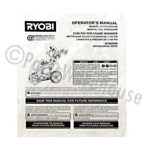
When specific elements show signs of degradation, prompt action is required. Look for visual indicators, such as cracks or excessive wear, that suggest a need for replacement. Consult the manufacturer’s specifications to identify compatible alternatives, ensuring seamless integration and functionality.