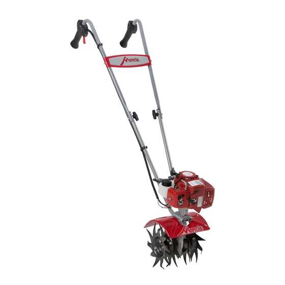
Understanding the structure and assembly of complex machinery is crucial for ensuring smooth operation and timely maintenance. Having a clear view of the various elements that contribute to functionality allows users to identify specific areas of interest, making upkeep and repairs more efficient. This overview will guide you through the essential elements that ensure optimal performance.
Each mechanical system is made up of carefully designed elements, each playing a unique role in overall efficiency. Whether for routine checks or more detailed servicing, knowing how these elements interact with each other is invaluable. In this guide, we will focus on the core components that make a difference in your equipment’s functionality.
Key connections and critical assemblies will be discussed in detail, providing a deeper understanding of how to maintain and service your machine. These insights will help you keep your equipment in peak condition and ready for reliable performance over the long term.
Overview of Mantis 7940 Components
This section provides a comprehensive look into the key elements that make up the functionality of the machine. Understanding the various mechanisms and their roles is essential for maintaining optimal performance and ensuring longevity.
Primary Structural Elements
- Engine Unit: The power source that drives the entire system, ensuring efficient operation.
- Handle Assembly: Allows for precise control and maneuverability during use.
- Fuel System: Responsible for supplying the necessary energy, it plays a critical role in the overall efficiency.
Operational Components
- Tilling Mechanism: A crucial feature designed for soil preparation, breaking up the ground with precision.
- Transmission System: Connects the power source to the tilling mechanism, ensuring smooth and consistent motion.
Engine Parts Breakdown
The internal components of a compact engine are carefully designed to work together in harmony. Each element plays a crucial role in ensuring smooth performance and long-term durability. A clear understanding of these components is essential for proper maintenance and troubleshooting.
The core of the system includes a cylinder, piston, and crankshaft. These elements convert energy into mechanical motion. The fuel system, including the carburetor, controls the air-fuel mixture, while the ignition system ensures proper combustion. Seals and gaskets prevent leaks, ensuring efficiency and protecting the internal mechanisms from damage.
Additional components such as the cooling system and exhaust play vital roles in temperature regulation and expelling gases. Understanding the functions of each element helps ensure optimal operation and performance over time.
Handle Assembly Structure
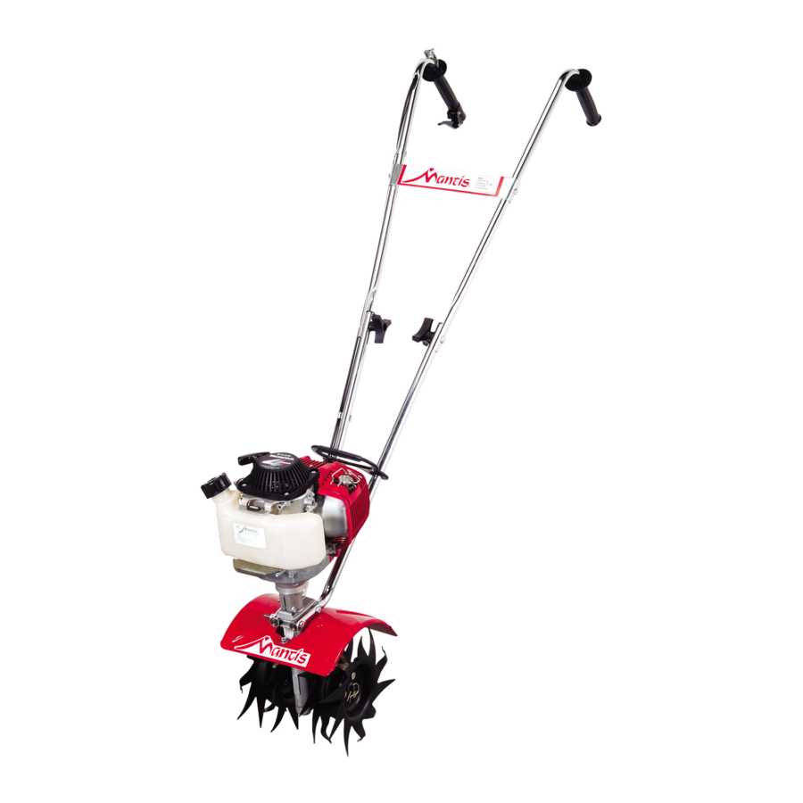
The handle assembly plays a crucial role in providing stability and control during operation. This section focuses on the construction and various components that contribute to the effective function of the handle system, ensuring ease of use and comfort for the operator.
Key Elements of the Handle System
The assembly consists of several key elements that are meticulously designed to offer both durability and ergonomic support. These elements include the grip, shafts, and various connection points, each contributing to the overall structure’s integrity and functionality.
Connection and Adjustment Features
An important feature of the handle system is its adjustable connections, which allow users to modify the height and angle to match their preferences. These adjustable components ensure that the equipment can be tailored to individual needs, enhancing comfort during extended use.
Transmission System Layout
The transmission system is essential for ensuring efficient power transfer between the engine and the mechanical components. It plays a crucial role in delivering the necessary torque to operate various functions, making the equipment perform optimally under varying conditions.
Power Distribution within the transmission is designed to maximize efficiency, adjusting speed and force to meet operational demands. The internal mechanism consists of multiple gears and shafts that work together, allowing seamless transitions between different stages of movement.
Key components of the system include the gearbox, which controls speed and direction, and the drive shaft, responsible for transferring power to the working elements. Proper alignment and maintenance of these parts ensure smooth operation and long-term durability.
Fuel Tank and Lines Configuration
The fuel system setup plays a critical role in ensuring smooth engine operation. Understanding the arrangement of the fuel container and its connecting tubes is essential for maintaining efficient performance and minimizing malfunctions. Proper alignment and secure attachment of the components help to prevent leaks and ensure consistent fuel flow to the engine.
Key elements in this configuration include the fuel storage unit, hoses, and clamps that secure the system. The flow of fuel from the tank to the engine must remain uninterrupted, which requires regular inspections and adjustments to maintain optimal efficiency.
Throttle Control Mechanism
The throttle control system plays a crucial role in managing the engine’s speed and performance. This mechanism allows the operator to adjust the power output, ensuring smooth operation and optimal functionality of the equipment. Understanding how this system works can help in maintaining efficiency and prolonging the life of the machine.
Component Function Throttle Lever Adjusts the engine speed by controlling airflow. Cable Connects the lever to the engine, transmitting movements. Spring Maintains tension and returns the lever to its default position. Throttle Plate Blades and Tines Design
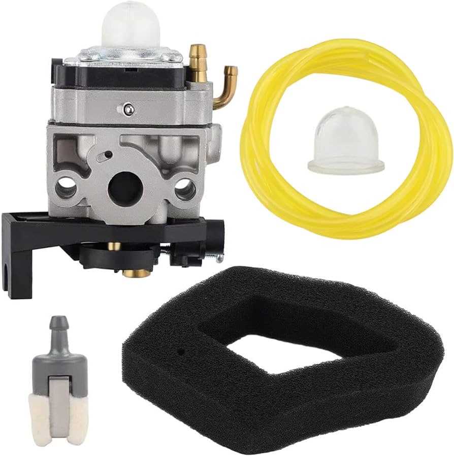
The structure of the blades and tines plays a crucial role in ensuring efficient soil preparation. Their configuration and sharpness directly influence the tool’s ability to break through different soil types, offering precision and control in gardening tasks.
The tines are typically designed with durability in mind, made from robust materials that withstand heavy use. The cutting edges are strategically shaped to maximize penetration while minimizing strain on the operator. This allows for smoother operation, even in compacted soil conditions, making gardening tasks more efficient.
Clutch System Composition
The clutch mechanism plays a vital role in the functionality of various machinery, facilitating the seamless transfer of power between components. Understanding its structure and components is essential for efficient operation and maintenance.
Key Components
- Clutch Plate: This element engages and disengages the power transfer, allowing for smooth operation.
- Pressure Plate: It applies force to the clutch plate, ensuring proper contact with the driving disc.
- Release Bearing: This component helps in disengaging the clutch during operation.
- Flywheel: Serves as a connection point and provides rotational stability during operation.
Functionality Overview
The clutch system operates by using friction to connect and disconnect components, which allows for controlled power transfer. Each part works together harmoniously to ensure the machinery functions smoothly, contributing to overall efficiency.
Air Filter Assembly Details
The air filtration component is essential for maintaining optimal performance and longevity of outdoor power equipment. This assembly ensures that the engine receives clean air, free from dust and debris, which is crucial for efficient combustion and operation. Understanding the structure and function of this assembly can enhance maintenance practices and improve overall equipment reliability.
Components of the Air Filtration System
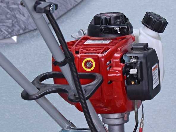
- Air Filter Element: The primary component that traps airborne particles.
- Filter Housing: The casing that encases the filter, providing structural support.
- Cover: Protects the filter element and ensures proper sealing.
- Mounting Brackets: Secure the assembly in place within the engine compartment.
Maintenance Tips
- Regularly inspect the air filter for dirt and damage.
- Replace the filter element as needed to ensure optimal airflow.
- Keep the filter housing clean to prevent clogging.
- Ensure that the cover is properly sealed to avoid unfiltered air intake.
Starter Mechanism Overview
The starter assembly is a crucial component in initiating the operation of a garden tool, facilitating the transition from rest to active use. This mechanism is designed to provide the necessary force to engage the engine, ensuring a reliable start-up process. Understanding the elements involved in this system can enhance maintenance practices and extend the lifespan of the equipment.
Components of the Starter Assembly
The starter mechanism typically includes several key elements, such as the pull cord, recoil spring, and starter pulley. The pull cord allows the user to manually engage the system, while the recoil spring ensures that the cord retracts smoothly after use. The starter pulley connects these components, facilitating the conversion of manual effort into rotational motion needed to crank the engine.
Maintenance and Troubleshooting
Regular inspection and maintenance of the starter assembly are essential for optimal performance. Common issues may include a worn pull cord or a malfunctioning recoil spring. Identifying these problems early can prevent more significant malfunctions, ensuring that the tool remains functional and reliable throughout its usage.
Frame and Housing Setup
The assembly of the structural components and outer casing is crucial for ensuring optimal performance and durability of the equipment. This section outlines the essential steps and considerations for correctly installing these vital elements, contributing to the overall functionality and efficiency of the machine.
Understanding Structural Components
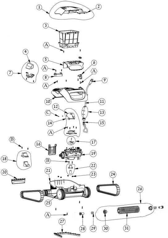
The structural framework serves as the backbone of the device, providing stability and support. It is important to verify that all sections are aligned correctly and secured firmly to prevent any wobbling or misalignment during operation. Pay close attention to the connection points, ensuring they are tightly fastened to enhance the integrity of the setup.
Installing the Outer Casing
The outer housing protects internal mechanisms from external elements and contributes to the aesthetic appeal. When attaching the casing, make sure to align it properly with the frame. Utilize the designated fasteners, ensuring each piece fits snugly to prevent vibrations that could lead to wear and tear over time. Regularly inspect the housing for any signs of damage or looseness to maintain the overall functionality of the apparatus.
Exhaust System Diagram
The exhaust assembly is a crucial component of any machinery that utilizes an internal combustion engine. This system facilitates the efficient expulsion of gases produced during the combustion process, ensuring optimal engine performance and reducing harmful emissions. Understanding the configuration of this system can aid in maintenance and troubleshooting, providing insights into the flow of gases and the connection of various components.
Key Components
Essential elements of the exhaust configuration include the muffler, catalytic converter, and exhaust pipes. Each component plays a significant role in directing exhaust gases away from the engine and minimizing noise. The muffler specifically helps in reducing sound levels, while the catalytic converter transforms harmful pollutants into less harmful emissions, contributing to environmental protection.
Functionality Overview
In operation, the exhaust system works by collecting gases from the engine and channeling them through the respective components. This process not only enhances performance by improving airflow but also helps in maintaining a safe operating environment. Regular inspection of the exhaust system is recommended to prevent leaks and ensure that all components are functioning effectively.
Ignition Parts and Wiring
The ignition system is a critical component in any small engine, responsible for generating the spark necessary for combustion. Understanding the various elements of this system, as well as their interconnections, is essential for effective maintenance and troubleshooting. This section provides an overview of the key components and wiring involved in the ignition setup.
Essential Components
The ignition assembly comprises several crucial elements, including the spark plug, ignition coil, and flywheel magnet. The spark plug is responsible for igniting the fuel-air mixture, while the ignition coil transforms the battery voltage into a high-voltage pulse. The flywheel magnet plays a pivotal role in producing the necessary magnetic field to energize the ignition coil.
Wiring Connections
Proper wiring is vital for the ignition system to function correctly. Each component must be connected according to the schematic to ensure reliable operation. Wires are typically routed from the ignition coil to the spark plug, with additional connections for grounding and safety features. Maintaining clean and secure connections will enhance performance and prolong the lifespan of the ignition components.