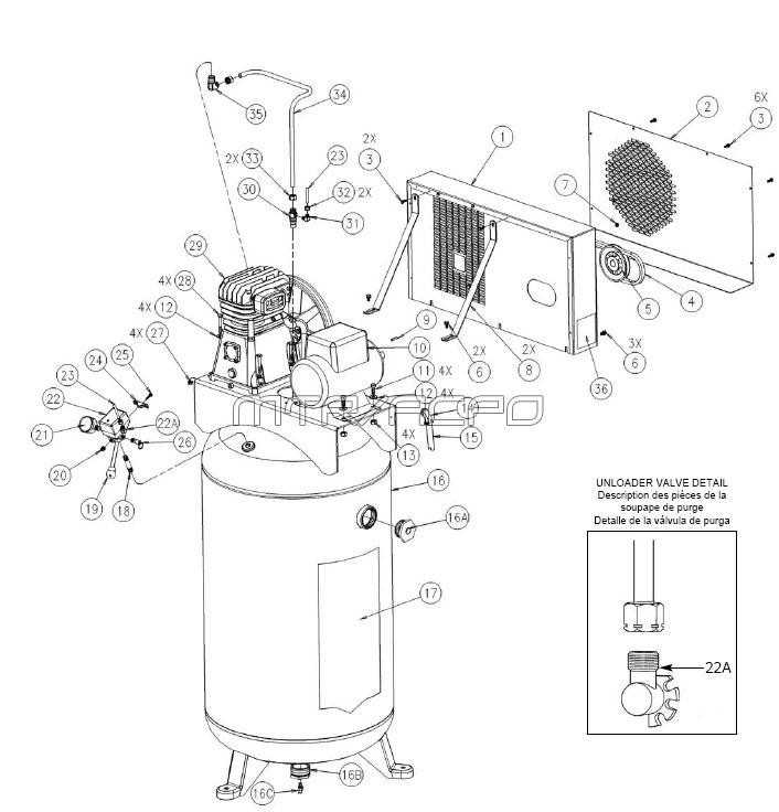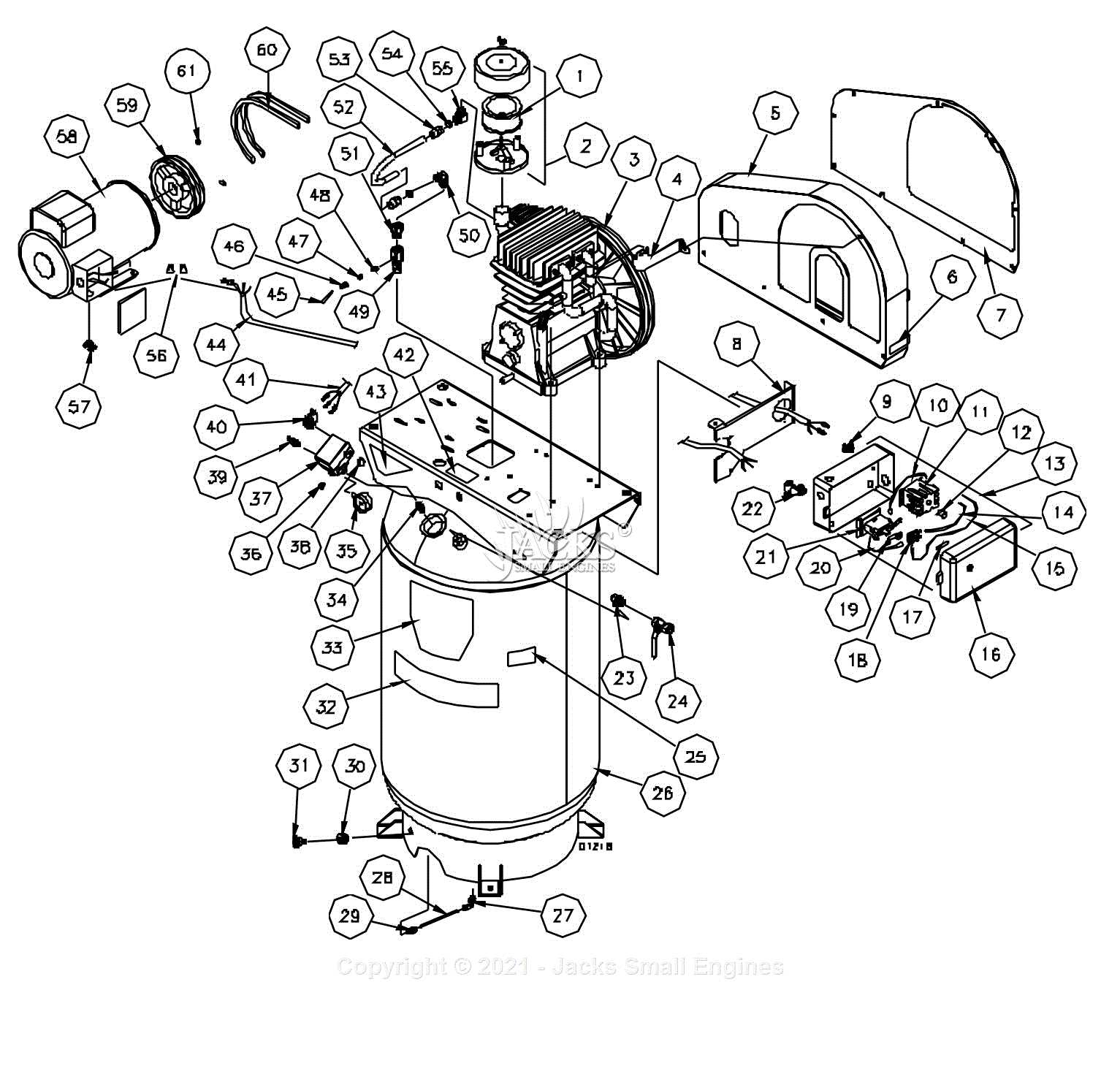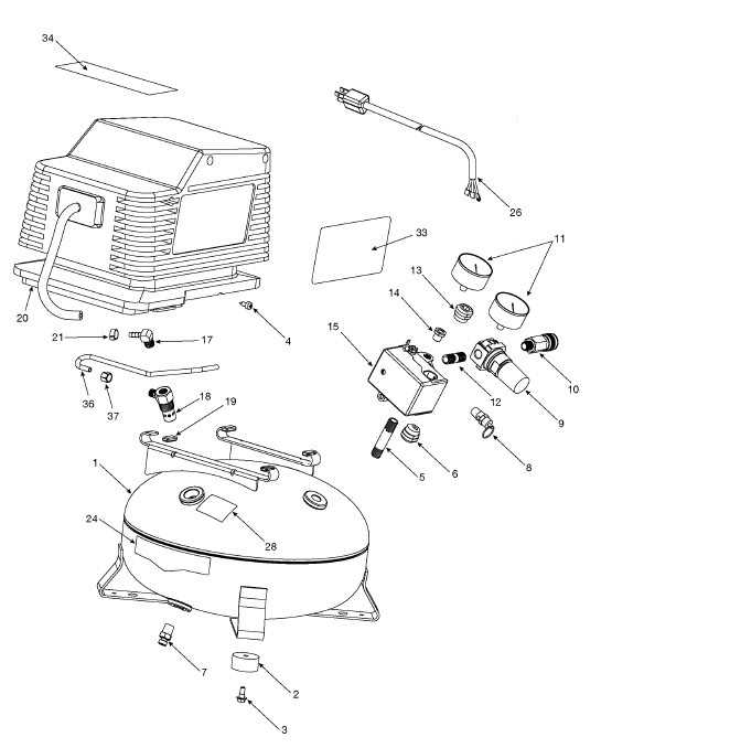
When working with mechanical equipment, it’s essential to understand how various components are arranged and how they interact with each other. By gaining a solid understanding of the internal layout, you can ensure smoother maintenance, quicker troubleshooting, and a more efficient overall operation.
Exploring the layout of a device gives insight into its functionality. The arrangement of different elements plays a crucial role in determining how efficiently a machine operates. Each element has its place, working in harmony with others to provide reliable performance.
Learning about the placement of key elements within machines not only helps in daily use but also in identifying potential issues. Knowing where to find specific elements can make repairs and regular maintenance much more straightforward and time-efficient.
Understanding the Components of an Air Compressor
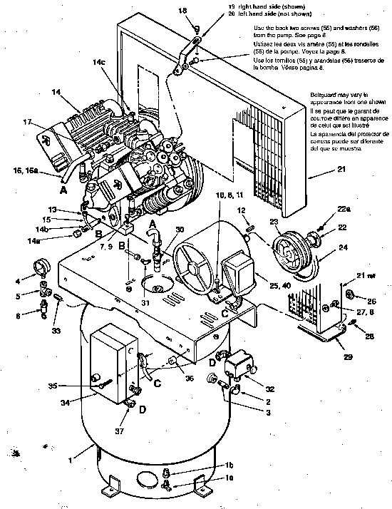
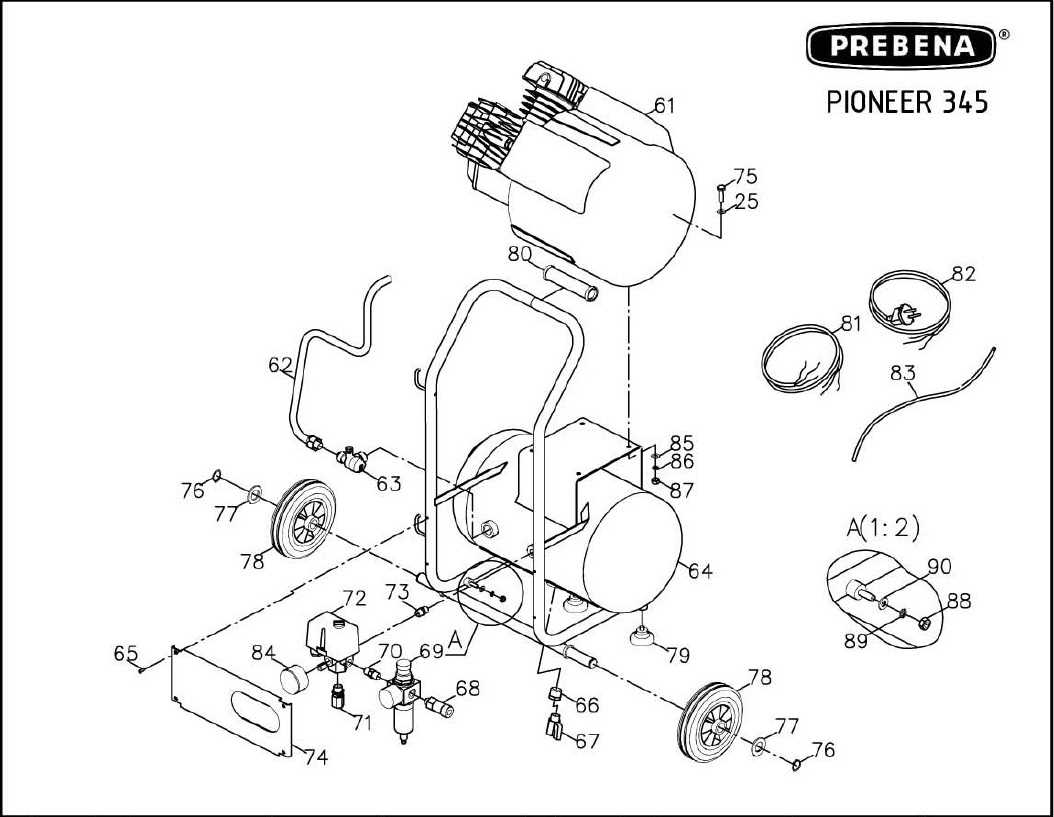
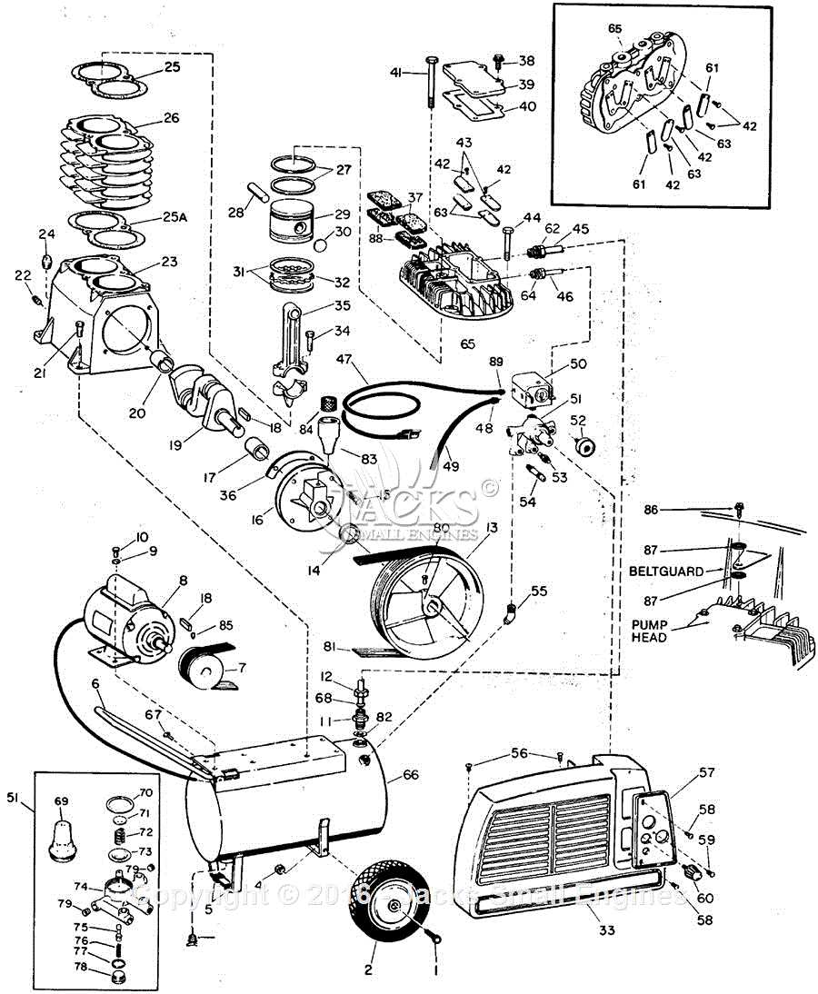
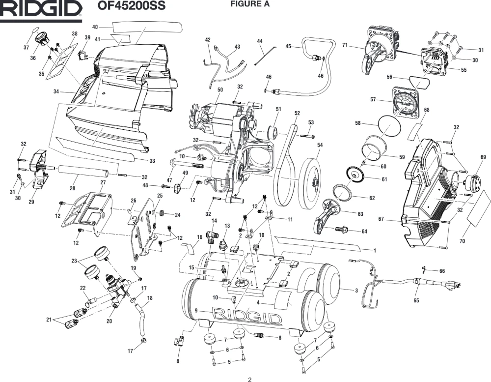
To fully grasp the mechanics of this device, it’s important to break down its various elements. Each part plays a specific role in ensuring the unit functions properly. From the primary mechanisms responsible for generating power to the smaller, more intricate pieces, every component is crucial to the overall operation.
The central unit is powered by a system that converts energy into motion, driving the other components. Valves control the flow of gases, regulating pressure, while storage units keep reserves ready for use when needed. Additional parts ensure cooling, lubrication, and safety measures are in place to prevent malfunctions.
Understanding how these elements work together provides insight into the unit’s reliability and efficiency, highlighting how critical each piece is in maintaining optimal performance.
Function of the Main Motor in Air Compressors
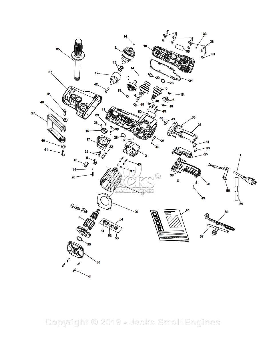
The main motor plays a crucial role in powering various types of pneumatic systems. Its primary responsibility is to convert electrical energy into mechanical force, driving the system’s core functions. Without the motor, the entire mechanism would be unable to generate the necessary force for operation, making it the central component of the overall setup.
How the Motor Drives the System
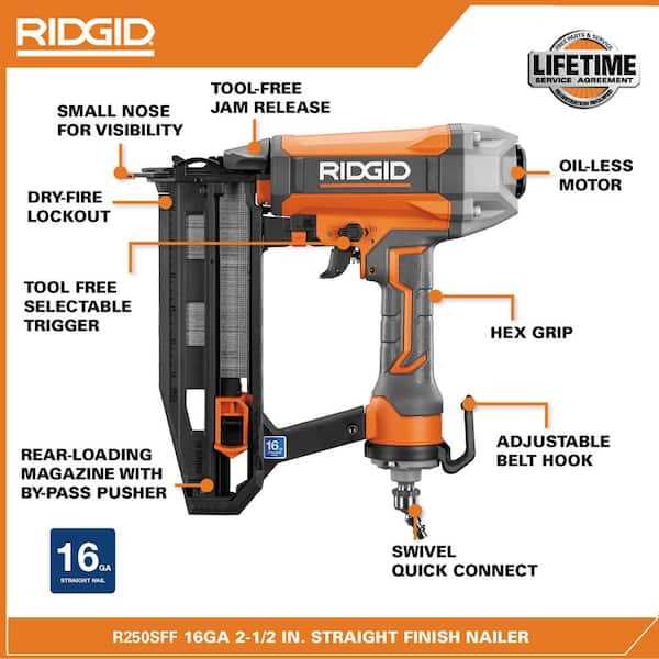
The motor is designed to provide consistent torque and rotational movement. This rotational energy is transferred to other components, which allows the system to perform its intended functions. The stability and performance of the entire setup largely depend on the motor’s efficiency and reliability.
Key Features of the Main Motor
- Provides consistent and stable power output
- Optimized for energy conversion and minimal energy loss
- Capable of sustaining prolonged periods of operation under heavy loads
These features ensure that the motor can meet the demands of the system without overheating or losing efficiency over time.
Role of the Pressure Switch in Operation
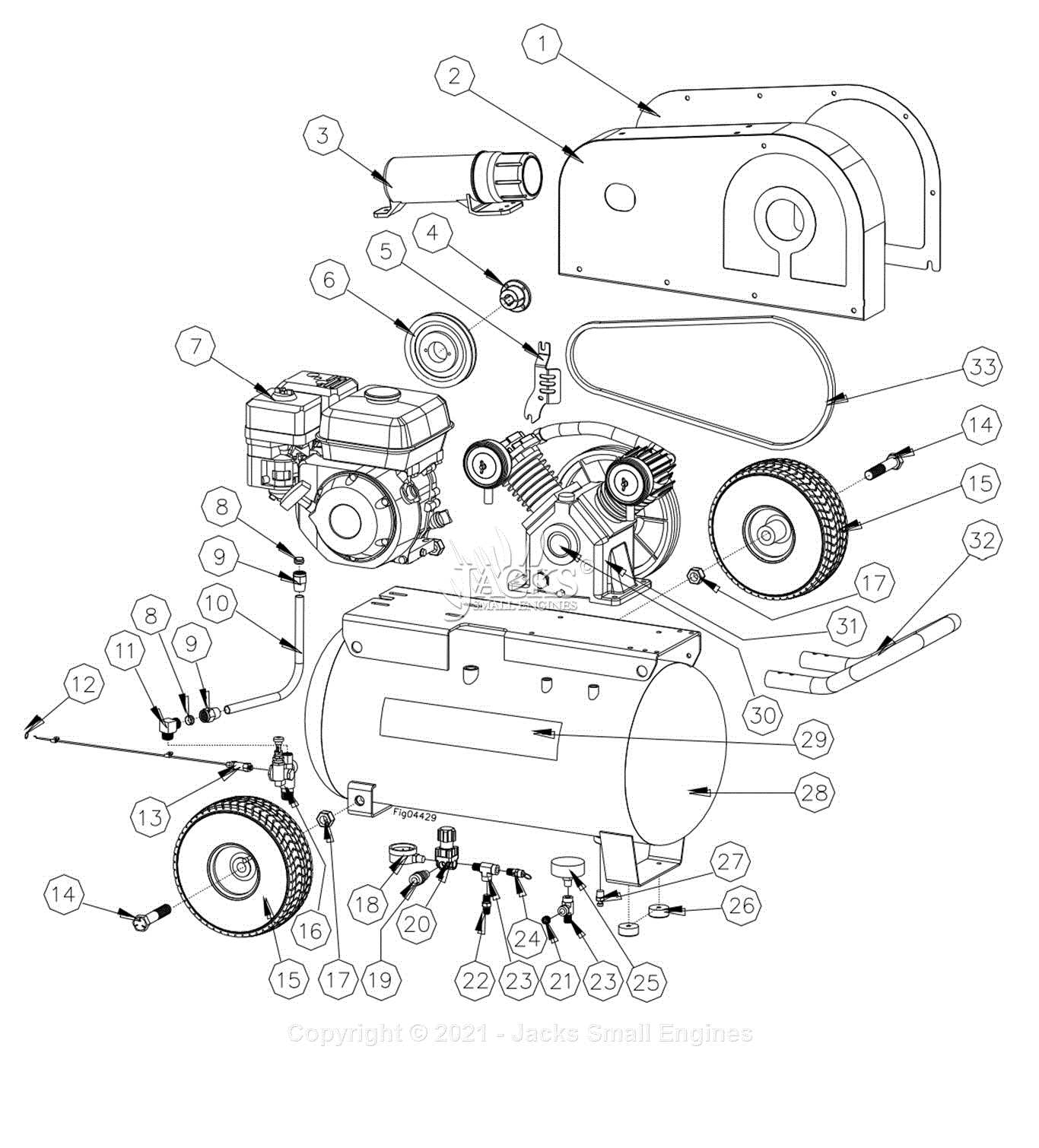
The pressure switch is a key component responsible for regulating system performance by managing pressure levels. It ensures efficient functionality by automatically turning the machine on or off based on preset thresholds, which prevents overloading and maintains safety during operation.
Main Functions of the Pressure Switch
- Monitors internal pressure and activates the system when levels drop below the desired point.
- Shuts down the system when the pressure reaches the maximum limit to avoid potential damage.
- Contributes to energy efficiency by minimizing unnecessary operation cycles.
Importance of Calibration
Proper calibration of the pressure switch is essential for smooth performance. If set incorrectly, the system may cycle too frequently or fail to maintain adequate pressure, impacting its reliability and lifespan. Routine checks ensure that the switch operates within its designated parameters.
Understanding the Air Tank and Its Importance
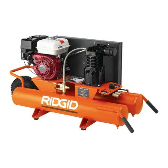
The tank plays a crucial role in the overall functionality of many systems that rely on stored energy for various tasks. This component ensures that sufficient pressure is available for smooth operation, contributing to both performance and safety. Without it, the entire process would be less efficient and more prone to interruptions.
One of the key benefits of this vessel is its ability to maintain a consistent supply of force, reducing the strain on the system during operation. By storing energy, it minimizes fluctuations and prevents overloading, thus prolonging the lifespan of other components.
| Feature | Benefit | ||||||||||||||||||||||||||||||||||
|---|---|---|---|---|---|---|---|---|---|---|---|---|---|---|---|---|---|---|---|---|---|---|---|---|---|---|---|---|---|---|---|---|---|---|---|
| Energy Storage | Provides a reserve for steady output and operation | ||||||||||||||||||||||||||||||||||
| Pressure Regulation | Maintains consistent force, preventing spikes or drops | ||||||||||||||||||||||||||||||||||
| Component | Function | ||||||||||||||||||||||||||||
|---|---|---|---|---|---|---|---|---|---|---|---|---|---|---|---|---|---|---|---|---|---|---|---|---|---|---|---|---|---|
| Valve | Controls the output by adjusting pressure. | ||||||||||||||||||||||||||||
| Gauge | Monitors the current level for accuracy. | ||||||||||||||||||||||||||||
| Adjustment Knob | Significance of the Safety Valve in Compressors
The safety valve serves a crucial role in maintaining the integrity and reliability of pressure systems. This essential component is designed to protect equipment from excessive pressure buildup, which can lead to catastrophic failures. Functionality: The primary function of the safety valve is to release pressure when it exceeds predetermined levels. By doing so, it prevents potential hazards such as explosions or mechanical damage, ensuring safe operation. Maintenance: Regular inspection and maintenance of the safety valve are vital for optimal performance. A well-functioning valve contributes to the longevity of the entire system, while a malfunctioning one can compromise safety and efficiency. The Purpose of the Drain ValveThe drain valve plays a crucial role in maintaining the efficiency and longevity of a system that utilizes pressurized resources. This component is designed to manage and release accumulated moisture and contaminants that can build up during operation. By allowing for the expulsion of excess liquid, the drain valve helps prevent corrosion and damage within the system. Regular maintenance of this feature is essential to ensure optimal functionality and to avoid potential operational issues. Furthermore, a properly functioning drain valve contributes to safety by minimizing the risk of pressure-related failures. It ensures that the internal environment remains clear of unwanted substances, thereby enhancing overall performance. In summary, this vital element not only supports the mechanical integrity of the apparatus but also promotes efficient operation by effectively managing moisture levels. Using a Pressure Gauge for Accurate Readings
Employing a pressure gauge is essential for obtaining precise measurements in various applications. This instrument allows users to monitor and adjust the levels effectively, ensuring optimal performance and safety during operation. Understanding how to utilize this device correctly can significantly enhance efficiency. To achieve accurate readings, it is vital to choose a suitable gauge that matches the requirements of the system being used. Different gauges have unique specifications, including range, accuracy, and sensitivity. Familiarity with these characteristics helps in selecting the right tool for the task at hand.
Proper placement of the gauge is also crucial. It should be installed in a location that minimizes interference and allows for unobstructed readings. Regular maintenance and calibration of the device are necessary to ensure continued accuracy over time. The Role of Air Filters in Maintaining EfficiencyEffective filtration is crucial for the optimal functioning of any pneumatic system. Clean filters help prevent contaminants from entering the machinery, ensuring smooth operation and prolonging the lifespan of components. By trapping dust, debris, and other impurities, these essential elements play a significant role in maintaining overall performance and reliability. Enhancing Performance
Regularly replacing or cleaning filtration units can significantly enhance the efficiency of the equipment. When filters are clogged, the system must work harder to draw in necessary elements, leading to increased energy consumption and potential overheating. By ensuring that filters are in good condition, users can achieve better output and reduced operational costs. Preventing Damage
Inadequate filtration can lead to severe damage to internal mechanisms. Contaminants can cause wear and tear on moving parts, resulting in costly repairs or replacements. Implementing a routine maintenance schedule that includes filter checks can mitigate these risks, safeguarding investments and maintaining the longevity of the system. Replacing the Compressor Belt for Optimal Performance
Maintaining efficient operation of your machinery often requires timely replacement of essential components. One critical element is the drive belt, which plays a vital role in ensuring smooth functionality. This section focuses on the importance of replacing the drive belt and how it can enhance overall performance. Signs That Replacement is Necessary
Recognizing when a belt needs to be replaced is crucial for avoiding potential issues. Common indicators include:
Steps to Replace the Drive BeltReplacing the drive belt is a straightforward process that can be done with basic tools. Follow these steps for effective replacement:
Identifying and Replacing Worn SealsSeals play a crucial role in maintaining the efficiency of any machinery. Over time, these components can wear down, leading to leaks and reduced performance. Recognizing the signs of deterioration early can save time and resources. This section will guide you through the process of identifying and replacing damaged seals to ensure optimal functioning. Signs of DeteriorationSeveral indicators can suggest that seals need replacement. Common symptoms include:
Replacement Process
Once worn seals are identified, replacing them involves a few straightforward steps. First, ensure the equipment is powered down and depressurized. Next, remove the affected components carefully to access the seal. After extracting the old seal, clean the area thoroughly to remove any debris or residue. Finally, install the new seal, ensuring a snug fit, and reassemble the parts before testing the system. |
