| Depth Adjuster |
Nail Gun Trigger Assembly Breakdown
The mechanism controlling the activation of a nail gun is built for both efficiency and safety. Understanding how the trigger system operates helps with troubleshooting and maintenance, ensuring the tool performs reliably under different conditions.
Components Overview
- Trigger lever – initiates the firing process when pressed.
- Safety mechanism – prevents accidental discharge without proper engagement.
- Spring – provides the necessary tension for reset after firing.
- Valve assembly – controls the airflow that drives the nails into the material.
Trigger Assembly Function
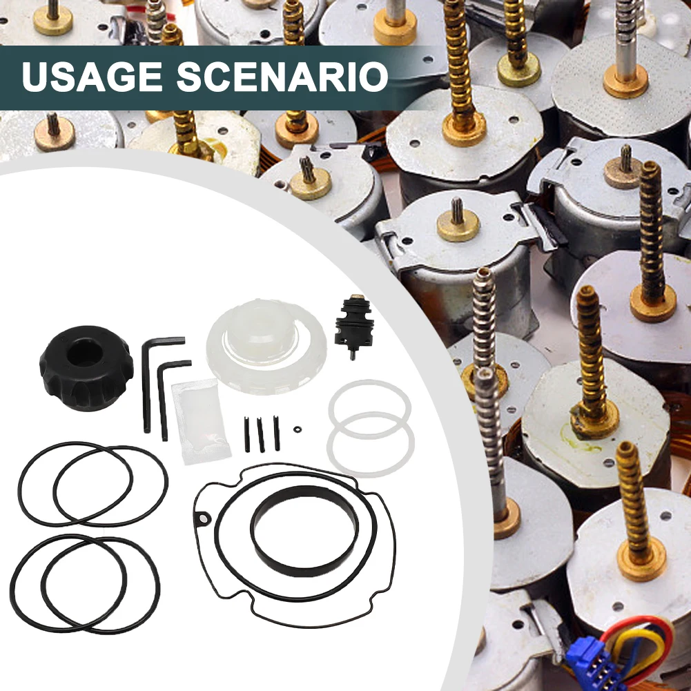
When the trigger is pulled, it releases the valve that directs compressed air to push the nail. The safety feature ensures the gun only fires when pressed against a surface, reducing the chance of accidental firing. The spring then returns the trigger to its original position, readying the tool for the next cycle.
- Engage safety – ensures proper positioning.
- Pull trigger – releases air for nail discharge.
- Trigger reset – spring returns mechanism to the start position.
Detailed View of the Cylinder Parts
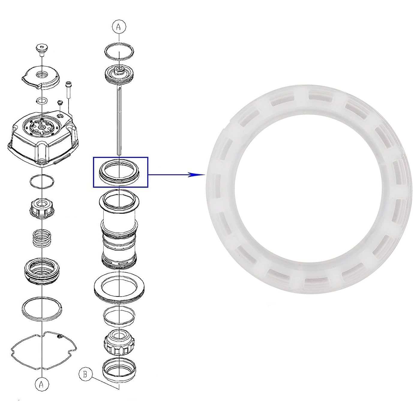
The cylinder is an essential component, contributing significantly to the overall performance. Its internal and external components must function in harmony to ensure smooth operation. Each element within the cylinder system plays a specific role in maintaining pressure and guiding movement efficiently.
Core Elements of the Cylinder
The primary structures include seals, rings, and the piston. Seals ensure airtight connections, preventing any loss of pressure. Rings contribute to minimizing friction between moving parts, while the piston is responsible for converting pressure into mechanical motion. These elements must be regularly inspected for wear to maintain efficiency.
Assembly Considerations
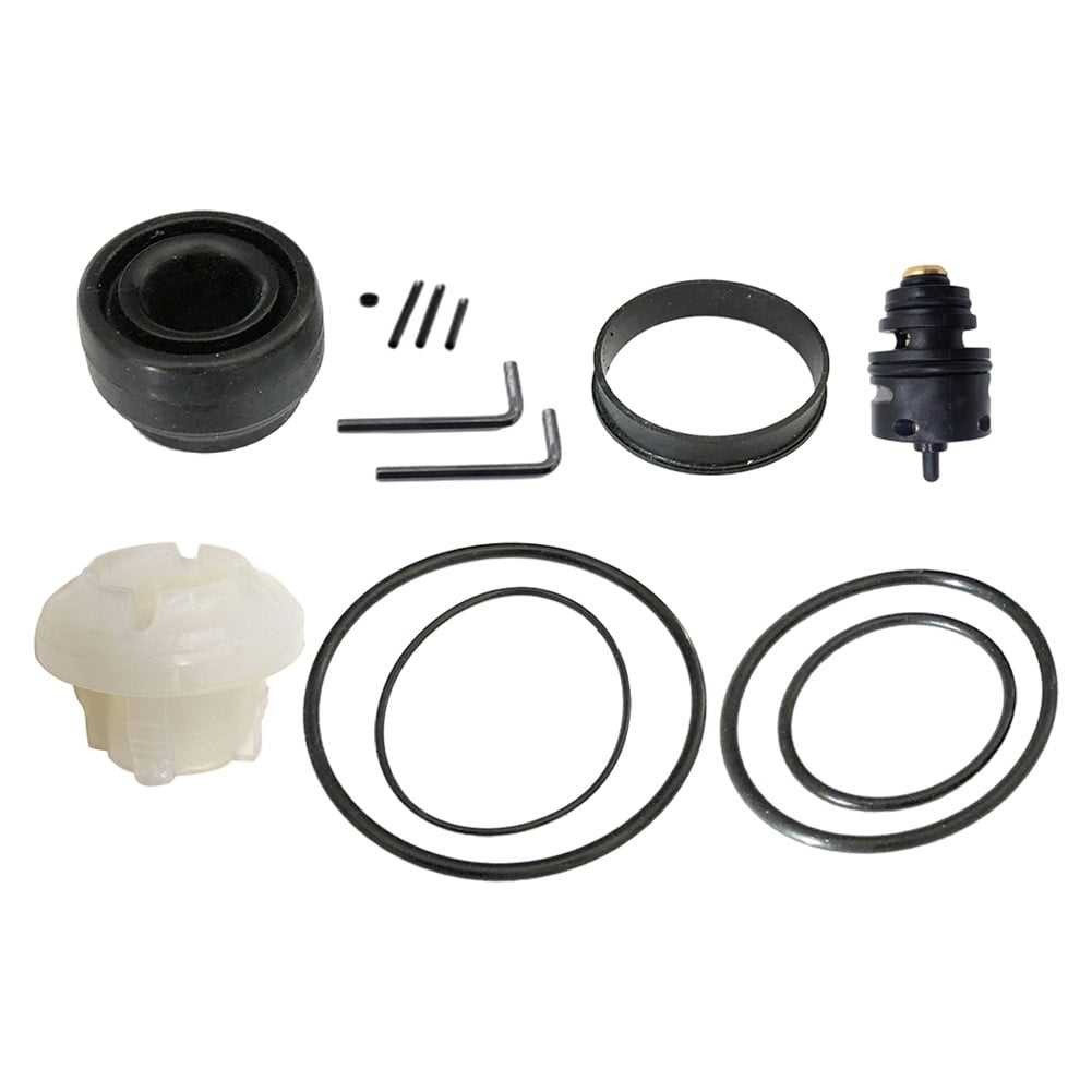
Correct alignment and placement of the cylinder’s components are vital for optimal functionality. Each part must fit precisely, ensuring minimal tolerance for movement outside intended parameters. Proper lubrication is also crucial to reduce wear and extend the lifespan of the entire system.
Piston and Driver Mechanism Layout
The piston and driver mechanism plays a crucial role in ensuring efficient force transfer during operation. This layout focuses on how the two elements work together to convert air pressure into a mechanical driving action, delivering consistent results with each cycle.
- The piston moves within the cylinder, powered by compressed air, creating the necessary force for operation.
- The driver blade, attached to the piston, transmits this force to the fastener, pushing it into the material with precision.
- Recoil is absorbed as the piston returns to its starting position, preparing the system for the next cycle.
- A spring or similar element assists in repositioning the piston quickly, ensuring minimal downtime between actions.
Each component in this mechanism is designed to withstand high pressure, ensuring long-term performance and reliability. Proper maintenance of these parts is essential for optimal function and efficiency.
Air Compressor Inlet Valve Structure
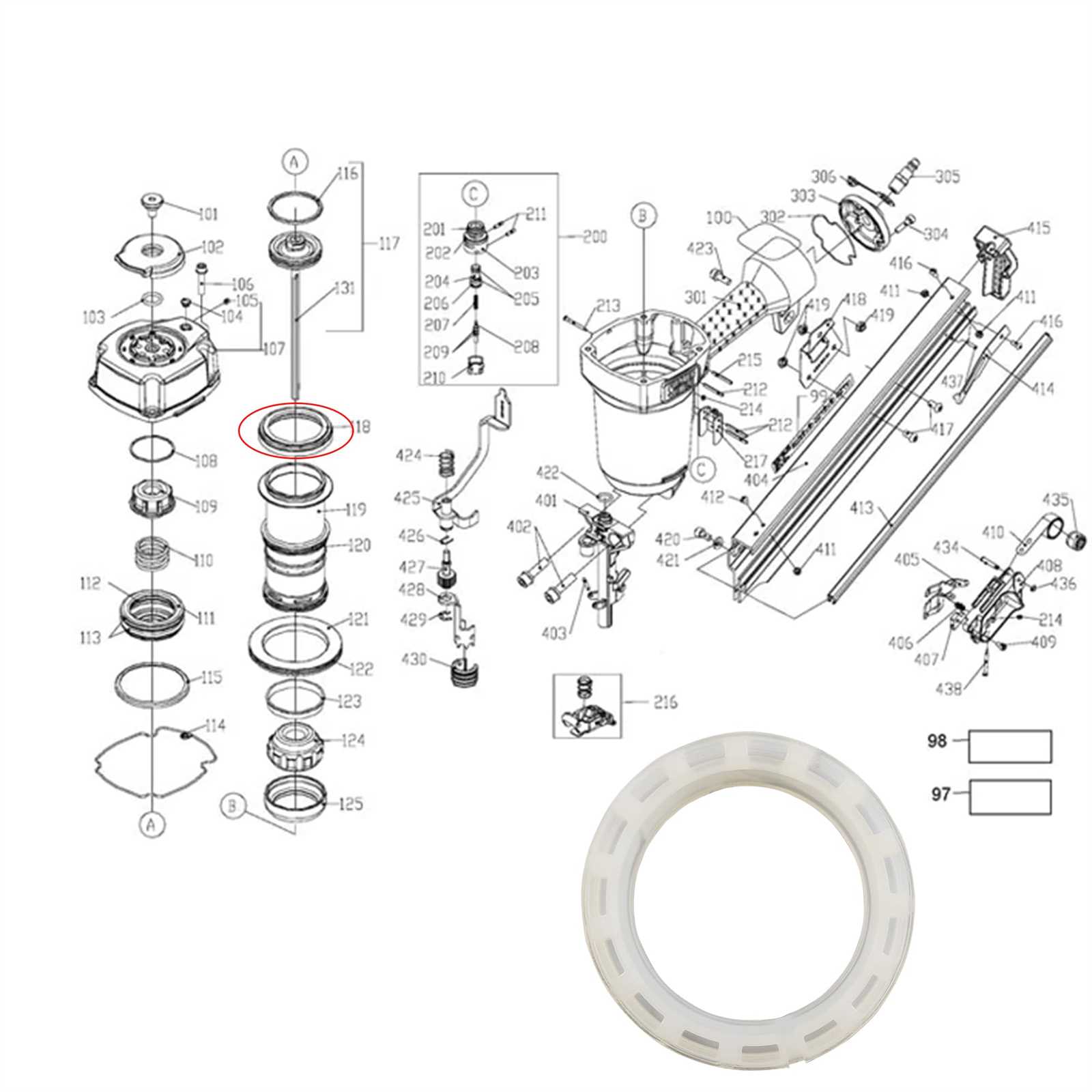
The inlet valve of an air compressor plays a crucial role in controlling the flow of air into the compression chamber. It opens to allow air to enter when the system requires it and closes to ensure efficient compression. Understanding its design is important for ensuring optimal operation of the compressor.
Main Components: The valve typically consists of a housing, a spring mechanism, and a sealing surface. These parts work together to regulate the movement of air during the intake cycle. The housing provides the structural support, while the spring ensures that the valve closes properly after air is drawn in.
Operation: When the compressor starts, the valve opens under pressure, allowing air to flow into the chamber. As the pressure builds, the spring pushes the valve shut, preventing any backflow and maintaining the pressure needed for efficient compression. This cycle repeats with every stroke of the compressor.
Handle and Grip Parts Identification
This section focuses on recognizing the various components related to the handle and grip of the tool. Understanding these elements is crucial for effective maintenance and proper functionality, ensuring optimal performance during use.
Key Components Overview
The primary components of the handle include the main grip, trigger, and safety features. Each element plays a vital role in ensuring the user’s control and safety while operating the equipment. Familiarity with these parts can aid in troubleshooting and repairs, enhancing the overall user experience.
Maintenance Tips
Regular inspection of the grip and handle components is essential for preventing wear and tear. Check for any signs of damage, such as cracks or looseness, which may compromise performance. Replacing worn components promptly can maintain the tool’s efficiency and ensure user safety.
Magazine and Feeder System Diagram
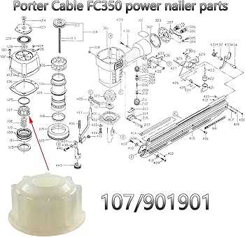
The magazine and feeder assembly is a crucial component of any fastening tool, designed to efficiently store and supply fasteners for continuous operation. This system enables seamless loading and unloading, ensuring that the tool can perform optimally without interruptions.
Within this assembly, various elements work together to guide and position fasteners accurately. The feeder mechanism typically includes a spring-loaded system that pushes the fasteners into place, while the magazine holds a reserve supply. Understanding the layout and function of these components can enhance maintenance and troubleshooting efforts, contributing to the overall reliability of the tool.
Exhaust Port Configuration and Design
The layout and structure of the exhaust outlet play a crucial role in the overall efficiency and performance of pneumatic tools. A well-designed exhaust system can enhance airflow, reduce noise levels, and prevent overheating, thereby ensuring optimal functionality during operation.
Importance of Exhaust Design
A thoughtfully engineered exhaust configuration can significantly impact the tool’s effectiveness. Proper venting allows for the rapid expulsion of gases, which minimizes back pressure and enhances the performance of the machine. This, in turn, leads to smoother operation and increased longevity of the tool.
Common Design Features
Several key characteristics define a successful exhaust port design. These may include the diameter of the outlet, the angle of discharge, and the presence of baffles to manage sound levels. Each feature must be carefully considered to achieve the desired balance between performance and noise reduction.
Internal Seals and Gaskets Placement
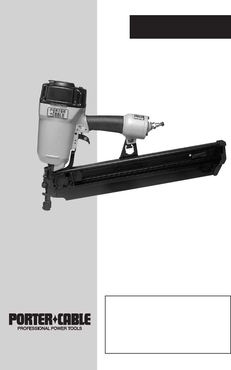
The proper arrangement of internal seals and gaskets is crucial for maintaining optimal performance and preventing leaks in power tools. These components serve as barriers, ensuring that air and fluids do not escape from their designated areas. Understanding their placement helps in achieving a reliable operation and extending the tool’s lifespan.
When installing these elements, it is essential to follow the manufacturer’s specifications. Each gasket and seal should fit snugly in its designated groove or channel, allowing for a secure and effective seal. Regular inspection and maintenance of these components will help identify wear and tear, ensuring that the tool operates efficiently.
Guide for Safety Mechanism Components
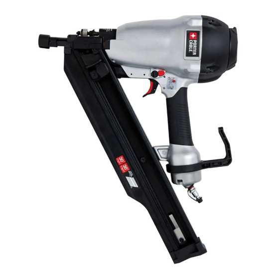
This section provides an overview of the essential components that ensure the safe operation of power tools. Understanding these elements is crucial for maintaining optimal performance and preventing accidents during use. Proper knowledge and regular inspection of these components contribute to a safer working environment.
| Component Name |
Function |
| Trigger Lock |
Prevents accidental activation of the tool. |
| Safety Guard |
Protects the user from debris and moving parts. |
| Brake System |
Stops the tool quickly to prevent injury. |
| Power Switch |
Controls the flow of electricity to the motor. |
| Overload Protector |
Shuts off power to prevent overheating. |
Spring and Pin Assembly Illustration
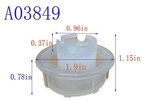
This section provides a visual representation of the compression mechanism that plays a crucial role in the operation of the device. Understanding the arrangement of the spring and pin components is essential for effective maintenance and repair.
Spring Functionality: The spring serves as a vital element that stores energy and facilitates the return action of the mechanism. It ensures that the moving parts operate smoothly and efficiently, enhancing overall performance.
Pin Configuration: The pin acts as a pivot point, allowing for controlled movement within the assembly. Its proper placement is critical for maintaining alignment and ensuring that the device functions as intended.
Overall, a clear illustration of these components aids technicians in grasping their significance and aids in troubleshooting potential issues.
O-Ring Replacement Parts Description
O-rings play a crucial role in ensuring a secure and leak-free connection within various tools and equipment. These small yet vital components are designed to create a tight seal between different parts, preventing the escape of fluids or gases. Understanding their importance can help in maintaining optimal performance and extending the lifespan of the device.
Types of O-Rings
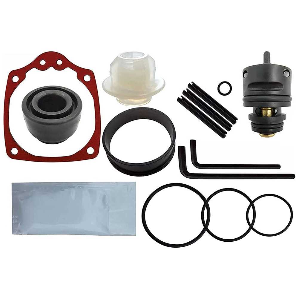
Different types of O-rings are available, each suited for specific applications. Common materials include rubber, silicone, and nitrile, which offer varying degrees of resistance to temperature and chemicals. Selecting the right type is essential for achieving the desired sealing effect.
Installation Tips
When replacing O-rings, it is important to ensure that the new component fits snugly into the designated groove. Clean the surfaces thoroughly before installation to remove any debris or old lubricant, which could compromise the seal. Proper alignment is also key to achieving an effective seal.
