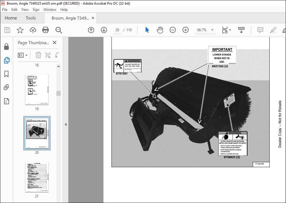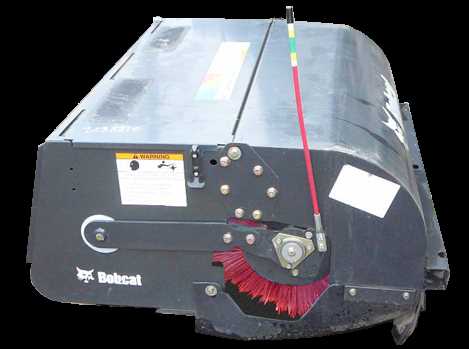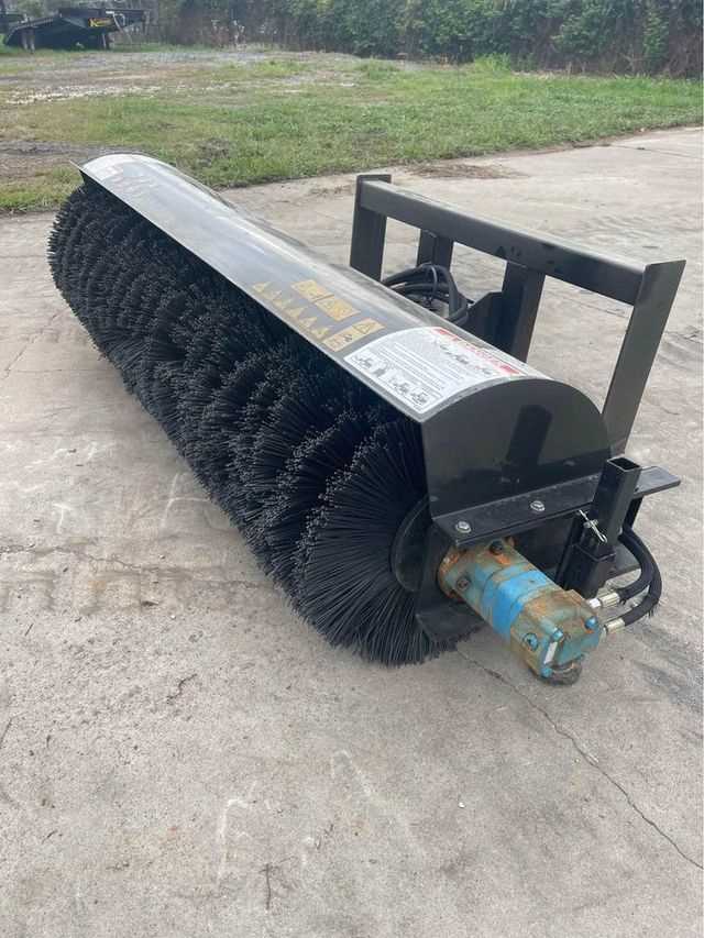
In the world of heavy machinery, attachments designed for sweeping and clearing debris are indispensable tools. These specialized accessories are engineered to tackle various surfaces, whether in construction zones, streets, or outdoor facilities. Their design ensures that they can efficiently handle a range of materials while providing consistent and thorough cleaning performance.
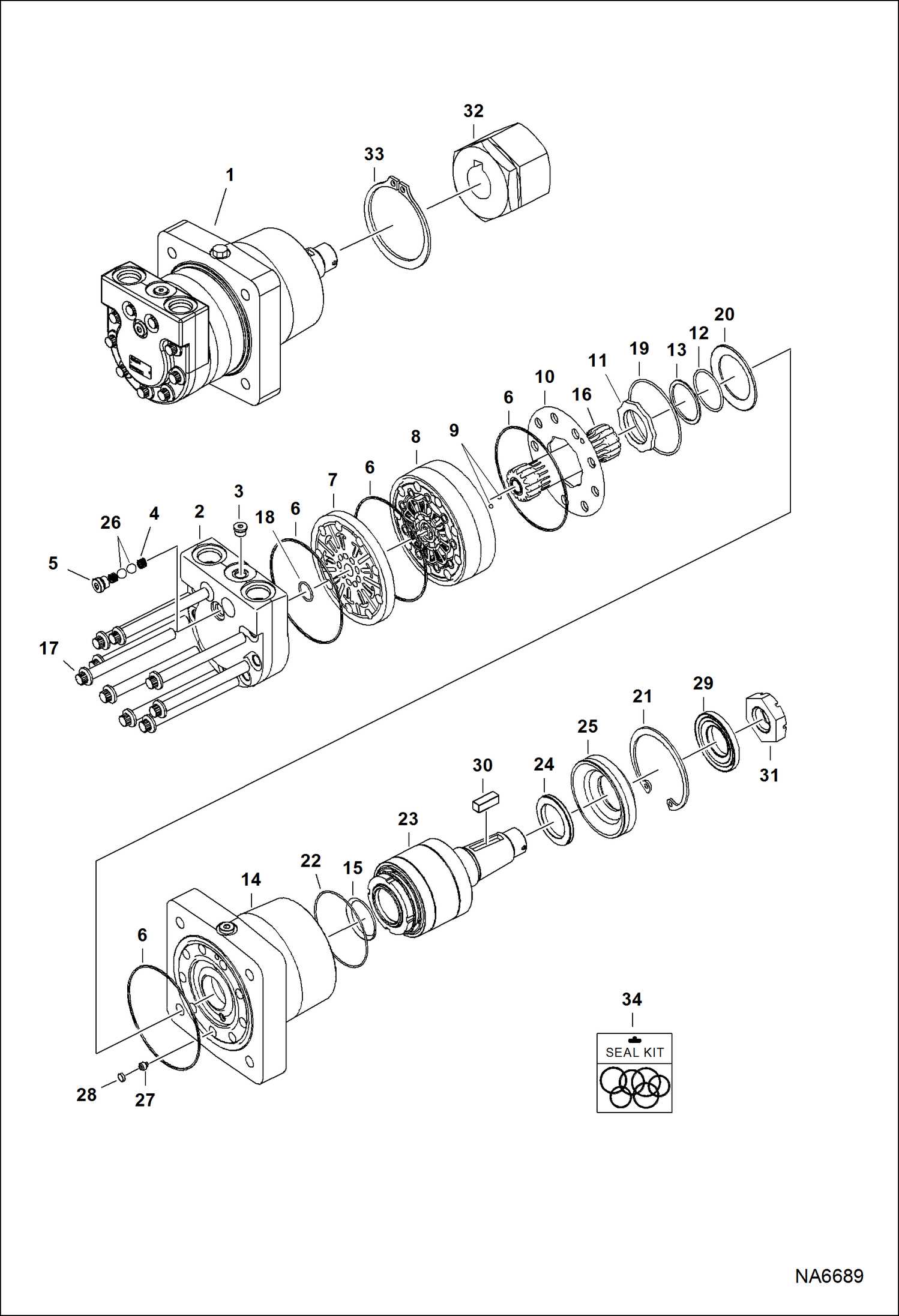
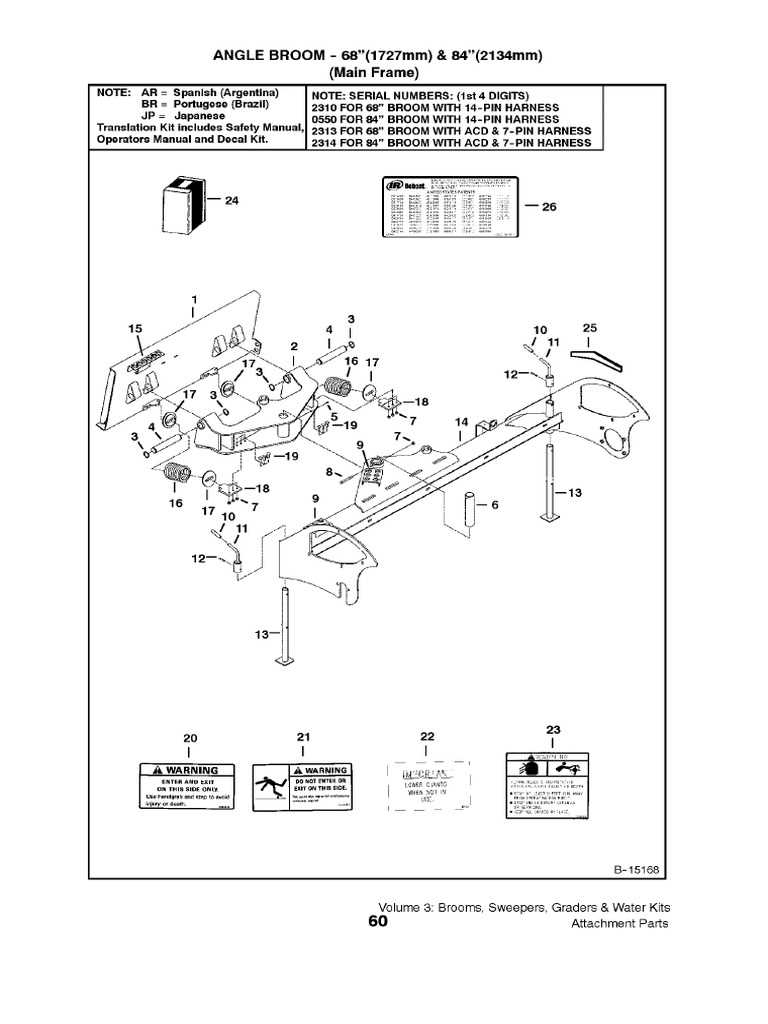
Delving into the mechanics of this particular tool reveals a complex network of interconnected elements. Each piece plays a crucial role in ensuring smooth operation, from the driving mechanism to the bristle assembly. Knowing how each part functions and interacts with the others is key to maintaining optimal performance and extending the lifespan of the equipment.
This guide offers a clear an
Bobcat 68 Angle Broom Overview
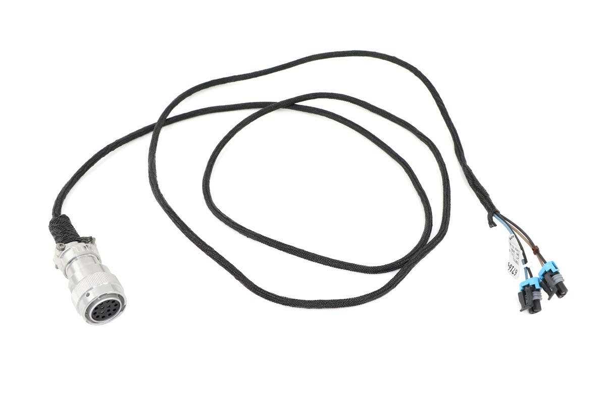
Designed for efficient surface cleaning, this tool is perfect for clearing debris from streets, driveways, and construction sites. Its unique design allows for optimal sweeping performance, handling a variety of materials with ease, from dirt and leaves to light snow. Adaptable to different terrains, it provides a versatile solution for keeping outdoor areas clear and tidy.
- Versatile operation on multiple surfaces
- Durable construction for extended use
- Effective at handling diverse types of debris
- Optimized for easy attachment and detachment
With its sturdy frame and ability to ta
Essential Components of the Angle Broom
The cleaning attachment is a versatile tool designed for efficient surface maintenance. It consists of a variety of interconnected elements, each playing a vital role in its operation. Understanding the key components ensures proper functionality and helps in identifying potential maintenance needs.
| Component | Description | ||||||||||||||||||||
|---|---|---|---|---|---|---|---|---|---|---|---|---|---|---|---|---|---|---|---|---|---|
| Brush Assembly | A rotating mechanism equipped with bristles that effectively sweeps away debris and dirt from different surfaces. | ||||||||||||||||||||
| Motor Housing | This section contains the drive unit that powers the sweeping motion, ensuring smooth and consistent operation. |
| Component | Function
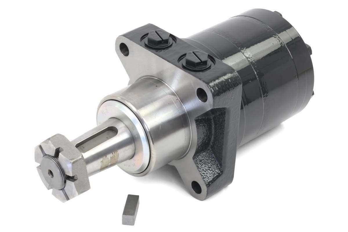
Hydraulic Motor: Key DetailsThe hydraulic motor is an essential component in various machinery, providing the necessary force for efficient operation. It converts hydraulic energy into mechanical motion, enabling the equipment to perform a range of tasks with precision and power. Understanding its key aspects can enhance maintenance and improve performance. When evaluating the hydraulic motor, several factors come into play, such as its construction, efficiency, and compatibility with other elements of the system. Below is a table outlining important specifications and features to consider:
By focusing on these crucial details, operators can ensure that the hydraulic motor operates smoothly, maximizing the efficiency of the entire system. Importance of the Sweeper ControlsThe efficiency of any cleaning mechanism significantly relies on the user interface and operational levers. These components are essential for ensuring precise maneuverability and optimal functionality. Understanding their significance can enhance the performance and longevity of the equipment, contributing to a more productive experience. Enhanced ManeuverabilityThe controls allow for seamless navigation and adjustments during operation. Properly designed interfaces facilitate the following:
Operational SafetySafety is paramount in any equipment operation. A well-structured control system contributes to:
How to Replace the Broom Bearings
Maintaining the rotating mechanism of your equipment is essential for optimal performance and longevity. One common task involves replacing the supporting elements that allow for smooth operation. This guide will walk you through the necessary steps to complete this procedure efficiently. Before starting, ensure you have the right tools and components. The following list includes the items you’ll need:
Follow these steps to replace the supporting elements:
By following these steps, you can efficiently replace the supporting elements of your equipment, ensuring continued reliability and effectiveness in your tasks. Safety Features of Bobcat Angle Brooms
When it comes to operating heavy machinery, ensuring user safety is paramount. Modern equipment is equipped with various protective elements that enhance operational security, allowing operators to work efficiently while minimizing risks. Understanding these features is crucial for anyone involved in maintenance or operation. Protective Mechanisms
Safety systems are designed to prevent accidents and injuries during use. Key mechanisms include automatic shut-off functions, which engage when detecting hazardous situations. Additionally, visual indicators provide operators with real-time information about the machine’s status, ensuring they remain aware of any potential issues. User-Friendly ControlsErgonomically designed controls contribute significantly to safety by allowing for intuitive operation. Operators can easily access and manipulate the controls without stretching or twisting, reducing the risk of strain or loss of control. This design philosophy enhances overall efficiency while maintaining a focus on user protection.
Troubleshooting Common Parts Issues
When working with specialized equipment, encountering difficulties with components is not uncommon. Identifying and resolving these issues can significantly enhance performance and prolong the lifespan of the machinery. This section focuses on common challenges faced by operators and provides practical solutions to ensure efficient operation. One frequent concern involves wear and tear on specific elements, which can lead to decreased efficiency. Regular inspection and timely replacement of worn components are essential. Additionally, keeping an eye on connections and fittings can prevent minor issues from escalating into major malfunctions. Another typical problem is misalignment, which may cause excessive strain on certain parts. Ensuring that all components are correctly aligned during installation is crucial for optimal function. If misalignment occurs, adjustments should be made promptly to avoid further damage. Finally, understanding the signs of potential issues, such as unusual noises or vibrations, can help in early detection. Operators should remain vigilant and perform routine maintenance checks to address any abnormalities before they impact the overall performance of the equipment. |
|---|
