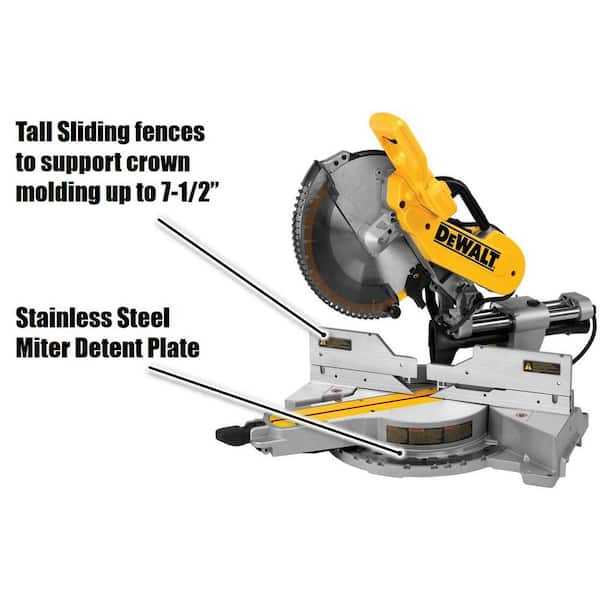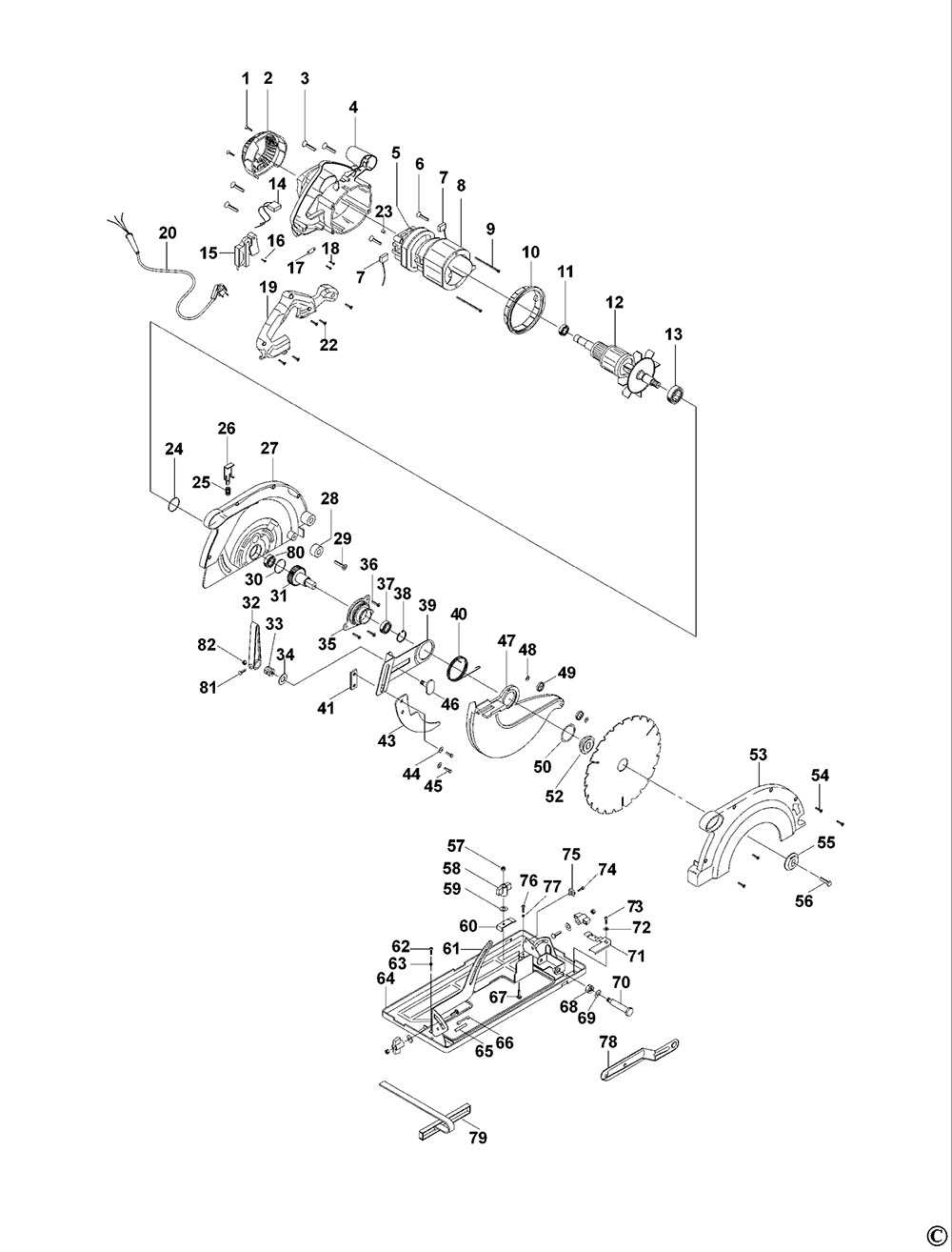
Understanding the structure and layout of essential components in high-performance cutting equipment is crucial for both maintenance and effective operation. Each element plays a vital role in ensuring the tool works seamlessly, offering precision and durability during use. By familiarizing yourself with these elements, you can enhance the efficiency and longevity of your equipment.
In this section, we’ll explore how different mechanical parts come together to form a reliable and efficient cutting machine. From the arrangement of moving pieces to the stationary fixtures, every detail is meticulously designed to optimize performance. With a clear understanding of these connections, identifying and resolving potential issues becomes more intuitive.
Whether you’re a seasoned technician or a DIY enthusiast, having
Understanding the Dewalt Miter Saw Structure
The structure of a power cutting tool is designed to ensure precision and durability. Comprising several interconnected components, it allows users to make accurate cuts across various materials. A robust frame and adjustable elements form the core of this system, ensuring smooth operation and long-lasting performance in both professional and home environments.
Key Components of the Power Tool
At the heart of the tool lies its cutting mechanism, supported by a stable base and a flexible arm. These components work together to provide steady and consistent cuts.
Key Components of a Miter Saw
Every cutting tool consists of various essential elements that work together to ensure smooth and precise operation. These components are critical in determining the functionality and accuracy of the device, providing stability, control, and efficiency during usage. Understanding each part helps users maintain the equipment and achieve optimal performance.
Base Platform: This sturdy foundation supports the entire tool and holds the material securely during operation. It ensures balance and helps to keep the cutting process steady and accurate.
Cutting Blade: The sharp disc is responsible for making cuts through the material. Different types of blades are available, designed to handle a
Exploring the Blade Assembly of Dewalt Saws
The blade system is a crucial element of any cutting tool, designed to ensure precision and durability during operation. Understanding the individual components of this mechanism helps improve efficiency and prolong the tool’s lifespan. Below, we break down the key parts involved in the functioning of the blade unit.
- Blade Guard: The protective cover that keeps the user safe from accidental contact during use.
- Mounting Plate: A crucial element that holds the cutting edge securely in place while maintaining proper alignment.
- Adjustment Kn
Handle and Trigger Mechanism Overview
The handle and trigger system is a crucial part of any cutting tool, responsible for initiating and controlling its operation. Understanding how this mechanism functions is essential for ensuring smooth and safe usage. The design incorporates various components that work together to provide stability, ease of control, and proper activation of the tool.
Main Components of the Handle Assembly
The handle unit typically consists of ergonomic grips to offer comfort during extended use. Inside the handle, the trigger mechanism is connected to the internal control circuitry, allowing the user to start and stop the tool with minimal effort. Some models may feature additional safety buttons or locks that prevent accidental activation.
Trigger Operation and Maintenance
The Importance of the Base and Fence
The foundation of any cutting tool, particularly those designed for precision, relies on the stability and alignment provided by its base and fence. These components ensure that the materials being worked on remain secure and in place, allowing for accurate and safe operations. Without a reliable support system, even the best blade will struggle to deliver precise results.
Several factors make these parts crucial in achieving optimal performance:
- Stability: A well-built base offers a solid foundation that minimizes vibrations, ensuring smoother and more controlled movements during use.
- Alignment: The fence plays a critical role in keeping materials straight, preventing unwanted shifts and ensuring cuts are made at the correct angle.
- How the Bevel Adjustment System Works
The bevel adjustment mechanism allows for precise angular cuts, enabling the user to tilt the cutting tool to a specific angle. This system is designed to offer flexibility and accuracy, especially when working with angled edges. It typically consists of various components that work together to ensure smooth operation and exact positioning.
- Locking Mechanism: The primary function of the locking component is to secure the angle once adjusted, preventing unintended movement during use.
- Angle Scale: A clearly marked scale helps to set the desired angle accurately, allowing the operator to match specific measurements for consistent results.
Explaining the Saw’s Motor Housing
The motor housing is a critical component that encapsulates the main driving mechanism of the tool. This structure is designed to protect the internal motor from external elements while ensuring optimal performance during operation. Its design contributes to the overall durability and functionality of the equipment, allowing it to withstand rigorous use.
Typically constructed from robust materials, the housing provides stability and minimizes vibrations. This enhances precision and control while cutting various materials. Additionally, the housing often includes ventilation openings that help dissipate heat generated during operation, ensuring the motor remains cool and functions efficiently.
Feature Description Material Durable compounds designed to withstand wear and tear. Ventilation Openings to allow air circulation and cooling of the motor. Vibration Dampening Design elements that reduce vibrations for improved cutting accuracy. Accessibility Features that facilitate easy maintenance and inspection of the motor. Guide to the Dust Collection System
The efficiency of any cutting tool can be significantly enhanced with an effective debris management mechanism. This system plays a crucial role in maintaining a clean workspace and ensuring optimal performance during operation. By minimizing airborne particles and collecting waste material, users can improve visibility and reduce cleanup time.
Implementing a well-designed collection system not only promotes a safer working environment but also extends the lifespan of the tool by preventing dust accumulation in vital components. Understanding the features and functionalities of the collection system is essential for maximizing its effectiveness. This guide will explore the various aspects of a typical collection mechanism, highlighting the best practices for setup and maintenance.
Regular maintenance of the collection system is crucial for optimal performance. Cleaning the filters and checking for blockages should be part of routine upkeep to ensure that the system operates smoothly. Additionally, using compatible accessories can enhance the overall efficiency of the debris management process. Proper adjustments and configurations tailored to specific tasks will yield the best results, allowing users to focus on precision without distraction.
Adjusting the Saw Arm and Pivot
Proper calibration of the arm and pivot mechanism is essential for achieving precise cuts. This process ensures that the tool operates smoothly and maintains accuracy throughout its use. By making the necessary adjustments, users can enhance the functionality and extend the lifespan of their equipment.
Understanding the Mechanism
The arm and pivot system are critical components that allow for versatile cutting angles. Familiarizing oneself with how these parts interact can simplify the adjustment process. Inspecting the connections and identifying any wear can help in pinpointing necessary modifications.
Steps for Adjustment
To adjust the arm, start by loosening the lock screws that secure the pivot. Gently move the arm to the desired angle, ensuring that it aligns with the measurement guides. Once positioned correctly, retighten the screws to lock the arm in place. Regular checks and calibrations will prevent misalignment and enhance cutting precision.
Replacing the Miter Scale and Indicator

Ensuring accurate angle measurements is crucial for precise cuts in any woodworking project. The miter scale and indicator play a significant role in this process, providing essential reference points. Over time, these components may wear out or become misaligned, necessitating replacement to maintain optimal performance.
Steps for Replacement
- Gather Necessary Tools: Ensure you have the appropriate tools for the job, such as a screwdriver and replacement components.
- Power Off the Tool: Always disconnect the tool from the power source before beginning any maintenance or replacement work.
- Remove the Old Scale: Carefully detach the existing scale from its mounting position. Pay attention to any screws or fasteners that may need to be removed.
- Install the New Scale: Align the new scale in the correct position and secure it using the appropriate fasteners.
- Replace the Indicator: If the indicator is also worn or damaged, remove it and install the new one in the designated spot.
- Test for Accuracy: Once the new components are installed, reconnect the power and perform a test cut to ensure that the measurements are accurate.
Maintenance Tips
- Regularly check the alignment of the scale and indicator to prevent inaccuracies.
- Clean the components periodically to remove any debris that may affect their function.
- Store the tool in a dry place to minimize wear on the scale and indicator.
Troubleshooting Common Part Failures
When using precision cutting tools, users may encounter issues stemming from various components. Identifying and resolving these failures is crucial to maintaining efficiency and ensuring safety during operation. This section will cover common problems associated with individual components, their potential causes, and solutions to restore functionality.
Component Common Issues Possible Causes Recommended Solutions Motor Tool not starting Faulty power supply, damaged motor Check connections, replace motor if necessary Blade Inconsistent cuts Dull or damaged blade Sharpen or replace the blade Guard Guard not functioning Obstruction or damage Clear obstruction, repair or replace guard Switch Intermittent operation Worn switch contacts Inspect and replace the switch if needed