Belt T
Spindle Types and Compatibility
Understanding the different variations of spindles and their compatibility is crucial for ensuring optimal performance and longevity of machining equipment. Each type of spindle is designed with specific functions and features that cater to various operational needs. Choosing the appropriate spindle type enhances efficiency and precision during operations.
There are several common types of spindles, each offering distinct advantages:
- Live Spindles: These are powered directly and provide consistent rotation during operation, ideal for drilling and milling tasks.
- Dead Spindles: These spindles do not rotate independently but are crucial for supporting workpieces during machining.
- Variable Speed Spindles: Featuring adjustable speed settings, these spindles allow for versatility in processing different materials.
- High-Speed Spindles: Designed for precision work, high-speed spindles enable faster cutting and improved finish quality.
When selecting a spindle, consider the following compatibility factors:
- Size: Ensure the spindle fits correctly within the designated area of the machinery.
- Mounting Type: Verify that the mounting system of the spindle aligns with the machine’s specifications.
- Power Requirements: Check the power ratings to avoid operational issues or damage.
- Material Compatibility: Confirm that the spindle can handle the specific materials being processed without compromising performance.
Assessing these elements will lead to better performance and reliability in machining operations, ultimately resulting in increased productivity.
Bed Construction and Stability Factors
The design and robustness of the foundation structure are crucial in ensuring the precision and durability of machining equipment. A solid and well-engineered bed minimizes vibrations and enhances the overall performance of the machine. Understanding the key components and factors that influence the stability of this foundational element is essential for optimal operation.
Key Components of the Bed Structure
The bed typically consists of several critical components that contribute to its strength and stability:
- Main Frame: The primary body that supports all other elements.
- Rails: Precision-guided tracks that ensure smooth movement of attachments.
- Cross Supports: Structural reinforcements that help distribute weight evenly.
- Footings: Bases that stabilize the entire assembly, often bolted to the floor.
Factors Affecting Stability
Several elements can impact the stability of the bed structure:
- Material Quality: High-strength materials like cast iron or steel provide better stability.
- Weight Distribution: An even weight distribution across the bed minimizes the risk of wobbling.
- Environmental Conditions: Temperature fluctuations and humidity can affect material integrity.
- Installation Accuracy: Proper leveling and alignment during setup are essential for maintaining stability.
By focusing on these components and factors, one can ensure that the foundational structure remains stable, leading to enhanced performance and longevity of the equipment.
Tool Post Arrangement and Adjustments
The configuration and fine-tuning of the tool holder play a crucial role in the overall effectiveness of machining operations. Proper alignment and secure mounting of the cutting tools ensure optimal performance, enhancing precision and surface finish in the workpiece. This section explores the various aspects of tool holder setup and the adjustments necessary for achieving desired results.
Understanding the Tool Holder Setup
Before making adjustments, it’s important to understand the different components involved in the tool holder system:
- Tool Holder: The device that securely grips the cutting tool.
- Base Plate: Provides stability and support for the entire assembly.
- Adjustment Screws: Allow for fine-tuning of the tool position.
- Quick Release Mechanism: Facilitates rapid tool changes.
Making Adjustments for Precision
To ensure that the tool holder operates efficiently, follow these steps for adjustments:
- Loosen the adjustment screws slightly to allow movement.
- Align the tool tip with the desired cutting point on the workpiece.
- Securely tighten the screws while ensuring the tool remains in position.
- Test the setup by making a few trial cuts and observing the results.
- Repeat the adjustment process as needed to achieve the desired accuracy.
Regular checks and adjustments will help maintain the integrity of the tool holder arrangement, promoting longevity and consistent results in machining tasks.
Power Feed and Lead Screw Operation
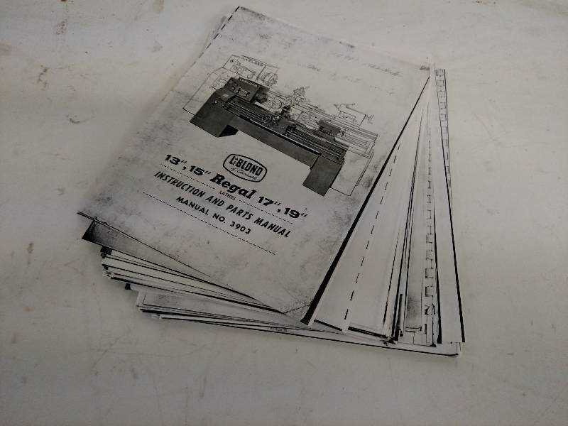
The efficient movement of workpieces during machining operations relies heavily on the mechanisms responsible for feed and screw motion. These systems ensure precise control over the positioning of the tool and material, enabling optimal results in various manufacturing processes.
Understanding the Mechanisms
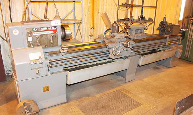
Two primary components play a crucial role in achieving smooth and accurate operation:
- Power Feed: This mechanism allows for automatic movement of the tool across the material, enhancing productivity by minimizing manual adjustments.
- Lead Screw: This component facilitates the movement of the workpiece by converting rotary motion into linear travel, enabling precise control over depth and position.
Operational Benefits
Utilizing power feed and lead screw systems offers several advantages:
- Increased efficiency through reduced manual intervention.
- Enhanced accuracy, leading to better surface finishes.
- Improved operator comfort, as less physical effort is required.
Understanding the interplay between these components is essential for optimizing machining performance and achieving desired outcomes in manufacturing tasks.
Chuck Options and Maintenance
Choosing the right gripping device for machining operations is crucial for achieving precision and efficiency. Various types of these devices offer unique features, making them suitable for different applications and materials. Understanding the options available allows users to make informed decisions based on their specific needs.
Common types of gripping devices include:
- Three-Jaw Chucks: Ideal for gripping round workpieces, providing excellent centering accuracy.
- Four-Jaw Chucks: Allow for gripping irregularly shaped items, offering greater versatility.
- Collet Chucks: Known for their ability to hold small diameter components with high precision.
- Magnetic Chucks: Useful for flat workpieces, utilizing magnetism for secure holding.
Maintaining these gripping devices is essential for optimal performance and longevity. Regular care includes:
- Inspecting for wear and tear, ensuring all moving parts operate smoothly.
- Cleaning the gripping surfaces to prevent contamination and maintain grip strength.
- Lubricating the mechanisms periodically to reduce friction and enhance operation.
- Checking alignment and calibration to ensure consistent accuracy.
By selecting the appropriate gripping mechanism and adhering to proper maintenance practices, users can enhance machining accuracy and extend the lifespan of their equipment.
Coolant System Integration Techniques
In the realm of precision machining, effective coolant management is crucial for maintaining optimal performance and prolonging tool life. Integrating a cooling system into machining setups involves various strategies to enhance fluid delivery and reduce thermal stress during operations. This section delves into key techniques for seamless integration, ensuring efficient cooling and lubrication throughout the machining process.
Key Strategies for Integration
- Optimized Delivery Mechanisms: Implementing adjustable nozzles can direct coolant precisely where needed, minimizing waste and maximizing effectiveness.
- Fluid Recycling: Employing a closed-loop system allows for the collection and purification of coolant, promoting sustainability and cost efficiency.
- Temperature Control: Utilizing chillers or heat exchangers ensures that coolant remains within ideal temperature ranges, enhancing its performance.
Maintenance and Monitoring
- Regularly inspect hoses and fittings for leaks to prevent fluid loss and maintain pressure.
- Monitor coolant concentration and pH levels to ensure optimal performance and prevent bacterial growth.
- Schedule routine cleaning of the system to eliminate debris that can hinder flow and efficiency.
