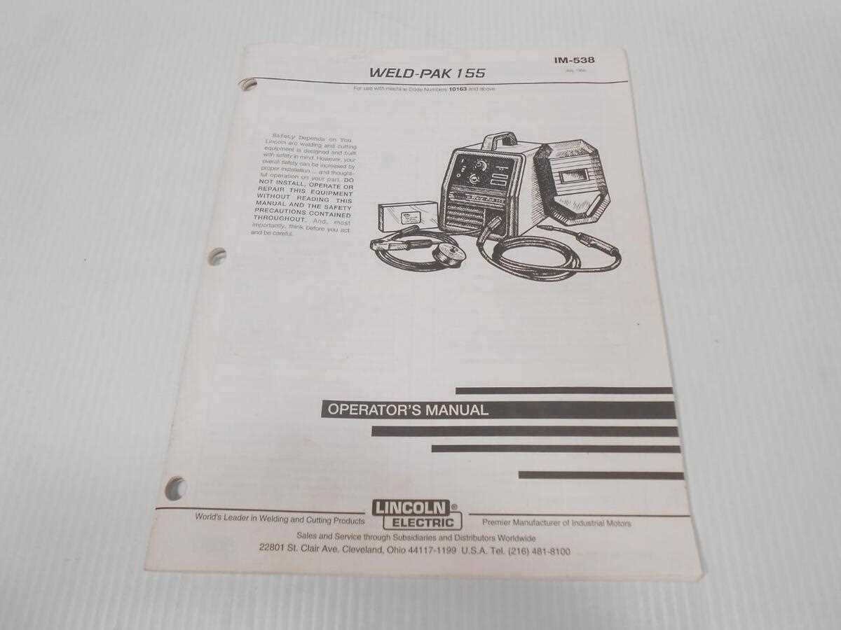
A versatile welding machine is an essential tool for both professional welders and hobbyists. Understanding the different elements that make up this tool can greatly enhance its performance and lifespan. Each component plays a critical role in ensuring smooth operation and efficiency, making it important to be familiar with the internal layout.
Whether you’re troubleshooting, performing maintenance, or seeking to optimize the use of your equipment, having a clear overview of its structure can save time and effort. Identifying key elements and their functions will empower users to handle repairs or adjustments with confidence.
By breaking down the various mechanisms, you can also ensure that each part is functioning correctly, minimizing downtime and preventing potential issues. Regular checks and understanding of these components will ensure reliable and long-lasting performance in various projects.
Overview of Lincoln Weld-Pak 155 Components
The structure of this versatile welding machine consists of several essential elements that work together to provide efficient functionality. Each component is designed to ensure optimal performance and durability, contributing to the smooth operation of the entire system. Understanding the main units and their roles can help users maintain and troubleshoot the device more effectively.
Core Elements
At the heart of the system lies the power unit, which supplies the necessary energy to perform welding tasks. Connected to this is the control panel, allowing users to adjust settings according to their needs. These two elements are crucial for managing the device’s performance, offering flexibility in various welding applications.
Supporting Mechanisms
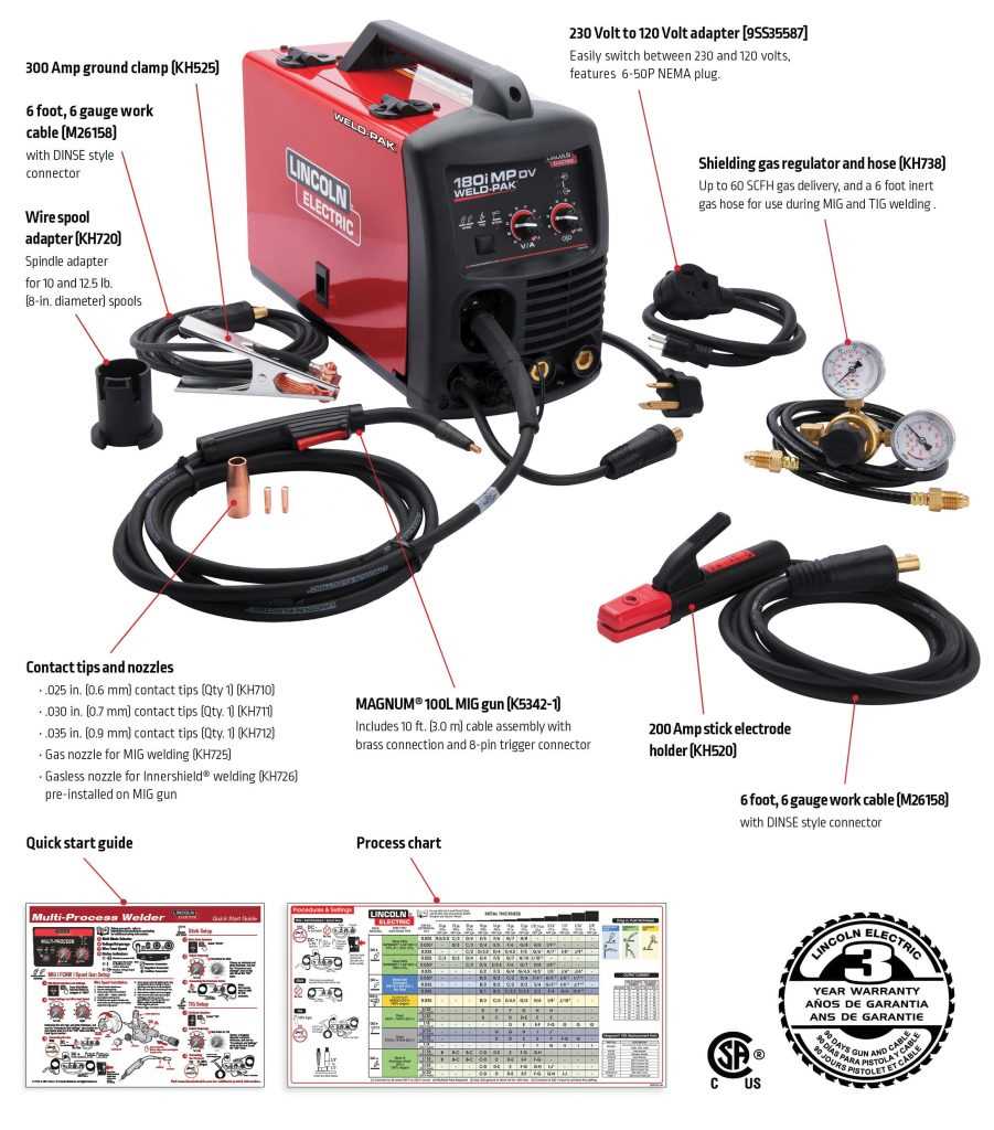
In addition to the primary units, supporting mechanisms include the wire feeding system and safety components. The wire feed ensures a steady flow of material, while safety features protect the operator during usage. These mechanisms work in harmony with the core elements, enhancing the overall safety and precision of the machine.
Main Control Panel Functionality
The control panel serves as the central hub for operating the device, offering a range of settings to manage various functions. Users can easily adjust power levels, set modes, and monitor performance through this interface. Designed for both efficiency and user-friendliness, it ensures smooth control over the equipment’s operations without needing to engage with internal components.
Key Features of the Control Panel
The panel offers intuitive controls, allowing for adjustments in voltage, current, and output settings. It also includes indicators that provide feedback on the machine’s status, helping users identify optimal operating conditions and prevent potential issues. The layout of buttons and switches is designed to ensure quick access and visibility, even in challenging environments.
Component Overview

| Component | Function |
|---|---|
| Power Switch | Turns the device on or off, ensuring energy efficiency when not in use. |
| Voltage Control | Adjusts the power output to match the requirements of the task at hand. |
| Status Indicator | Displays the current operational status, helping to track machine performance. |
Wire Feed Mechanism and Adjustments
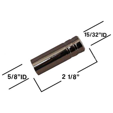
The wire feed system plays a critical role in ensuring smooth and consistent material flow during welding. A well-maintained mechanism enables seamless feeding, reducing interruptions and ensuring high-quality results. Proper calibration of the feed speed is essential to match the workpiece and welding conditions, allowing for better control and precision.
Adjustments to the feed system include modifying the tension on the drive rollers to match different wire sizes and types. Too much or too little tension can lead to problems like slipping or wire jams. It is important to regularly check and fine-tune these settings to avoid disruptions during welding.
The speed settings should also be adjusted according to the material and thickness being worked on. Fine-tuning the wire speed ensures optimal performance, reducing the chances of irregular arcs or poor weld quality.
Internal Circuit Board Layout
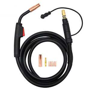
The internal layout of the circuit board is designed to manage various electrical pathways and components that ensure the machine’s proper functionality. The structure is organized in a way that each section of the board serves a specific function, contributing to the overall operation. Understanding the layout helps to identify potential areas for troubleshooting or upgrading components when necessary.
Component Placement
The placement of components on the board follows a logical arrangement, ensuring that power distribution and control signals flow efficiently. Key elements are positioned strategically to reduce interference and enhance performance, making it easier to maintain or replace parts during servicing.
Wiring and Connections
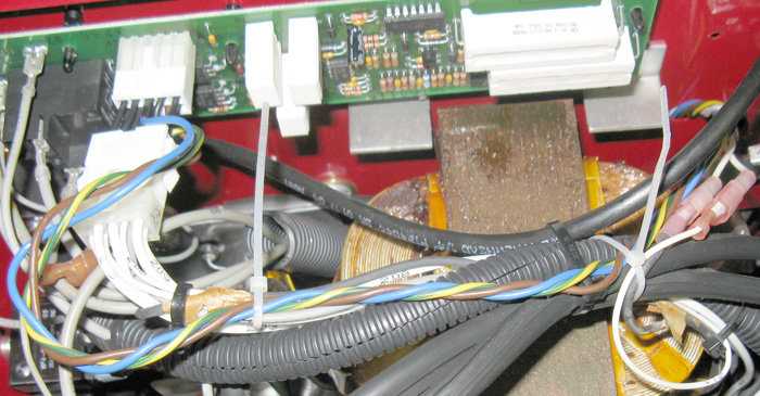
The wiring and connections on the board are neatly routed to prevent any short circuits or signal disruptions. These connections link various sections of the board, allowing different subsystems to communicate effectively and maintain the overall system integrity.
Cooling Fan Assembly and Maintenance
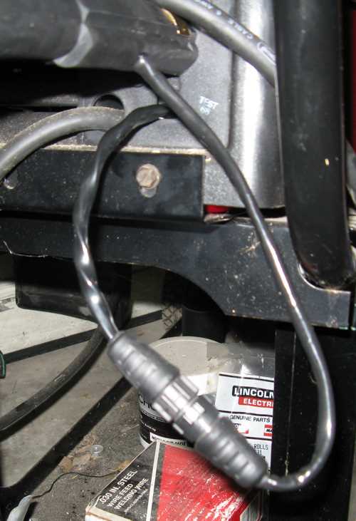
The cooling fan plays a critical role in ensuring proper ventilation during the machine’s operation. Regular maintenance of this component helps prevent overheating and ensures optimal performance. Understanding how to assemble and care for the fan can significantly extend the life of the entire unit.
Assembly Process
Assembling the cooling fan requires attention to detail to ensure proper alignment and secure attachment. Begin by ensuring all components are clean and free of debris. Carefully place the fan blades onto the designated mounting area, making sure they rotate freely. Tighten all screws firmly, but avoid over-torquing, as it can damage the mount.
Maintenance Tips
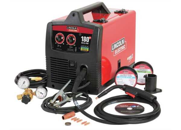
Regular inspection is key to keeping the fan in good working condition. Check for dust buildup, as it can reduce efficiency. Use compressed air to clean the fan blades and motor. Additionally, ensure the fan’s motor is lubricated if necessary, and replace any worn or damaged parts immediately to avoid further issues.
Power Cord and Switch Configuration
This section focuses on the electrical connections and control mechanisms essential for the safe and efficient operation of the device. Understanding the arrangement of the power supply and the functionality of the switch is crucial for both maintenance and troubleshooting.
Understanding the Power Supply
The power supply serves as the backbone for the device’s operation. Here are some key points regarding its configuration:
- The cord must be rated for the appropriate voltage and amperage.
- It should be securely connected to prevent any accidental disconnections.
- Regular checks for wear and damage are necessary to ensure safety.
Switch Functionality and Placement
The switch controls the flow of electricity, making its placement and functionality vital. Consider the following aspects:
- Ensure the switch is easily accessible for quick operation.
- Verify that the switch is rated for the device’s electrical load.
- Regular inspection for proper functioning helps prevent electrical hazards.
Gas Regulator and Hose Connections
The gas regulator and hose connections play a crucial role in ensuring a reliable supply of gas for various applications. Proper installation and maintenance of these components are essential for optimal performance and safety during operation.
When setting up the gas system, consider the following elements:
- Gas Regulator: This device controls the pressure of the gas coming from the cylinder, ensuring a steady flow to the equipment.
- Hoses: Flexible tubes that transport gas from the regulator to the torch or other tools.
- Connectors: Fittings that secure the hoses to both the regulator and the equipment, preventing leaks.
To ensure efficient operation, follow these guidelines:
- Check for compatibility between the regulator and the gas type.
- Inspect hoses for any signs of wear or damage before connecting.
- Ensure all connections are tight and leak-free by using soapy water to test for bubbles.
Regular maintenance and careful handling of these components will enhance the safety and longevity of the equipment.
Drive Roller Replacement Process
Replacing the drive roller is a vital maintenance task that ensures the proper functioning of the welding machine. This component plays a crucial role in feeding the wire efficiently during operations. Following a systematic approach will help you execute this replacement effectively.
Preparation Steps
- Gather necessary tools such as a wrench, screwdriver, and replacement roller.
- Disconnect the power supply to prevent any accidental activation.
- Remove any protective covers to access the drive mechanism.
Replacement Procedure
- Locate the existing drive roller within the machine.
- Loosen the fasteners holding the roller in place using the appropriate tool.
- Carefully remove the old roller from its housing.
- Position the new roller in the same orientation as the previous one.
- Tighten the fasteners securely to ensure the roller is firmly in place.
- Reattach any covers that were removed during the process.
- Reconnect the power supply and test the machine to ensure proper functionality.
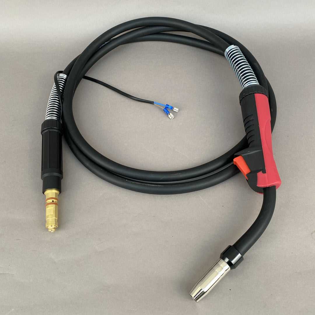
Gun and Nozzle Parts Breakdown
The effective operation of a welding apparatus relies heavily on the functionality of its components. Understanding the individual elements that make up the gun and nozzle is crucial for maintenance and optimal performance. Each piece plays a significant role in ensuring a smooth welding process, contributing to the overall efficiency of the equipment.
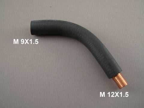
The assembly includes essential components such as the trigger, which initiates the welding operation, and the nozzle, which directs the flow of the welding material. Additionally, the contact tip serves to conduct electrical current, while the gas diffuser aids in the proper distribution of shielding gas. Other integral parts include the retaining head, which secures the nozzle, and the liner, guiding the welding wire seamlessly to the tip.
Familiarity with these components not only facilitates timely replacements but also enhances troubleshooting capabilities, leading to improved performance and longevity of the equipment. Regular inspection and maintenance of these elements are advisable to prevent malfunctions and ensure a consistent welding experience.
Transformer and Rectifier Details
The transformer and rectifier are vital components in welding equipment, playing crucial roles in the conversion and regulation of electrical energy. These elements work together to ensure a consistent power supply necessary for effective welding operations. Understanding their functions and configurations can enhance the efficiency and performance of the equipment.
Transformer Functionality
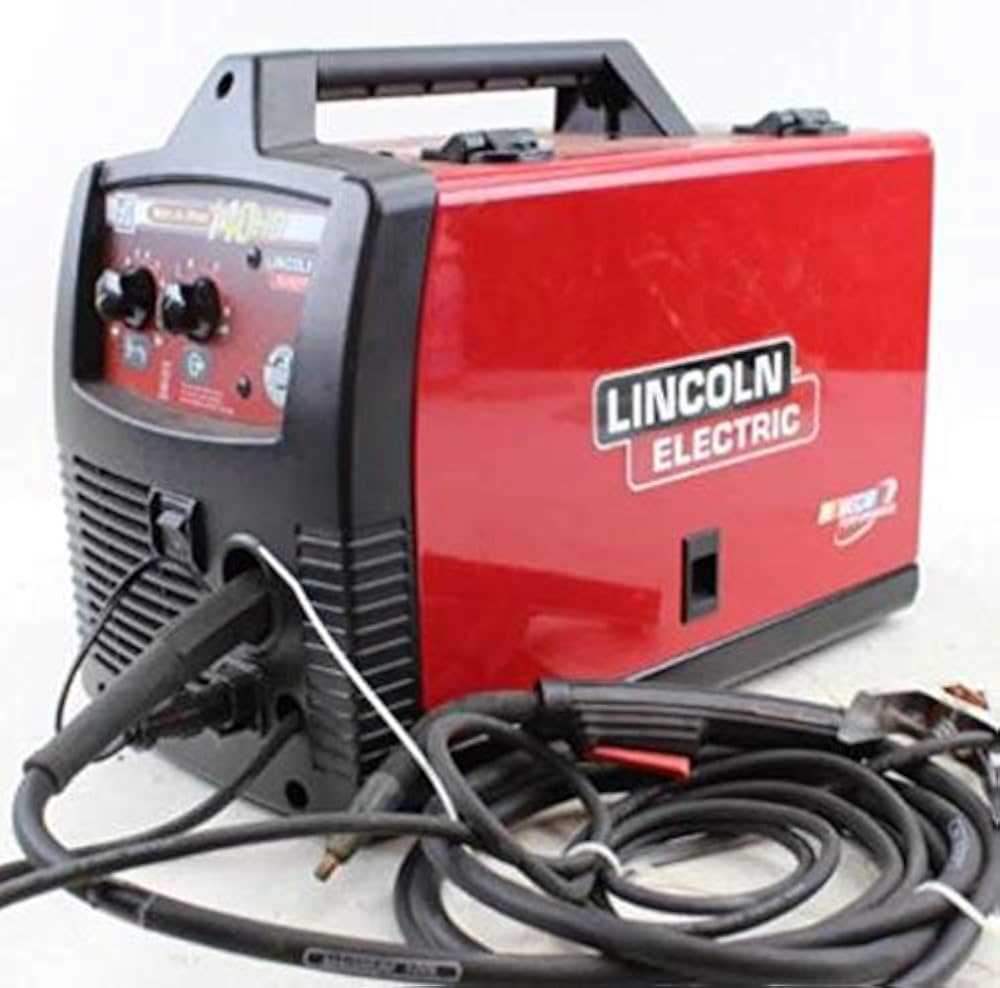
The transformer is designed to step down high voltage input to a lower voltage suitable for welding applications. It operates on the principle of electromagnetic induction, allowing for safe and efficient power transfer. The design typically includes a core made of magnetic material, which helps in directing the magnetic flux, thereby improving performance.
Rectifier Operation
The rectifier converts alternating current (AC) from the transformer into direct current (DC), which is essential for many welding processes. It employs diodes to achieve this conversion, allowing current to flow in one direction only. The output from the rectifier is characterized by smooth and consistent voltage, enhancing the quality of the welding arc.
| Component | Function |
|---|---|
| Transformer | Steps down voltage for safe use |
| Rectifier | Converts AC to DC for welding |
| Diodes | Controls direction of current flow |
Protective Housing and Exterior Parts
The protective casing and outer components play a crucial role in safeguarding the internal mechanisms of the device. These elements are designed not only for durability but also for providing ease of access to the functional parts within. A well-constructed exterior ensures that the equipment remains operational in various working environments.
Durability and Protection
Robust materials are utilized in the construction of the housing, which is essential for preventing damage from external factors. Weather resistance and shock absorption are key features that enhance the lifespan of the equipment. By shielding the sensitive internal elements, these external structures contribute significantly to the overall performance and reliability.
Accessibility and Maintenance
Easy access to the interior components is vital for maintenance and repairs. The design often includes removable panels or covers that facilitate quick inspections and servicing. Regular upkeep of these areas ensures that the device functions efficiently, minimizing downtime and extending its operational life.