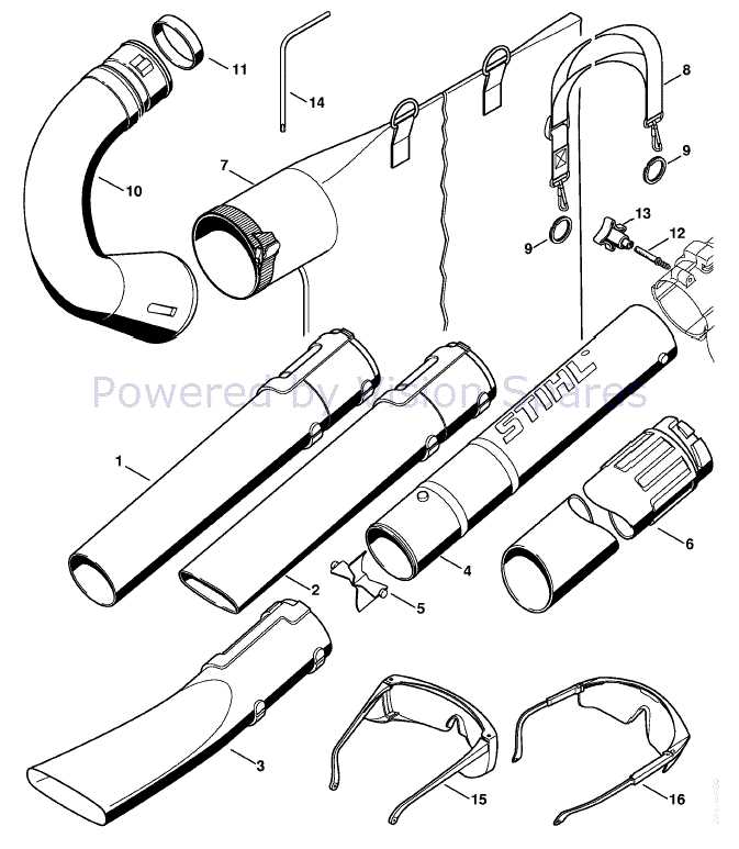
Understanding the internal structure and how various elements interact is essential for efficient maintenance and repair of outdoor equipment. This guide will walk through the key elements that make up the functionality of such devices, highlighting critical areas and connections. Whether you’re dealing with mechanical issues or just performing routine upkeep, knowing how different sections are arranged will help ensure smooth operation.
From engine performance to fuel delivery systems, each piece plays a crucial role in the overall operation. By familiarizing yourself with the arrangement
Essential Components of the Stihl BG55 Blower
Understanding the key mechanical elements is crucial for maintaining and repairing this handheld tool. Each component works together to ensure optimal performance, helping to deliver a powerful airflow. Recognizing the importance of individual parts allows for efficient troubleshooting and long-lasting operation.
Engine and Ignition System
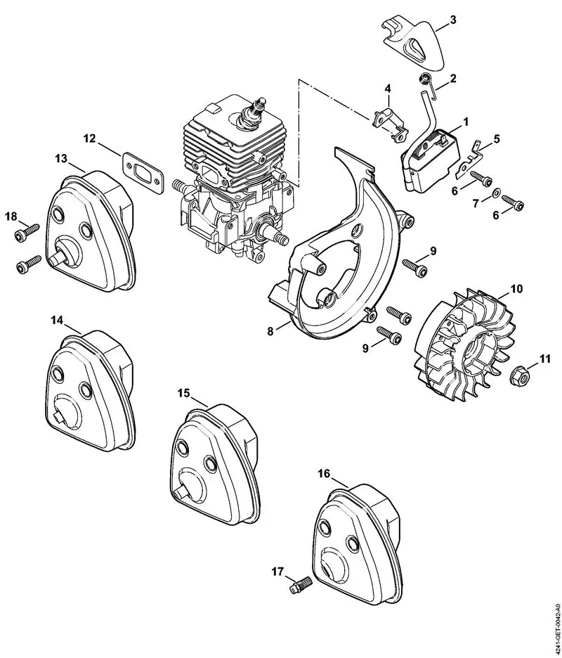
The power unit serves as the heart of the device, generating the necessary energy to drive the fan mechanism. In combination with the ignition system, it ensures a reliable start and consistent operation. Proper maintenance of this section helps avoid issues such as misfiring or loss of power.
Fan Assembly and Air Output
The fan section is responsible for creating the strong force that directs airflow through the nozzle. Made of durable materials, it efficiently handles air intake and expulsion. Keeping this part clean and free of obstructions is vital for maintaining maximum efficiency.
Key Housing and Exterior Parts
In this section, we’ll examine the crucial outer components that form the structural foundation of the equipment, offering protection and support for internal mechanisms. These elements not only provide a secure casing but also play a significant role in ensuring durability and performance in demanding environments.
Protective Casing
The casing acts as a safeguard, shielding delicate internal systems from dust, debris, and impact. Its robust design is essential for maintaining the longevity of the device, ensuring that all mechanical functions are safely enclosed while still allowing for user-friendly access to necessary sections.
Handles and Control Features
Equally important are the handles and control mechanisms, which ensure ease of operation. These components are ergonomically designed for
Internal Mechanisms for Efficient Airflow
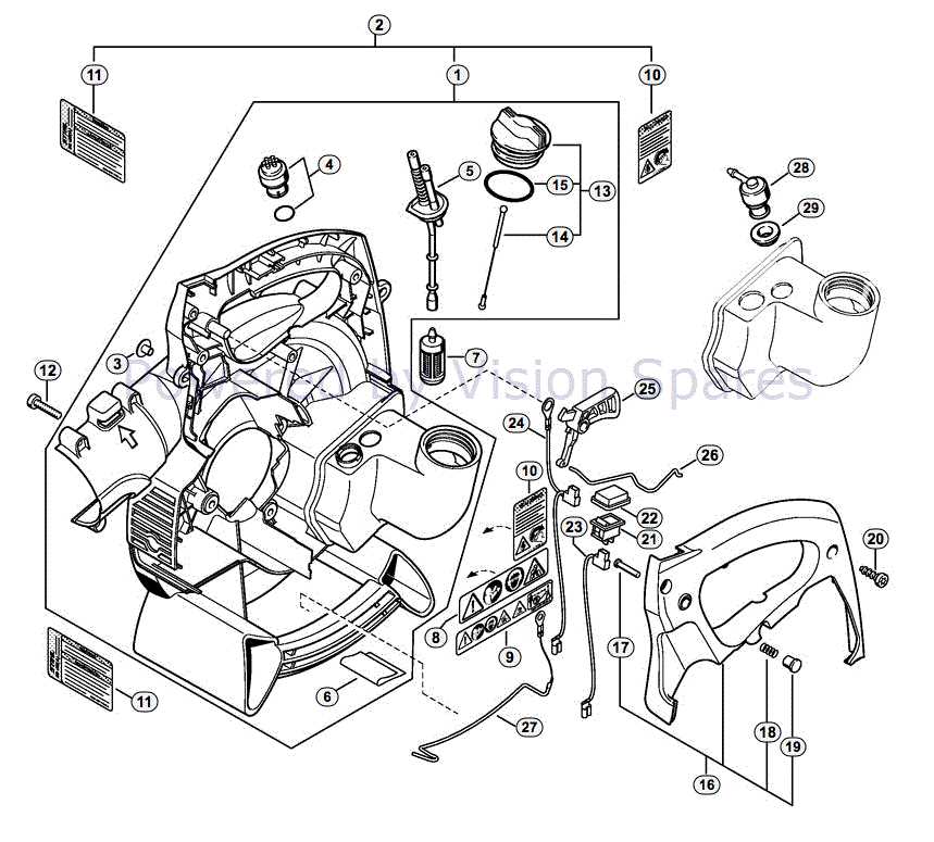
The internal structure of this equipment is designed to optimize air movement, ensuring maximum efficiency during operation. Key components work in unison to create a powerful, directed flow, allowing the machine to function smoothly even in challenging conditions. By understanding the interaction of these mechanisms, users can better maintain and troubleshoot the device for enhanced performance.
Key Components Driving Air Circulation
At the heart of the system is a powerful motor that generates the initial force. This energy is then transferred to an impeller,
Understanding the Carburetor Assembly
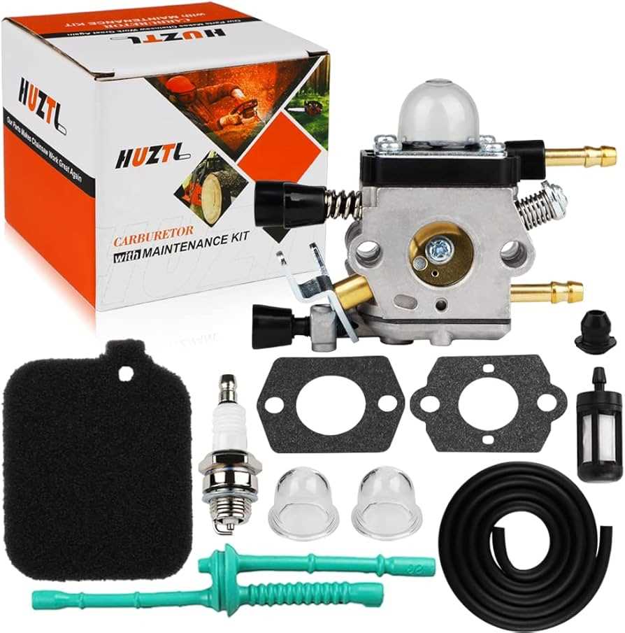
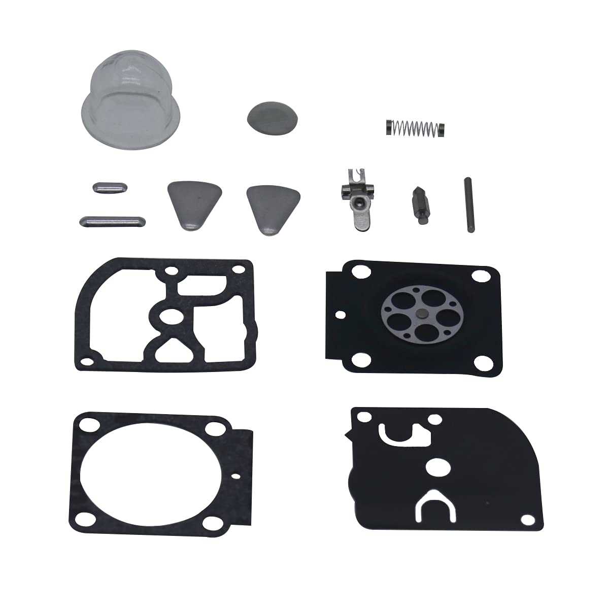
The carburetor is a critical component of any small engine, responsible for blending air and fuel to achieve optimal combustion. Without a well-functioning carburetor, the engine may experience performance issues or even fail to start. Understanding the structure and function of this assembly is key to maintaining efficiency and prolonging the lifespan of the engine.
Key Components of the Carburetor
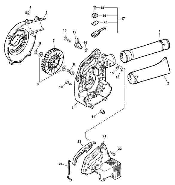
- Throttle Plate: Controls the amount of air entering the engine, adjusting speed and power output.
- Needle Valve: Regulates fuel flow into the air stream to maintain the correct air-fuel ratio.
- Choke Lever: Temporarily restricts air flow during cold starts, helping the engine ignite more easily
Ignition System: Coil and Spark Plug
The ignition mechanism is critical for ensuring the smooth operation of the engine, allowing for the precise timing of combustion. At the heart of this system are two key components: the coil and the spark plug. These components work together to generate the necessary spark that ignites the fuel-air mixture, driving the engine’s internal processes.
The coil’s primary role is to transform low voltage from the power source into a high-voltage current required by the spark plug. The spark plug then delivers this charge to the combustion chamber, where it ignites the fuel mixture, initiating the engine cycle. Proper maintenance of both components is essential for optimal engine performance.
Component Function Maintenance Tip Coil Fan and Impeller Functionality
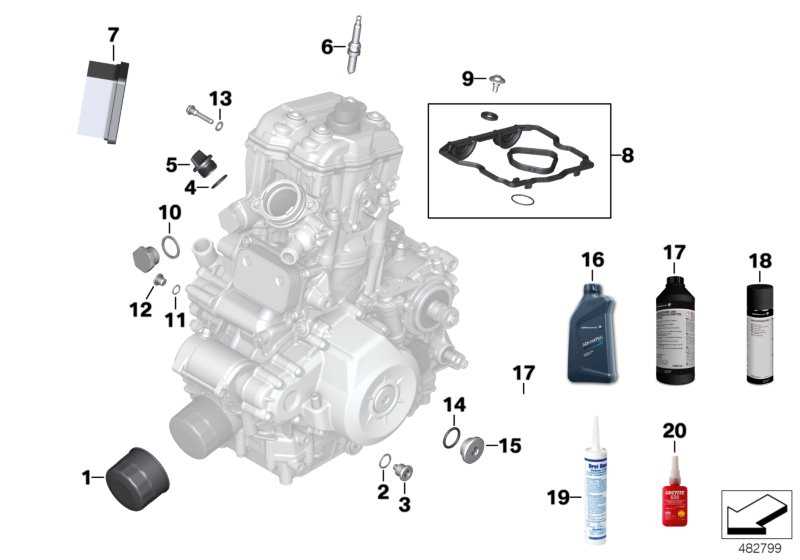
The components responsible for airflow within a handheld device play a critical role in its overall efficiency and performance. These elements work together to create a powerful stream of air, which is essential for the effective operation of the equipment. Understanding their design and interaction provides insight into how optimal airflow is achieved.
The fan and impeller are designed to maximize airflow while minimizing resistance. The fan generates movement, while the impeller directs the air with precision, enhancing the speed and force of the output. This synergy is crucial for the equipment’s ability to effectively clear debris and achieve the desired results.
Component Function Impact on Performance Fan Creates airflow Increases air velocity Impeller Directs and concentrates airflow Enhances efficiency in debris removal Housing Encases and guides airflow Reduces turbulence, improving output Proper maintenance of these components ensures sustained performance. Regular inspection and cleaning can prevent debris buildup, which may hinder airflow and reduce efficiency. Understanding the functionality of the fan and impeller is essential for users aiming to maintain optimal performance over time.
Throttle Control and Trigger Mechanisms
The efficiency of handheld outdoor equipment largely depends on the design and functionality of its control systems. These components play a crucial role in regulating engine speed and overall operation, ensuring optimal performance during use. Understanding how these mechanisms interact can enhance user experience and promote effective maintenance practices.
Throttle control is integral to managing power output, allowing the operator to adjust speed according to the task at hand. This system typically comprises a lever or trigger that connects to the engine via a cable. When engaged, it alters the airflow or fuel mixture, thus affecting engine responsiveness.
Equally important is the trigger mechanism, which facilitates precise handling and operational safety. This mechanism is designed to respond instantly to user input, providing immediate control over the equipment’s performance. Features such as safety locks or momentary switches are often incorporated to prevent accidental activation, enhancing user safety.
Regular inspection of these components is essential to ensure their longevity and reliable performance. Addressing wear and tear promptly can prevent malfunctions, ensuring that the equipment remains efficient and effective throughout its operational lifespan.
Fuel Tank and Line Connections
The fuel reservoir and associated tubing are critical components in the overall functionality of outdoor power equipment. Properly understanding the configuration and maintenance of these elements ensures optimal performance and longevity. This section delves into the structure and significance of the fuel system connections, highlighting their role in delivering the necessary fuel mixture for efficient operation.
Understanding the Fuel Tank Assembly
The fuel storage unit typically features a durable design that prevents leaks and ensures secure containment of the fuel mixture. This assembly is often equipped with a venting system that facilitates pressure regulation and prevents vapor lock. Regular inspection of the tank is essential, as wear and tear can lead to performance issues.
Connection Lines and Maintenance
Fuel lines serve as conduits, transporting the fuel from the tank to the engine. These tubes must be inspected frequently for any signs of wear, such as cracks or leaks. Maintaining clean and unobstructed lines is vital for proper fuel flow. Replacing damaged tubing promptly can prevent engine stalling and ensure efficient operation.
Air Filter Placement and Maintenance
Proper positioning and upkeep of the filtration system are crucial for optimal operation and longevity of outdoor equipment. Ensuring that the air intake remains unobstructed and clean contributes significantly to engine performance and efficiency.
Placement of the Filtration System
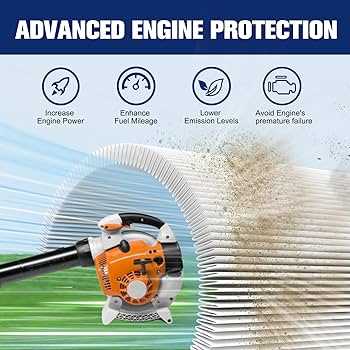
The filter should be installed in a designated compartment that is specifically designed for this component. Here are some considerations for proper placement:
- Ensure the filter is seated securely within its housing.
- Avoid any obstructions that could block airflow.
- Regularly check for signs of wear or damage that may affect placement.
Maintenance Practices
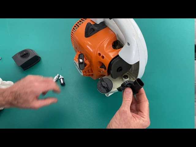
Regular maintenance of the filtration unit is essential for the effective operation of the equipment. Consider the following practices:
- Inspect the filter periodically for dirt and debris accumulation.
- Clean or replace the filter as recommended by the manufacturer.
- Ensure that the filter is properly reinstalled after cleaning or replacement to maintain efficiency.
By adhering to these guidelines, users can enhance the functionality and lifespan of their outdoor equipment.
Recoil Starter and Pull Cord System
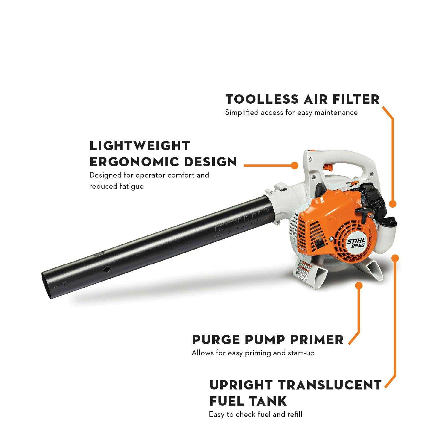
The recoil mechanism and pull cord assembly play a crucial role in the operation of handheld outdoor equipment. These components work together to initiate the engine’s start-up process, providing a reliable method to engage the motor efficiently. Understanding the functionality and construction of this system is essential for effective maintenance and troubleshooting.
Functionality of the Recoil Mechanism
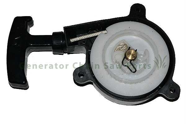
The recoil mechanism operates by storing kinetic energy when the cord is pulled. This energy is released as the cord retracts, enabling the starter pawl to engage the engine flywheel. This action turns the engine over, allowing it to start. Proper adjustment and maintenance of the recoil assembly ensure smooth operation and longevity.
Maintenance Tips for the Pull Cord Assembly
Regular inspection of the pull cord is vital to prevent unexpected failures. Signs of wear, such as fraying or breaking, should be addressed immediately to avoid further complications. Lubricating the recoil mechanism and ensuring that all components are securely fastened can enhance the efficiency of the starting system. Replacing the pull cord when necessary will ensure reliable performance during operation.
Protective Shields and Safety Features
Ensuring user safety during operation is a vital aspect of any outdoor power equipment. Various protective components are designed to mitigate risks and enhance safety while in use. Understanding these features can lead to better handling practices and overall performance.
Key Safety Elements
- Guarding Mechanisms: These shields are positioned strategically to deflect debris, preventing it from striking the operator.
- Ergonomic Design: Handles and grips are crafted to provide comfort and control, reducing the likelihood of accidents caused by slippage.
- Vibration Reduction: Integrated systems that minimize vibrations help decrease operator fatigue, allowing for longer and safer usage.
Maintenance of Safety Features
- Regularly inspect protective components for signs of wear or damage.
- Ensure that all safety mechanisms are functioning correctly before operation.
- Clean and maintain equipment to avoid blockages that may compromise safety features.