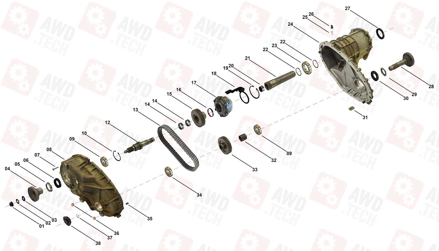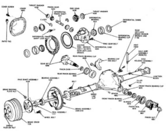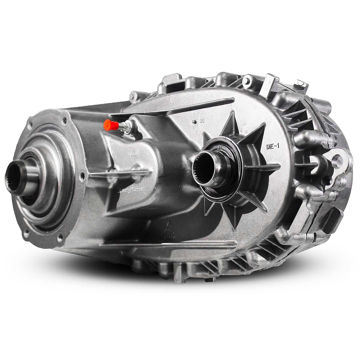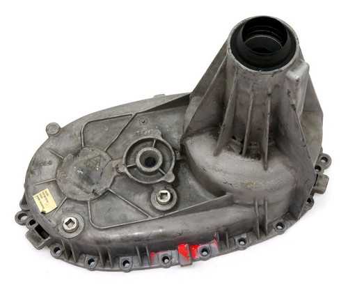
The assembly and functionality of any machinery rely heavily on a clear representation of its various elements. Such representations are essential for effective maintenance and troubleshooting, ensuring that users can easily identify each segment and its role within the larger system.
Visual guides that outline the arrangement of components play a crucial role in enhancing comprehension. By examining these illustrations, individuals can gain valuable insights into the operational dynamics of the equipment, facilitating a more efficient workflow. Furthermore, these resources often serve as a reference point during repairs and upgrades, making the understanding of each part’s interaction vital for optimal performance.
As we delve into the specifics of this topic, we will explore how these illustrative resources can assist in navigating the complexities of the machinery. This exploration will highlight the significance of clarity in technical documentation and its impact on user proficiency and confidence in handling equipment.
Importance of Parts Diagrams
Understanding the structure and composition of mechanical assemblies is crucial for efficient maintenance and repair. Visual representations of these components not only aid in identifying individual elements but also facilitate the overall comprehension of how each piece interacts within the system.
Enhancing Maintenance Efficiency
Utilizing visual guides significantly streamlines the process of upkeep. Technicians can quickly locate specific elements, reducing the time spent searching for parts during repairs. This efficiency leads to:
- Faster diagnostics of issues
- Minimized downtime of equipment
- Improved workflow in repair facilities
Facilitating Training and Knowledge Transfer
For new technicians, visual aids serve as essential educational tools. They provide clear insights into complex assemblies, enabling easier understanding of function and assembly. This knowledge transfer can result in:
- Shortened training periods
- Increased confidence in handling repairs
- Higher quality of service due to improved understanding
Main Components of Bw4485
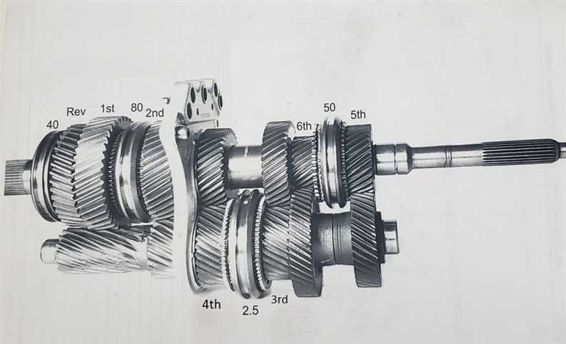
This section explores the essential elements of the device, highlighting their roles and significance in its overall functionality. Understanding these core components is crucial for effective maintenance and optimal performance.
- Frame: The structural backbone that supports and houses various elements, ensuring stability and durability.
- Power Unit: Responsible for providing the necessary energy to operate the system efficiently.
- Control Mechanism: This component manages the operation and functionality of the device, enabling user interaction.
- Transmission System: Facilitates the transfer of power and motion between components, ensuring smooth operation.
- Cooling System: Maintains optimal operating temperatures, preventing overheating and enhancing longevity.
- Safety Features: Integrated systems designed to protect users and prevent accidents during operation.
Familiarizing oneself with these components not only aids in troubleshooting but also enhances the ability to carry out routine inspections and necessary repairs.
Understanding Diagram Symbols and Labels
Interpreting graphical representations requires familiarity with various symbols and annotations used to convey specific information. These visual elements serve as a universal language, enabling individuals to comprehend complex systems efficiently. By grasping the meaning behind these icons and labels, one can enhance their understanding of the overall structure and functionality.
Symbols often represent components, while labels provide essential details regarding their characteristics or connections. Here are some common categories of symbols you may encounter:
- Geometric Shapes: Different shapes indicate various types of elements, such as squares for electrical components or circles for connectors.
- Lines: Solid lines may illustrate direct connections, while dashed lines can signify optional or conditional relationships.
- Arrows: Directional arrows indicate flow or movement, guiding users through the system’s operation.
Labels accompanying these symbols typically provide vital information, including:
- Part Numbers: Unique identifiers that specify each element.
- Specifications: Details about dimensions, materials, or performance characteristics.
- Connection Points: Indicators that show where components link together, facilitating assembly or troubleshooting.
By familiarizing yourself with these symbols and their corresponding labels, you can effectively navigate and interpret graphical representations, leading to a deeper understanding of the underlying systems.
Step-by-Step Assembly Guide
This section provides a clear and concise method for putting together the various components of the device. Following these instructions ensures a smooth and efficient assembly process, eliminating confusion and preventing common mistakes. Each stage is detailed to guide you from start to finish.
Preparation
Before starting, make sure you have all the necessary tools and materials ready. Lay out the components in an organized manner to make it easier to identify them during the assembly process.
Assembly Steps
| Step | Action |
|---|---|
| 1 | Begin by attaching the base to the frame.
Common Issues and Troubleshooting TipsRegular maintenance is essential to keep equipment running smoothly, but issues may still arise. Identifying and resolving these problems early can prevent long-term damage and ensure optimal performance. Frequent MalfunctionsOne common problem is inconsistent operation, often caused by wear and tear or improper usage. To address this, it’s important to regularly inspect components for signs of damage, such as cracks or loose connections, and replace them if necessary. Quick Solutions
If the equipment fails to operate as expected, a reset might be necessary. First, power down the unit and check for any visible blockages or obstructions. Always ensure that all parts are securely fitted and there are no external factors affecting the system. If the issue persists, consulting the manu Replacement Parts Availability
Locating the necessary components for repairs can be a simple task when you know where to search. Many retailers offer a wide selection of items that match your equipment, ensuring that you can restore functionality quickly and efficiently. It’s important to verify the compatibility of each item with your device model. This can be done by consulting online catalogs or contacting suppliers directly for further assistance. Many options are available to suit different needs and budget considerations, allowing you to choose the most suitable solutions for maintenance. Various distributors provide both original and alternative versions of required elements, giving flexibility in terms of cost and availability. Whether you’re looking for a quick replacement or seeking higher durability, there are numerous choices available in the market to meet your specific requirements. Maintenance Practices for LongevityProper care and regular maintenance are crucial to ensure the efficient operation of equipment over an extended period. By following essential upkeep routines, users can significantly extend the lifespan of their machinery, avoiding potential failures and costly repairs. Regular Cleaning and InspectionConsistent cleaning helps to prevent the buildup of dust and debris, which can hinder performance. Routine inspections allow early detection of wear and tear, enabling timely interventions before issues escalate. Paying attention to smaller components and connections ensures that everything functions smoothly. Lubrication and Adjustment
Applying the correct type of lubrication reduces friction, minimizing wear on moving parts. Regular Tools Required for Repairs
When carrying out maintenance, having the right equipment on hand is essential for efficient and successful work. Properly selected tools will help you avoid unnecessary complications and ensure smooth operation during the repair process. Basic Hand Tools
Specialized EquipmentVisual Reference for Assembly
Understanding the layout and structure of the individual components is essential for smooth and efficient assembly. A detailed visual guide allows users to see how each part fits into the overall mechanism, ensuring proper placement and functionality. Key Components OverviewThis section provides a breakdown of the primary elements, offering a visual representation to guide you through the assembly process. Each piece is clearly marked to demonstrate its position and relation to the other elements, helping to avoid confusion during installation. Step-by-Step Assembly ProcessFollow the sequence of steps presented in this guide to ensure all components are assembled correctly. With a clear visual reference, each step is easy to follow, reducing the likelihood of mistakes and ensuring that all FAQs About Bw4485 Parts
This section provides answers to common inquiries regarding the individual components and their functions within the specified model. The following list addresses key questions about assembly, maintenance, and replacements, offering clarity for users.
|
