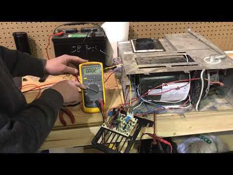
In maintaining any complex system, it’s essential to have a clear understanding of the various elements that contribute to its operation. Identifying individual elements ensures smooth functionality and aids in quick troubleshooting when necessary. This section provides insight into the essential structures that keep everything running effectively, focusing on those crucial components that are often central to the system’s performance.
By exploring detailed illustrations, we can visualize how these pieces come together, making it easier to grasp the overall structure and purpose of each element. Whether you’re dealing with routine maintenance or solving specific issues, recognizing the arrangement of key segments will streamline the process. Each aspect plays a vital role in the overall efficiency, making it important to familiarize yourself with their functions and locations.
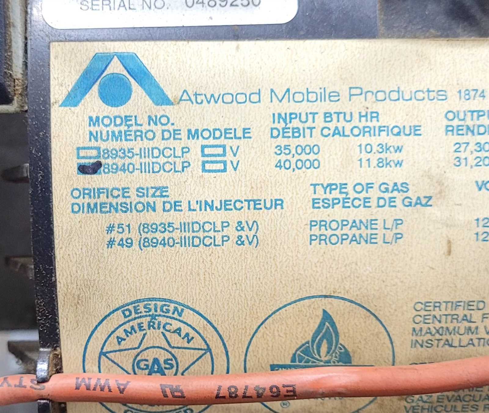
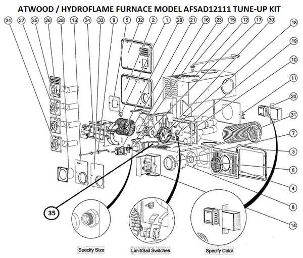
Atwood 8940-iii-dclp Parts Overview
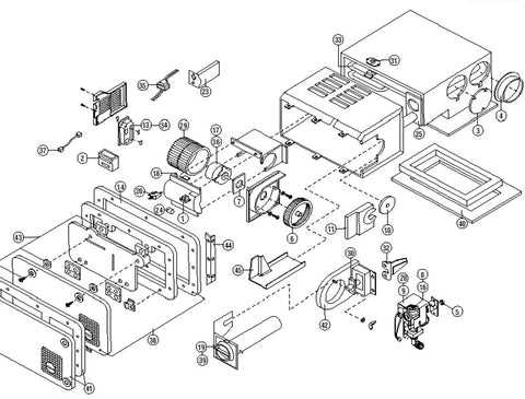
In this section, we will explore the key elements that make up the functionality of this specific heating unit. Each component plays a crucial role in ensuring the system operates efficiently and safely. Understanding these elements can help with maintenance and troubleshooting, ensuring the system remains reliable over time.
- Control Board: Regulates the entire operation, managing signals between different sections.
- Blower Motor: Circulates air to maintain proper temperature within the system.
- Ignition System: Ensures proper startup and flame control during heating cycles.
- Heat Exchanger: Transfers heat efficiently, contributing to overall performance.
- Safety Sensors: Monitors the system to prevent overheating
Key Components of the 8940-iii-dclp
The system is built from several integral elements, each contributing to its functionality and efficiency. Understanding these elements is essential for maintaining proper operation and ensuring longevity. In this section, we will explore the main functional units that form the core of the device, emphasizing their role and how they interact with one another.
Main Functional Units
One of the most critical sections includes the power management component, which ensures a stable energy flow throughout the entire system. This part works closely with other control mechanisms to regulate performance, providing balance and security under various conditions.
Control and Regulation
Another important unit is the monitoring and adjustment mechanism, which allows the user to fine-tune settings. It enhances the overall user experience by giving precise control over the operational parameters, ensuring smooth
Exploring the Wiring Diagram of the Unit
The electrical layout of a device can reveal essential information about its internal structure and functionality. Understanding how different connections interact ensures that the system operates safely and efficiently. A detailed study of the wiring configuration allows one to identify key components and their relationships within the circuit, enabling more effective troubleshooting and maintenance.
- Electrical paths and connections
- Key components involved in the flow
- Safety measures in place within the system
By carefully examining the arrangement of wires and their respective terminals, one can grasp the overall design and ensure correct installations or repairs. This exploration is crucial for those handling the technical aspects of the unit, providing a foundation for understanding its electrical workings.
Understanding the Circuit Board Layout
Comprehending the structure of a circuit board is essential for anyone working with electronic components. It involves recognizing the arrangement of various elements that ensure the smooth functioning of a device. The organization and placement of these components play a key role in determining how signals and power flow through the system.
Each section of the board is designed for specific tasks, and understanding how they interconnect is crucial for troubleshooting or optimizing performance. By observing the paths and connections, one can gain insights into the operational logic and control mechanisms within the system.
Ignition System and Its Functions
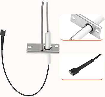
The ignition system plays a crucial role in the operation of many heating devices, ensuring the controlled combustion process. It is responsible for starting the unit safely and efficiently, delivering power at the right time to ignite the fuel. A properly functioning ignition system helps maintain reliable performance and reduces the risk of malfunctions during use.
The ignition process typically involves several components working together to create a spark or heat source, initiating the combustion necessary for the system to function. Below are the primary elements involved in the ignition process:
- Igniter: Generates the spark or heat needed to ignite the fuel.
- Control board: Manages the ignition sequence and ensures proper timing of each step.
- Safety sensors: Detect potential issues such as overheating or improper
Heat Exchanger Role in the Device
The heat exchanger is a crucial component in various systems, facilitating the transfer of thermal energy between two or more fluids. Its primary function is to improve efficiency by allowing heat to be exchanged without the fluids mixing. This process is essential in maintaining optimal operating temperatures and enhancing overall performance.
Functionality and Benefits
In any system where thermal management is necessary, the heat exchanger plays a vital role. Key functionalities include:
- Enhancing energy efficiency by recovering waste heat
- Regulating fluid temperatures to ensure stable operation
- Minimizing the risk of overheating, which can lead to equipment failure
- Improving system longevity by reducing thermal stress on components
Types of Heat Exchangers
Different types of heat exchangers serve various applications. Some common types are:
- Shell and tube exchangers
- Plate exchangers
- Air-cooled exchangers
- Double-pipe exchangers
Each type has its specific advantages and is chosen based on the requirements of the system, including space constraints, desired efficiency, and the nature of the fluids involved.
Fan Motor and Ventilation Mechanism
The functionality of a cooling system heavily relies on its fan motor and the associated airflow components. These elements work in unison to ensure effective ventilation, contributing to optimal performance and comfort within enclosed spaces.
The fan motor serves as the core component responsible for generating airflow. Its reliable operation is crucial for maintaining a consistent temperature and enhancing air circulation. Here are some key aspects of the fan motor and ventilation mechanism:
- Motor Type: Various motor types are available, each offering unique benefits in terms of efficiency and noise levels.
- Airflow Direction: Properly designed systems allow for adjustable airflow direction, enhancing versatility in air distribution.
- Speed Settings: Multiple speed settings enable users to control airflow intensity based on specific needs.
- Power Consumption: Energy-efficient models minimize power usage while providing adequate ventilation.
- Maintenance: Regular upkeep is essential for prolonging the lifespan of the motor and ensuring optimal performance.
Understanding the interplay between the fan motor and ventilation components is vital for troubleshooting and enhancing system performance. Adequate ventilation contributes to a healthier environment by promoting air exchange and reducing humidity levels.
Gas Valve Configuration and Safety Features
The configuration of gas valves plays a crucial role in the overall functionality and safety of heating systems. These components are designed to control the flow of gas, ensuring efficient operation while minimizing risks associated with gas leaks and pressure fluctuations. Understanding the design and safety mechanisms involved in gas valve systems is essential for both installation and maintenance.
Design Aspects of Gas Valves
Gas valves are typically constructed with multiple functionalities in mind. They feature adjustable settings that allow for precise control of gas flow rates. This adjustability is vital for optimizing performance in various heating applications. Additionally, many models incorporate built-in safety features such as pressure relief mechanisms and automatic shut-off capabilities, which activate in the event of irregularities, ensuring safe operation.
Importance of Safety Features
Safety features in gas valve systems are paramount for preventing accidents and ensuring user protection. These components often include sensors that detect gas leaks and trigger alarms or shut-off procedures. Regular inspection and maintenance of these safety elements are critical to maintain their effectiveness. Properly configured gas valves not only enhance performance but also provide peace of mind to users, ensuring a secure environment for operation.
Burner Assembly: Structure and Maintenance
The burner assembly is a crucial component in heating systems, responsible for producing and managing flames for optimal performance. Understanding its structure and regular upkeep is essential for ensuring safety and efficiency in operation. This section will delve into the key elements of the assembly and the best practices for maintenance.
Structure Overview
The burner consists of several integral parts, including the combustion chamber, ignition mechanism, and fuel delivery system. Each component plays a vital role in the overall functionality, allowing for effective heat generation. Proper alignment and functionality of these elements are paramount for safe operation.
Maintenance Recommendations
Routine inspections and cleaning are fundamental to prolonging the life of the burner assembly. Regularly checking for blockages, wear, or damage ensures that the system operates efficiently. It is advisable to replace worn components promptly and to follow the manufacturer’s guidelines for specific maintenance intervals.
Safety Considerations
Safety should always be a priority when handling heating systems. Ensure that the burner assembly is disconnected from the power source during maintenance. Utilizing appropriate safety gear and following standard operating procedures can mitigate potential hazards.
Thermostat Settings and Controls Overview
The regulation of temperature within various systems is crucial for maintaining optimal performance and comfort. Understanding the functions and adjustments of temperature management tools allows users to effectively control their environment, enhancing efficiency and convenience. This section delves into the various settings and controls available for temperature regulation devices.
Key Features of Temperature Control Devices
Temperature regulation tools are equipped with several essential features that enhance user experience. These may include:
- Digital display for precise temperature readings
- Adjustable settings for personal preferences
- Programmable schedules for automatic adjustments
- Remote access for convenience
Common Temperature Settings
Adjusting the temperature management device can be achieved through various settings, including:
- Heating mode for warmth during colder seasons
- Cooling mode for comfort in warmer climates
- Fan-only mode to circulate air without altering temperature
- Energy-saving settings to reduce consumption
Troubleshooting Common Electrical Issues
Addressing electrical problems can often seem daunting, yet a systematic approach can simplify the process. Common challenges include issues with power supply, faulty connections, and malfunctioning components. Understanding the symptoms and potential causes is crucial for effective resolution.
Begin by examining the power source to ensure it is functioning properly. Check for blown fuses or tripped circuit breakers that may interrupt the flow of electricity. If power is consistent, inspect all connections for signs of wear or damage, as loose or corroded terminals can lead to inadequate performance.
In addition to these checks, it’s important to test individual components for functionality. Use a multimeter to assess whether parts are operating within their specified ranges. Regular maintenance and inspections can prevent many issues from escalating, ensuring reliability and longevity of the electrical system.
Replacement Parts and Installation Guide
This section provides essential information on components needed for maintenance and repair, along with guidance for proper installation procedures. Understanding these elements is crucial for ensuring optimal performance and longevity of your system.
When seeking replacements, it is important to identify the specific items that require attention. Below is a table listing commonly used components and their respective descriptions.
Component Name Description Fuel Pump Responsible for supplying fuel to the burner assembly. Ignition Module Controls the ignition process to ensure proper combustion. Heating Element Generates heat for effective operation. Control Circuit Board Manages the overall functionality and settings of the system. To successfully replace any component, follow these general steps: ensure power is disconnected, remove the faulty item, and carefully install the new piece. It is advisable to consult the user manual for specific instructions tailored to your model to prevent any mishaps during the process.
Maintaining the 894
Proper upkeep of your appliance is essential for ensuring its longevity and optimal performance. Regular maintenance can prevent potential issues and enhance efficiency, allowing for a smoother operation over time. Understanding the key components and their functions will enable users to effectively manage maintenance tasks.
Routine Inspection
Conducting frequent checks on the unit is crucial. Look for signs of wear or damage in essential elements, ensuring they are functioning correctly. This proactive approach helps identify minor issues before they escalate into major problems, saving time and resources.
Cleaning Procedures
Keeping the appliance clean is fundamental to its operation. Regularly remove any accumulated debris or contaminants that may hinder performance. Utilize appropriate cleaning agents to maintain the surfaces without causing harm to the materials. A clean unit not only performs better but also has an extended lifespan.