
The detailed representation of machinery internals plays a crucial role in maintaining and repairing various equipment. With a clear overview of how different elements are connected, it becomes easier to troubleshoot and ensure smooth operation of the system.
A carefully designed schematic allows users to identify key elements within the equipment and understand their interrelation. This visualization not only aids in the correct installation but also ensures that replacements and upgrades can be performed accurately and efficiently.
In this section, we will explore the arrangement of essential components, shedding light on how they function together to deliver optimal performance. By understanding this structure, users can navigate the complexities of machinery maintenance with greater confidence and precision.
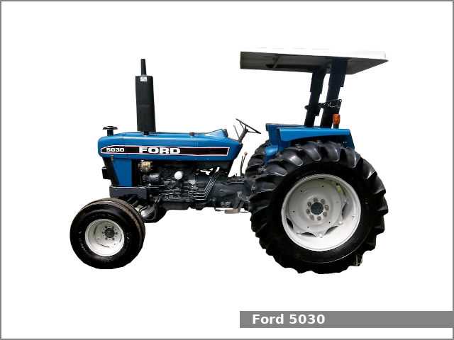
Ford 5030 Tractor Parts Diagram
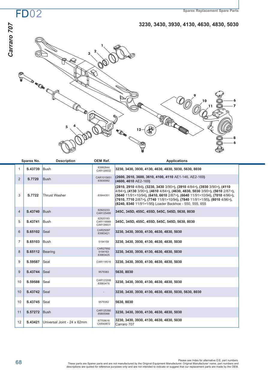
The mechanical framework of this agricultural machine is built from an intricate assembly of essential components. Each section plays a vital role in ensuring the smooth operation of the equipment, from energy conversion to power transmission, enabling the device to perform its designated tasks efficiently.
Key Components Overview
Several critical elements are interconnected to form the foundation of this system. These elements include control units, propulsion mechanisms, and support structures, all working in harmony to maintain the device’s overall functionality. Proper maintenance and replacement of these elements are crucial for long-term use.
Understanding the Layout
The physical arrangement of these elements follows a logical structure designed for optimal performance. A clear understanding of their positioning can greatly assist in troubleshooting and servicing, as each part is placed to complement the machine’s overall design, ensuring durability and reliability.
Identifying the Main Components

Understanding the structure of mechanical systems involves recognizing essential elements that contribute to their overall functionality. By identifying key elements, one can better grasp how each part works together to ensure efficient performance.
Key Structural Elements
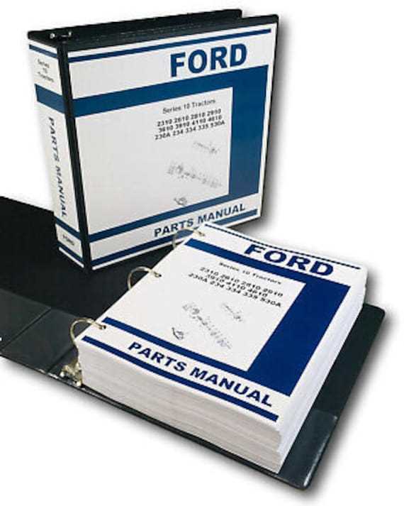
- Power unit: Provides the necessary force to drive the system.
- Transmission system: Transfers energy between components, enabling movement.
- Control mechanisms: Allow the operator to adjust and manage the system’s functions.
Auxiliary Components
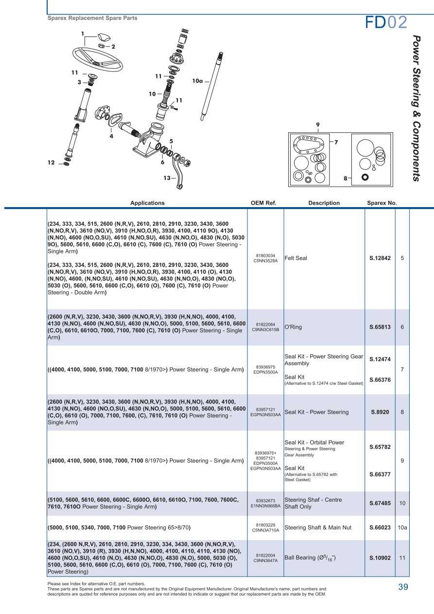
- Hydraulic system: Supports lifting and maneuvering tasks.
- Cooling system: Maintains optimal temperature during operation.
- Electrical connections: Power various auxiliary functions and lighting.
Understanding the Engine Layout
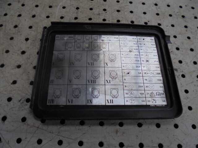
The organization of the engine system plays a crucial role in ensuring efficient operation and longevity. By examining the various elements that make up this configuration, one can gain a deeper appreciation of how each part contributes to the overall performance of the machine. Proper alignment and integration of these components are essential for smooth functionality and effective power delivery.
Cylinders, the core of the system, form the heart of the operation, where power is generated. These are supported by various auxiliary systems such as the cooling mechanism and fuel injectors, which ensure optimal performance and prevent overheating or energy loss. Each element works in unison to achieve maximum efficiency.
At the forefront of the setup is the ignition system, a critical player that initiates the power cycle. The layout also includes key passages for air intake and exhaust, which regulate pressure and contribute to smooth power output. Maintaining a balanced configuration is vital to the engine’s longevity and performance.
Hydraulic System Connections Overview
The hydraulic system plays a critical role in the overall functionality, providing the necessary force to operate various mechanisms. Understanding the way hydraulic pathways are arranged is essential for ensuring efficient operation and preventing malfunctions.
Key Components and Flow
The system is composed of interconnected components that work together to direct fluid under pressure. The pump, valves, and actuators collaborate to transfer energy, powering different functions. Each segment of the network must be properly connected to ensure a smooth flow of hydraulic fluid and reliable operation.
Maintaining Optimal Connections
Proper maintenance of hydraulic connections is vital for consistent performance. Regularly checking for leaks, ensuring secure fittings, and keeping the system free from contaminants can significantly extend the lifespan of the system. Neglecting these factors can lead to reduced efficiency and possible damage to other components.
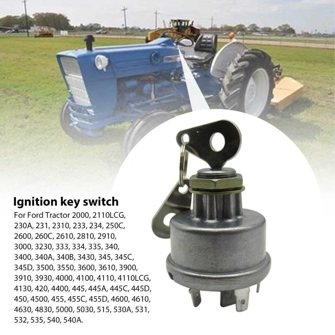
Electrical Wiring and Circuit Paths
The arrangement of electrical connections and pathways plays a critical role in ensuring smooth energy flow across various components. Each connection in this network allows current to travel effectively, enabling different systems to operate in harmony. A clear understanding of how these elements work together ensures that the design is reliable and efficient.
Key Components in Wiring
In any electrical system, wires and connections must be carefully chosen based on their capacity to handle voltage and current. Conductors, insulators, and connectors all serve distinct roles in facilitating safe and reliable transmission of energy through circuits.
Optimizing Circuit Paths

By strategically arranging the paths for electrical flow, potential energy losses can be minimized. Ensuring a direct and well-insulated route for electricity reduces inefficiencies and enhances the overall performance of the system. Proper planning and maintenance are essential to keep these pathways functioning optimally.
Brake System Parts Breakdown
The braking mechanism is essential for ensuring safety and control in any vehicle. By understanding the various components involved, one can better grasp how this system functions to provide reliable stopping power. Each element works in harmony, allowing the machine to perform effectively under different conditions.
- Brake Pedal: The operator’s control point, transmitting pressure through the system to engage the brakes.
- Hydraulic Lines: These channels transfer brake fluid, converting foot pressure into mechanical force that slows down the vehicle.
- Master Cylinder: The reservoir that supplies hydraulic fluid and ensures even distribution when the brake is applied.
- Brake Drums or Discs: These are friction surfaces where the braking action occurs, reducing the vehicle’s speed or bringing it to a stop.
- Brake Pads or Shoes: Components that press against the drum or disc, creating the necessary friction to slow down the machine.
Each part plays a critical role in maintaining proper braking performance, ensuring the vehicle can stop safely and efficiently under different working conditions.
Transmission Structure and Components
The mechanism responsible for controlling the movement of heavy machinery is complex and consists of multiple interconnected elements. It ensures the smooth transfer of energy from the engine to the wheels, providing both power and speed regulation. Understanding how this system operates is crucial for maintaining efficiency and preventing breakdowns.
Gear Sets are central to the operation, allowing the operator to choose the appropriate level of torque and speed. These sets work in harmony with shafts and clutches to manage the flow of power, adapting to different terrain conditions and workloads.
Additionally, bearings and seals play a vital role in reducing friction and ensuring the long-term durability of the system. Each component is essential for maintaining optimal performance and should be inspected regularly to avoid wear and tear.
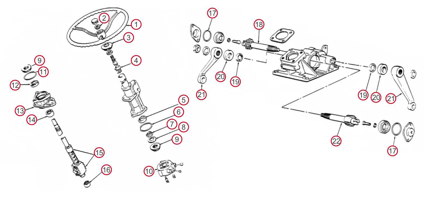
Steering Mechanism Detailed Diagram
The control system responsible for changing the direction of the vehicle is a crucial part of its overall functionality. Understanding how this system operates helps in diagnosing issues and optimizing its performance. This section focuses on the intricate network of components involved in the directional control, exploring their roles and interactions.
Main Components and Functions
The steering mechanism consists of several interconnected elements, each contributing to the smooth rotation and alignment of the wheels. The key components include the steering wheel, shafts, and joints, all working together to transmit the driver’s input to the front wheels. Ensuring proper alignment and functioning of these elements is essential for safe operation.
Key Points of Connectivity
Another important aspect is the linkage between the steering components and the wheel assembly. Precision in these connections ensures that every movement from the steering wheel is accurately reflected in the vehicle’s direction. Routine inspections of these connections can prevent potential mechanical failures.
Fuel System Parts and Configuration
The fuel delivery network is essential for the efficient operation of any engine. This system ensures that fuel is properly transported from the storage tank to the combustion chamber, where it is mixed with air and ignited. A well-designed fuel arrangement enhances performance, fuel efficiency, and overall engine reliability.
Key components of this assembly typically include the fuel tank, which stores the fuel; the fuel pump, responsible for moving the liquid; and the fuel filter, which removes impurities to protect engine integrity. Additionally, the fuel injectors play a vital role in delivering the correct amount of fuel directly into the combustion chamber, ensuring optimal mixing with air.
Understanding the layout and function of each element within the fuel system is crucial for maintenance and troubleshooting. Regular inspections and timely replacements of worn components can prevent performance issues and extend the lifespan of the engine.
Cooling System Pathways and Components
The cooling mechanism in agricultural machinery is vital for maintaining optimal operating temperatures. This system ensures that the engine does not overheat while providing efficiency and longevity. A thorough understanding of the pathways and elements involved in this system is essential for effective maintenance and troubleshooting.
Key components of the cooling mechanism include:
- Radiator: Responsible for dissipating heat from the coolant.
- Water Pump: Circulates the coolant through the engine and radiator.
- Thermostat: Regulates the temperature by controlling coolant flow.
- Coolant Hoses: Transport coolant between the engine, radiator, and other components.
- Expansion Tank: Maintains the coolant level and allows for expansion.
Understanding how these elements interact within the system is crucial for diagnosing issues. Regular inspection and maintenance of each component can prevent overheating and ensure efficient operation.
Wheel and Axle Assembly Breakdown
The wheel and axle assembly serves as a crucial component in vehicles, playing a vital role in mobility and load distribution. Understanding the intricacies of this assembly is essential for maintenance and troubleshooting. This section will delve into its structure, function, and common issues faced in operation.
Components of the Assembly

The assembly consists of various key elements, each contributing to its overall performance. Below is a list of the main components:
- Wheel Hub: The central part that connects to the axle.
- Axle Shaft: A rod that transfers power from the engine to the wheels.
- Bearings: Reduce friction and support the rotating parts.
- Brake Components: Essential for slowing down or stopping the vehicle.
- Tires: Provide traction and absorb shocks during operation.
Common Issues and Maintenance
Regular maintenance of the wheel and axle assembly can prevent serious malfunctions. Here are some common problems and suggested solutions:
- Worn Bearings: Replace bearings if they produce noise or show signs of damage.
- Brake Wear: Inspect and replace brake pads and discs as necessary.
- Alignment Issues: Regularly check alignment to ensure even tire wear and proper handling.
- Leaking Seals: Replace any seals that show signs of leaking to prevent dirt and debris from entering.