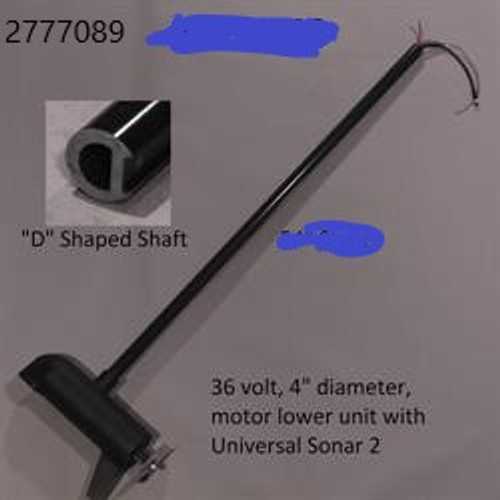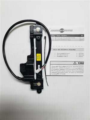
When it comes to navigating the water with precision and control, understanding the essential mechanical elements of your equipment is crucial. The efficient operation of these systems depends on how well each component is designed and maintained over time. A clear understanding of the device’s structure will help ensure its longevity and optimal performance.
In this section, we will take a closer look at the different mechanical parts that work together to deliver smooth functionality. Each piece plays a vital role in ensuring seamless operation, from the electrical elements that power the system to the hardware that holds it together.
Maintaining these elements is key to achieving maximum efficiency, and proper care will help prevent wear and tear. This detailed breakdown will assist in identifying the specific pieces and their functions, providing a helpful reference for repair or replacement.
Overview of Key Components
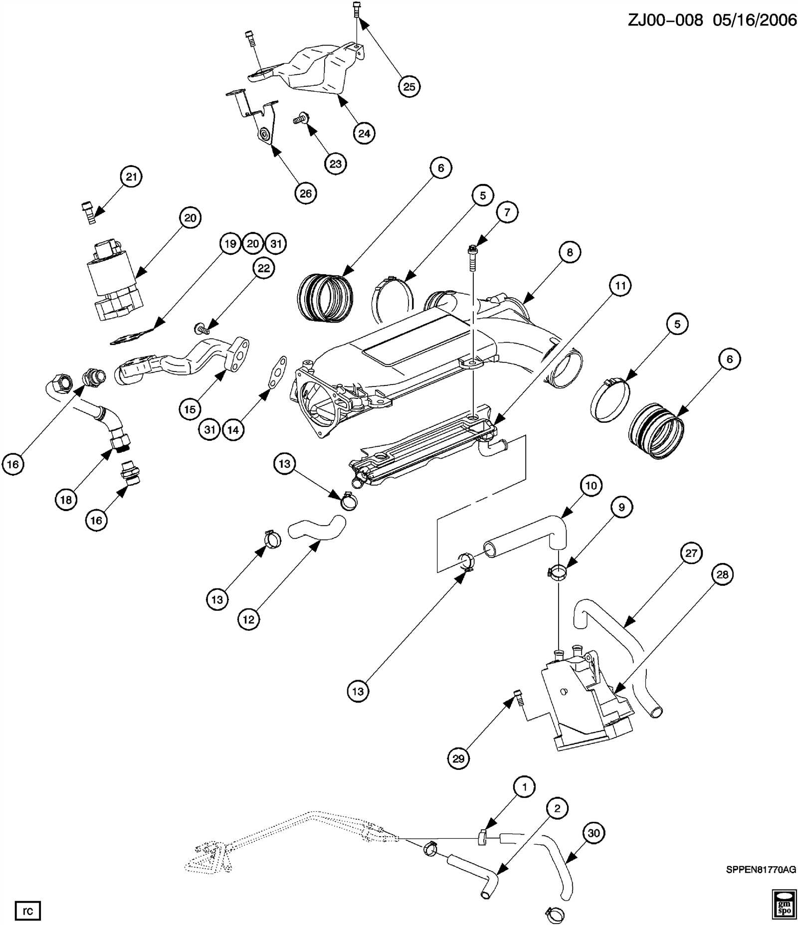
In this section, we will explore the main elements of a high-performance trolling motor system. Understanding these critical components ensures optimal functionality and ease of maintenance.
- Motor Unit: This is the powerhouse responsible for driving the system, providing thrust and ensuring smooth navigation through various water conditions.
- Control Head: The central unit where all steering commands are processed. It allows users to guide the motor efficiently, adapting to different terrains and water currents.
- Shaft: A durable component that connects the motor to the propeller. It is designed to withstand significant stress and ensures stability during operation.
- Propeller: The blade that moves the boat through the water. It’s crafted for minimal drag and maximum propulsion, ensuring efficient movement.
- Mounting Bracket: A sturdy fixture that secures the motor to the boat, providing stability and support during operation and transportation.
- Steering Mechanism: This feature allows precise maneuverability, ensuring that the motor responds quickly and accurately to user inputs.
Each of these components plays a vital role in ensuring the motor operates smoothly and effectively in different environments.
Exploring the Trolling Motor’s Internal Mechanisms
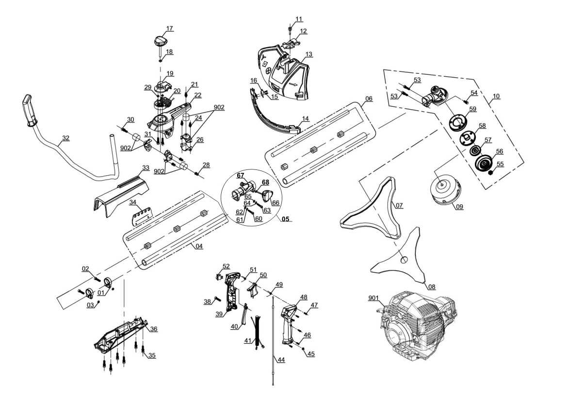
Understanding the inner workings of a trolling motor is essential for anyone looking to maintain or optimize its performance. The motor consists of various components that work in unison to ensure smooth operation on the water. Familiarizing oneself with these mechanisms can help in troubleshooting issues or performing basic repairs.
| Component | Function | |||||||||||||||||||||||||||||||||||||
|---|---|---|---|---|---|---|---|---|---|---|---|---|---|---|---|---|---|---|---|---|---|---|---|---|---|---|---|---|---|---|---|---|---|---|---|---|---|---|
| Propeller | Responsible for generating thrust by spinning in water, propelling the boat forward. | |||||||||||||||||||||||||||||||||||||
| Control Head | Houses the controls and electronic circuits that manage motor speed and steering. | |||||||||||||||||||||||||||||||||||||
| Shaft | Connects the motor housing to the control head, allowing power transmission. | |||||||||||||||||||||||||||||||||||||
| Motor Housing | Encases the motor and protects it from water damage, also holding the necessary electrical components. | |||||||||||||||||||||||||||||||||||||
| Component | Symptoms of Issues | Recommended Actions |
|---|---|---|
| Motor Assembly | Unusual noises, reduced power output | Inspect wiring and connections; clean any debris |
| Control Module | Erratic behavior, unresponsive controls | Reset system; check for software updates |
| Battery System | Short run time, overheating | Examine battery connections; ensure proper charging cycles |
Proactive Maintenance Strategies
Implementing regular inspection routines can significantly reduce the risk of failure. Establishing a schedule for checking vulnerable components ensures that any emerging issues are addressed promptly, thereby enhancing the overall reliability of the system.
Replacement Guide for Minn Kota Ultrex 112 Parts
Maintaining and replacing components of your propulsion system is crucial for ensuring optimal performance on the water. Understanding how to identify and source suitable replacements can greatly enhance your boating experience. This guide provides valuable insights into the various elements of your system, helping you make informed decisions when it’s time to replace any of its parts.
Before embarking on your replacement journey, it’s essential to familiarize yourself with the key components. Below is a helpful table that outlines common elements along with their respective functions and suggested maintenance tips.
| Component | Function | Maintenance Tips |
|---|---|---|
| Motor | Drives the propeller for movement | Regularly inspect for corrosion and ensure it’s securely mounted |
| Propeller | Propels the boat through water | Check for damage and clean regularly to maintain efficiency |
| Control System | Allows for steering and speed adjustments | Test responsiveness and keep connections clean |
| Batteries | Supplies power to the motor | Monitor charge levels and clean terminals to prevent build-up |
When selecting replacements, it’s important to consider compatibility with your specific model. Always refer to your user manual or consult with a knowledgeable supplier to ensure you’re acquiring the right components for seamless integration.
Where to Source Authentic Replacement Components
Finding genuine components for your equipment is essential for maintaining performance and longevity. When seeking replacements, it’s crucial to consider reliable sources that ensure authenticity and quality. This section explores various avenues where you can obtain the necessary items to keep your device in optimal condition.
Official Manufacturers and Distributors

The most dependable source for obtaining authentic components is through official manufacturers or their authorized distributors. They offer original items designed specifically for your model, ensuring compatibility and durability. It is advisable to visit their official websites or contact customer service for guidance on acquiring the right components.
Reputable Online Retailers
Several online platforms specialize in providing authentic components for various devices. When purchasing from these retailers, always verify their reputation by checking customer reviews and ratings. Look for platforms that offer a return policy, as this adds an extra layer of security to your purchase.
| Source Type | Examples | Benefits |
|---|---|---|
| Official Manufacturers | Brand Websites, Authorized Retailers | Guaranteed Authenticity |
| Online Retailers | Amazon, eBay, Specialty Stores | Convenient and Diverse Options |
| Local Shops | Marine Supply Stores, Hardware Stores | Immediate Availability |
Understanding the Role of the Propeller Assembly
The propeller assembly is a vital component in any watercraft’s propulsion system. It serves as the primary means for converting the rotational energy produced by the motor into thrust, enabling the vessel to navigate through various water conditions. This assembly typically consists of several parts that work in unison to create efficient movement and maneuverability.
Key elements of the propeller assembly include the blades, hub, and shaft. The blades are designed to slice through the water, generating lift and forward motion. Their shape and material significantly influence performance, allowing for enhanced speed and responsiveness. The hub acts as the central point where the blades are attached, ensuring stability and balance during operation. Lastly, the shaft connects the propeller to the motor, transmitting power effectively to facilitate smooth navigation.
Regular maintenance of the propeller assembly is crucial for optimal performance. Inspections for damage, debris, or corrosion can prevent potential failures and prolong the lifespan of the components. Understanding the intricacies of this assembly can lead to improved efficiency and overall boating experience.
Examining Propeller Types and Compatibility
Understanding the various types of propellers and their compatibility with different motor systems is crucial for optimal performance on the water. Each propeller design offers unique advantages, which can significantly influence the handling and efficiency of the vessel. Selecting the right propeller involves considering factors such as size, pitch, and material, all of which can affect thrust and maneuverability.
Types of Propellers
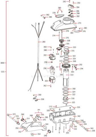
Propellers come in various configurations, including three-blade, four-blade, and even custom designs. Three-blade models are generally favored for their balance of speed and thrust, while four-blade options provide increased lift and stability, especially in rough conditions. Additionally, specialized designs like weedless propellers are available for specific applications, allowing for greater versatility on diverse waterways.
Factors Affecting Compatibility
When choosing a propeller, it is essential to consider the compatibility with the motor system. Key factors include the motor’s horsepower, the shaft size, and the intended use of the vessel. For instance, a higher pitch may be suitable for speed but could lead to reduced thrust at lower RPMs. Moreover, materials such as aluminum and stainless steel each have their own benefits and drawbacks, impacting durability and performance. Evaluating these aspects ensures that the selected propeller aligns well with the motor, resulting in improved efficiency and maneuverability.
Wiring Diagram of Minn Kota Ultrex 112 Motor
This section provides an overview of the electrical layout for a specific type of propulsion system, highlighting its various connections and components. Understanding this configuration is crucial for effective maintenance and troubleshooting, ensuring optimal performance of the motor.
Key Components
- Power Supply: The source providing energy to the motor.
- Control Unit: Manages the operational functions and settings.
- Propulsion Unit: The main mechanism that drives the craft forward.
- Wiring Harness: Connects all electrical components, allowing for communication and power transfer.
- Battery Connections: Links the power supply to the system, ensuring adequate energy flow.
Connection Overview
- Begin with the power supply, ensuring a stable connection.
- Link the control unit to the propulsion unit for effective command transmission.
- Connect the wiring harness, checking for any frays or damage.
- Secure all battery connections, confirming the polarity is correct.
- Test the system to ensure proper functionality of all components.
Understanding Electrical Layout and Connections
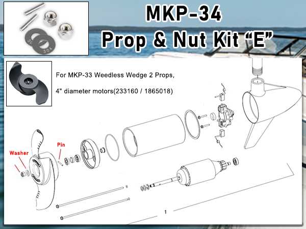
Grasping the principles of electrical configurations and linkages is crucial for optimizing performance and ensuring reliability in marine devices. A well-structured layout not only enhances functionality but also contributes to the safety and longevity of the equipment.
Components of an electrical system work in harmony to facilitate smooth operation. Each element, from power sources to control mechanisms, plays a significant role in achieving effective communication and energy transfer. Recognizing how these parts interact can lead to improved troubleshooting and maintenance practices.
Moreover, understanding the connection methods used can help users implement modifications or upgrades seamlessly. By familiarizing oneself with wiring techniques and the significance of proper grounding, individuals can enhance their overall experience and ensure optimal efficiency in their setups.
Steering System Breakdown and Its Maintenance
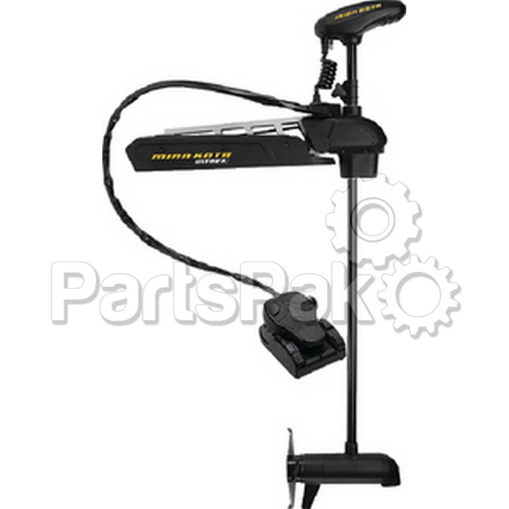
The steering mechanism of a watercraft plays a crucial role in ensuring precise navigation and control during operation. Understanding the components involved and their functions can aid in effective upkeep, leading to improved performance and longevity of the system. This section delves into the essential aspects of the steering assembly, highlighting key components and maintenance practices.
Key Components of the Steering Assembly
- Control Handle: The primary interface for steering, allowing the operator to maneuver the vessel.
- Linkage System: Connects the control handle to the motor, transmitting movement and direction changes.
- Gimbals: Provide a pivot point, enabling smooth rotational movement of the steering system.
- Mounting Bracket: Secures the assembly to the vessel, ensuring stability and alignment.
- Electrical Connections: Facilitate communication between the steering control and motor for precise adjustments.
Maintenance Tips for Optimal Performance
- Regular Inspection: Frequently check all components for signs of wear, corrosion, or damage.
- Lubrication: Apply appropriate lubricants to moving parts to reduce friction and prevent wear.
- Electrical Check: Ensure all electrical connections are secure and free from corrosion to maintain functionality.
- Adjustment: Periodically adjust the linkage system to ensure accurate steering response.
- Cleaning: Keep the steering assembly clean and free from debris, which can hinder performance.
